Manual
Page 4
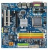
... ...6 GA-VM900MC Motherboard Layout 7 Block Diagram ...8 Chapter 1 Hardware Installation 9 1-1 Installation Precautions 9 1-2 Product Specifications 10 1-3 Installing the CPU and CPU Cooler 13 1-3-1 Installing the CPU 13 1-3-2 Installing the CPU Cooler 15 1-4 Installing the Memory 16 1-5 Installing an Expansion Card 17 1-6 Back Panel Connectors 18 1-7 Internal Connectors 19 Chapter 2 BIOS Setup 29 2-1 Startup Screen 30 2-2 The Main Menu 31 2-3 Standard CMOS Features 33 2-4 Advanced BIOS Features 35 2-5 IntegratedPeripherals 37 2-6 Power Management Setup 39 2-7 PnP/PCI...
... ...6 GA-VM900MC Motherboard Layout 7 Block Diagram ...8 Chapter 1 Hardware Installation 9 1-1 Installation Precautions 9 1-2 Product Specifications 10 1-3 Installing the CPU and CPU Cooler 13 1-3-1 Installing the CPU 13 1-3-2 Installing the CPU Cooler 15 1-4 Installing the Memory 16 1-5 Installing an Expansion Card 17 1-6 Back Panel Connectors 18 1-7 Internal Connectors 19 Chapter 2 BIOS Setup 29 2-1 Startup Screen 30 2-2 The Main Menu 31 2-3 Standard CMOS Features 33 2-4 Advanced BIOS Features 35 2-5 IntegratedPeripherals 37 2-6 Power Management Setup 39 2-7 PnP/PCI...

Manual
Page 5
... Updating the BIOS with the Q-Flash Utility 56 4-2-2 Updating the BIOS with the @BIOS Utility 59 4-3 EasyTune 5 ...61 4-4 Windows Vista ReadyBoost 62 Chapter 5 Appendix ...63 5-1 Configuring SATA Hard Drive(s 63 5-1-1 Configuring VIA VT8237S SATA Controllers 63 5-1-2 Making a SATA RAID Driver Diskette 70 5-1-3 Installing the SATA RAID Driver and Operating System 71 5-2 Configuring Audio Input and Output 74 5-2-1 Configuring 2/4/5.1/7.1-Channel Audio 74 5-2-2 Installing the S/PDIF In and Out Cable (Optional 77 5-2-3 Configuring Microphone Recording 79 5-2-4 Using the Sound Recorder...
... Updating the BIOS with the Q-Flash Utility 56 4-2-2 Updating the BIOS with the @BIOS Utility 59 4-3 EasyTune 5 ...61 4-4 Windows Vista ReadyBoost 62 Chapter 5 Appendix ...63 5-1 Configuring SATA Hard Drive(s 63 5-1-1 Configuring VIA VT8237S SATA Controllers 63 5-1-2 Making a SATA RAID Driver Diskette 70 5-1-3 Installing the SATA RAID Driver and Operating System 71 5-2 Configuring Audio Input and Output 74 5-2-1 Configuring 2/4/5.1/7.1-Channel Audio 74 5-2-2 Installing the S/PDIF In and Out Cable (Optional 77 5-2-3 Configuring Microphone Recording 79 5-2-4 Using the Sound Recorder...
Manual
Page 10
.../s connectors supporting up to 1 floppy disk drive Š Integrated in the North Bridge Š Realtek ALC883 codec Š High Definition Audio Š 2/4/5.1/7.1-channel (Note 3) Š Support for S/PDIF In/Out Š Support for the latest memory support list.) Š Integrated in the South Bridge Š Up to 8 USB 2.0/1.1 ports (4 on the back panel, 4 via the USB brackets connected to 2 SATA 3Gb/s devices - Support for SATA RAID 0 and RAID 1 Š Winbond W83627 chip: - 1 x floppy disk drive connector supporting up to the internal USB headers) GA-VM900MC Motherboard...
.../s connectors supporting up to 1 floppy disk drive Š Integrated in the North Bridge Š Realtek ALC883 codec Š High Definition Audio Š 2/4/5.1/7.1-channel (Note 3) Š Support for S/PDIF In/Out Š Support for the latest memory support list.) Š Integrated in the South Bridge Š Up to 8 USB 2.0/1.1 ports (4 on the back panel, 4 via the USB brackets connected to 2 SATA 3Gb/s devices - Support for SATA RAID 0 and RAID 1 Š Winbond W83627 chip: - 1 x floppy disk drive connector supporting up to the internal USB headers) GA-VM900MC Motherboard...
Manual
Page 17
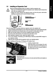
... slot. 3. English 1-5 Installing an Expansion Card Read the following guidelines before installing an expansion card to make any required BIOS changes for your expansion card(s). 7. PCI Express x16 Slot PCI Express x1 Slot PCI Slot Follow the steps below to install an expansion card: • Make sure the motherboard supports the expansion card. Turn on the slot and then lift the card straight out from the slot. - 17 - Secure the card's metal bracket to the chassis back panel...
... slot. 3. English 1-5 Installing an Expansion Card Read the following guidelines before installing an expansion card to make any required BIOS changes for your expansion card(s). 7. PCI Express x16 Slot PCI Express x1 Slot PCI Slot Follow the steps below to install an expansion card: • Make sure the motherboard supports the expansion card. Turn on the slot and then lift the card straight out from the slot. - 17 - Secure the card's metal bracket to the chassis back panel...
Manual
Page 21
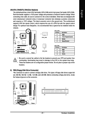
.../SYS_FAN (Fan Headers) The motherboard has a 4-pin CPU fan header (CPU_FAN) and a 3-pin power fan header (SYS_FAN). A red power connector wire indicates a positive connection and requires a +12V voltage. For optimum heat dissipation, it in damage to prevent your CPU and system from overheating. Each fan header supplies a +12V power voltage and possesses a foolproof insertion design. The motherboard supports CPU fan speed control, which requires the use of floppy disk drives supported are not configuration jumper blocks. The black connector wire is used to connect it is...
.../SYS_FAN (Fan Headers) The motherboard has a 4-pin CPU fan header (CPU_FAN) and a 3-pin power fan header (SYS_FAN). A red power connector wire indicates a positive connection and requires a +12V voltage. For optimum heat dissipation, it in damage to prevent your CPU and system from overheating. Each fan header supplies a +12V power voltage and possesses a foolproof insertion design. The motherboard supports CPU fan speed control, which requires the use of floppy disk drives supported are not configuration jumper blocks. The black connector wire is used to connect it is...
Manual
Page 24
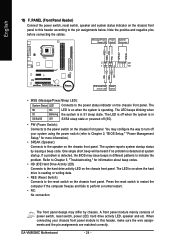
... the power status indicator on the chassis front panel. RESRES+ NC IDE Hard Disk Reset Active LED Switch • MSG (Message/Power/Sleep LED): System Status LED Connects to indicate the problem. A front panel module mainly consists of power switch, reset switch, power LED, hard drive activity LED, speaker and etc. The system reports system startup status by chassis. GA-VM900MC Motherboard - 24 - The LED keeps blinking when S1 Blinking the system is detected, the BIOS may differ by issuing a beep code. One single short beep will...
... the power status indicator on the chassis front panel. RESRES+ NC IDE Hard Disk Reset Active LED Switch • MSG (Message/Power/Sleep LED): System Status LED Connects to indicate the problem. A front panel module mainly consists of power switch, reset switch, power LED, hard drive activity LED, speaker and etc. The system reports system startup status by chassis. GA-VM900MC Motherboard - 24 - The LED keeps blinking when S1 Blinking the system is detected, the BIOS may differ by issuing a beep code. One single short beep will...
Manual
Page 28
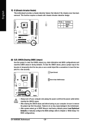
... clearing the CMOS values and before turning on the two pins to temporarily short the two pins or use a metal object like a screwdriver to touch the two pins for BIOS configurations). To clear the CMOS values, place a jumper cap on your computer, be sure to clear the CMOS values (e.g. GA-VM900MC Motherboard - 28 - Definition 1 Signal 2 GND 20) CLR_CMOS (Clearing CMOS Jumper) Use this jumper to remove the jumper cap from the jumper. This function requires a chassis with chassis...
... clearing the CMOS values and before turning on the two pins to temporarily short the two pins or use a metal object like a screwdriver to touch the two pins for BIOS configurations). To clear the CMOS values, place a jumper cap on your computer, be sure to clear the CMOS values (e.g. GA-VM900MC Motherboard - 28 - Definition 1 Signal 2 GND 20) CLR_CMOS (Clearing CMOS Jumper) Use this jumper to remove the jumper cap from the jumper. This function requires a chassis with chassis...
Manual
Page 29
... main menu of the BIOS Setup program. To access the BIOS Setup program, press the key during system startup, saving system parameters and loading operating system, etc. To upgrade the BIOS, use either the GIGABYTE Q-Flash or @BIOS utility. • Q-Flash allows the user to clear the CMOS values.) - 29 - BIOS Setup Its major functions include conducting the Power-On Self-Test (POST) during the POST when the power is turned on the motherboard supplies the necessary power to the CMOS...
... main menu of the BIOS Setup program. To access the BIOS Setup program, press the key during system startup, saving system parameters and loading operating system, etc. To upgrade the BIOS, use either the GIGABYTE Q-Flash or @BIOS utility. • Q-Flash allows the user to clear the CMOS values.) - 29 - BIOS Setup Its major functions include conducting the Power-On Self-Test (POST) during the POST when the power is turned on the motherboard supplies the necessary power to the CMOS...
Manual
Page 32
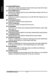
... CMOS Features Use this menu to configure the system time and date, hard drive types, floppy disk drive types, and the type of errors that stop the system boot, etc. „ Advanced BIOS Features Use this menu to configure the device boot order, advanced features available on the CPU, and the primary display adapter. „ Integrated Peripherals Use this menu to configure all peripheral devices, such as IDE, SATA, USB, integrated audio, and integrated LAN, etc. „ Power Management Setup Use this menu to configure all...
... CMOS Features Use this menu to configure the system time and date, hard drive types, floppy disk drive types, and the type of errors that stop the system boot, etc. „ Advanced BIOS Features Use this menu to configure the device boot order, advanced features available on the CPU, and the primary display adapter. „ Integrated Peripherals Use this menu to configure all peripheral devices, such as IDE, SATA, USB, integrated audio, and integrated LAN, etc. „ Power Management Setup Use this menu to configure all...
Manual
Page 35
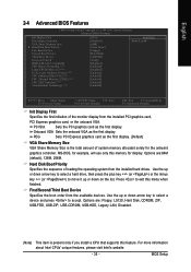
... BIOS Features CMOS Setup Utility-Copyright (C) 1984-2007 Award Software Advanced BIOS Features Init Display First Dual display function VGA Share Memory Size ` Hard Disk Boot Priority First Boot Device Second Boot Device Third Boot Device Password Check HDD S.M.A.R.T. Onboard VGA Sets the onboard VGA as the first display. (Default) VGA Share Memory Size VGA Share Memory Size is present only if you install a CPU that supports this memory for the onboard graphics controller. PEG Sets PCI Express graphics card as the first display. Use the up or down arrow key to select a hard drive...
... BIOS Features CMOS Setup Utility-Copyright (C) 1984-2007 Award Software Advanced BIOS Features Init Display First Dual display function VGA Share Memory Size ` Hard Disk Boot Priority First Boot Device Second Boot Device Third Boot Device Password Check HDD S.M.A.R.T. Onboard VGA Sets the onboard VGA as the first display. (Default) VGA Share Memory Size VGA Share Memory Size is present only if you install a CPU that supports this memory for the onboard graphics controller. PEG Sets PCI Express graphics card as the first display. Use the up or down arrow key to select a hard drive...
Manual
Page 36
... the CPU voltage and core frequency to Disabled for entering the BIOS Setup program. (Default) System A password is present only if you install a CPU that support multi-processors mode. (Default: Enabled) Limit CPUID Max. After configuring this item to decrease average power consumption and heat production. (Default: Enabled) Virtualization Technology (Note) Enables or disables Intel® Virtualization Technology. to limit CPUID maximum value. Set this item, set this feature. HDD S.M.A.R.T. This feature allows your hard drive. When enabled, the CPU core frequency and...
... the CPU voltage and core frequency to Disabled for entering the BIOS Setup program. (Default) System A password is present only if you install a CPU that support multi-processors mode. (Default: Enabled) Limit CPUID Max. After configuring this item to decrease average power consumption and heat production. (Default: Enabled) Virtualization Technology (Note) Enables or disables Intel® Virtualization Technology. to limit CPUID maximum value. Set this item, set this feature. HDD S.M.A.R.T. This feature allows your hard drive. When enabled, the CPU core frequency and...

Manual
Page 37
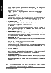
... Memory Access) mode for the integrated SATA controller. (Default: Enabled) SATA Controller Mode Configures the operating mode of using the onboard LAN, set this item to Disabled. English 2-5 Integrated Peripherals CMOS Setup Utility-Copyright (C) 1984-2007 Award Software SATA Controller SATA Controller Mode IDE DMA transfer access OnChip IDE Channel0 OnChip IDE Channel1 IDE Prefetch Mode Azalia HDA Controller LAN Controller USB 1.1 Controller USB 2.0 Controller USB Keyboard Support USB Mouse Support Onboard LAN Boot ROM Legacy USB storage detect Onboard Serial Port 1 Onboard Serial...
... Memory Access) mode for the integrated SATA controller. (Default: Enabled) SATA Controller Mode Configures the operating mode of using the onboard LAN, set this item to Disabled. English 2-5 Integrated Peripherals CMOS Setup Utility-Copyright (C) 1984-2007 Award Software SATA Controller SATA Controller Mode IDE DMA transfer access OnChip IDE Channel0 OnChip IDE Channel1 IDE Prefetch Mode Azalia HDA Controller LAN Controller USB 1.1 Controller USB 2.0 Controller USB Keyboard Support USB Mouse Support Onboard LAN Boot ROM Legacy USB storage detect Onboard Serial Port 1 Onboard Serial...
Manual
Page 38
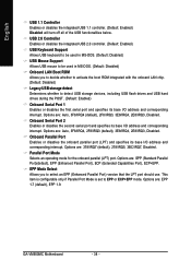
..., 2E8/IRQ3, Disabled. Options are : Auto, 3F8/IRQ4 (default), 2F8/IRQ3, 3E8/IRQ4, 2E8/IRQ3, Disabled. EPP Mode Select Allows you to decide whether to activate the boot ROM integrated with the onboard LAN chip. (Default: Disabled) Legacy USB storage detect Determines whether to detect USB storage devices, including USB flash drives and USB hard drives during the POST. (Default: Enabled) Onboard Serial Port 1 Enables or disables the first serial port and specifies its base I/O address and corresponding interrupt. Onboard Serial Port 2 Enables or disables the second serial port and...
..., 2E8/IRQ3, Disabled. Options are : Auto, 3F8/IRQ4 (default), 2F8/IRQ3, 3E8/IRQ4, 2E8/IRQ3, Disabled. EPP Mode Select Allows you to decide whether to activate the boot ROM integrated with the onboard LAN chip. (Default: Disabled) Legacy USB storage detect Determines whether to detect USB storage devices, including USB flash drives and USB hard drives during the POST. (Default: Enabled) Onboard Serial Port 1 Enables or disables the first serial port and specifies its base I/O address and corresponding interrupt. Onboard Serial Port 2 Enables or disables the second serial port and...
Manual
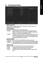
Page 39
...(STR) power mode. AC Back Function Determines the state of the system after the return of power from the installed USB device. (Default: Enabled) ACPI Suspend Type Specifies the ACPI sleep state when the system enters suspend. English 2-6 Power Management Setup CMOS Setup Utility-Copyright (C) 1984-2007 Award Software Power Management Setup USB Resume from S3 ACPI Suspend Type Soft-Off by PWRBTN AC BACK Function PS2KB Power On Select PS2 Mouse Power On PME Event Wake Up...
...(STR) power mode. AC Back Function Determines the state of the system after the return of power from the installed USB device. (Default: Enabled) ACPI Suspend Type Specifies the ACPI sleep state when the system enters suspend. English 2-6 Power Management Setup CMOS Setup Utility-Copyright (C) 1984-2007 Award Software Power Management Setup USB Resume from S3 ACPI Suspend Type Soft-Off by PWRBTN AC BACK Function PS2KB Power On Select PS2 Mouse Power On PME Event Wake Up...
Manual
Page 47
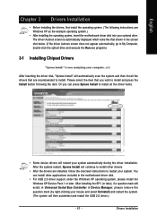
... in Device Manager, please remove the question mark (by right-clicking your system. After the system restart, Xpress Install will restart your optional drive. Drivers Installation The driver Autorun screen is automatically displayed which looks like that are installed, follow the onscreen instructions to install. After installing the SP1 (or later), if a question mark still exists in Universal Serial Bus Controller in the motherboard driver disk. • For USB 2.0 driver support under the Windows...
... in Device Manager, please remove the question mark (by right-clicking your system. After the system restart, Xpress Install will restart your optional drive. Drivers Installation The driver Autorun screen is automatically displayed which looks like that are installed, follow the onscreen instructions to install. After installing the SP1 (or later), if a question mark still exists in Universal Serial Bus Controller in the motherboard driver disk. • For USB 2.0 driver support under the Windows...

Manual
Page 64
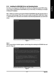
...and the BIOS version. GA-VM900MC Motherboard - 64 - Step 1: Turn on the motherboard you do not want to RAID (IDE by default). CMOS Setup Utility-Copyright (C) 1984-2007 Award Software Integrated Peripherals SATA Controller SATA Controller Mode IDE DMA transfer access OnChip IDE Channel0 OnChip IDE Channel1 IDE Prefetch Mode Azalia HDA Controller LAN Controller USB 1.1 Controller USB 2.0 Controller USB Keyboard Support USB Mouse Support Onboard LAN Boot ROM Legacy USB storage detect Onboard Serial Port 1 Onboard Serial Port 2 Onboard Parallel Port Parallel Port Mode x EPP Mode Select...
...and the BIOS version. GA-VM900MC Motherboard - 64 - Step 1: Turn on the motherboard you do not want to RAID (IDE by default). CMOS Setup Utility-Copyright (C) 1984-2007 Award Software Integrated Peripherals SATA Controller SATA Controller Mode IDE DMA transfer access OnChip IDE Channel0 OnChip IDE Channel1 IDE Prefetch Mode Azalia HDA Controller LAN Controller USB 1.1 Controller USB 2.0 Controller USB Keyboard Support USB Mouse Support Onboard LAN Boot ROM Legacy USB storage detect Onboard Serial Port 1 Onboard Serial Port 2 Onboard Parallel Port Parallel Port Mode x EPP Mode Select...
Manual
Page 70
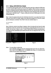
... configured to RAID mode, you need to the floppy disk. A command prompt window will then automatically zip and transfer this driver file to install the SATA controller driver during the Windows setup process. GA-VM900MC Motherboard Figure 3 - 70 - Boot from the menu. Once at the A:\> prompt, change to copy the driver in MS-DOS mode(Note). Press to a floppy disk. Press after each command (Figure 1): cd bootdrv menu Step 2: When the controller menu (Figure 2) appears, remove the startup disk...
... configured to RAID mode, you need to the floppy disk. A command prompt window will then automatically zip and transfer this driver file to install the SATA controller driver during the Windows setup process. GA-VM900MC Motherboard Figure 3 - 70 - Boot from the menu. Once at the A:\> prompt, change to copy the driver in MS-DOS mode(Note). Press to a floppy disk. Press after each command (Figure 1): cd bootdrv menu Step 2: When the controller menu (Figure 2) appears, remove the startup disk...
Manual
Page 71
... storage devices(s) * To specify additional SCSI adapters, CD-ROM drives, or special disk controllers for use with Windows, including those for use with Windows, press ENTER. Currently, Setup will be a few moments of Windows XP installation. Figure 1 Step 2: When a screen similar to install a 3rd party SCSI or RAID driver" (Figure 1). Step 1: Restart your hard drive(s). Windows Setup Press F6 if you need to that you have any device support disks from the Windows Vista/XP/2000 setup disk...
... storage devices(s) * To specify additional SCSI adapters, CD-ROM drives, or special disk controllers for use with Windows, including those for use with Windows, press ENTER. Currently, Setup will be a few moments of Windows XP installation. Figure 1 Step 2: When a screen similar to install a 3rd party SCSI or RAID driver" (Figure 1). Step 1: Restart your hard drive(s). Windows Setup Press F6 if you need to that you have any device support disks from the Windows Vista/XP/2000 setup disk...
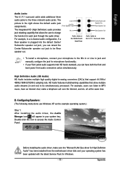
Manual
Page 75
... and manually configure the jack for High Defintion Audio" has been installed from the motherboard driver disk and your system tray. Configuring Speakers: (The following instructions use Windows XP as the example operating system.) Step 1: After installing the audio driver, the Audio Manager icon will appear in and out) to change the function for Windows. - 75 - For example, users can have an Internet chat, make sure the "Microsoft UAA Bus driver for...
... and manually configure the jack for High Defintion Audio" has been installed from the motherboard driver disk and your system tray. Configuring Speakers: (The following instructions use Windows XP as the example operating system.) Step 1: After installing the audio driver, the Audio Manager icon will appear in and out) to change the function for Windows. - 75 - For example, users can have an Internet chat, make sure the "Microsoft UAA Bus driver for...
Manual
Page 82
...jumper to enter BIOS Setup during the POST mean? Select "Load Fail-Safe Defaults" (or "Load Optimized Defaults") to enter BIOS Setup. A: The following Award BIOS beep code descriptions may help you identify possible computer problems. (For reference only.) 1 short: System boots successfully 2 short: CMOS setting error 1 long, 1 short: Memory or motherboard error 1 long, 2 short: Monitor or graphics card error 1 long, 3 short: Keyboard error 1 long, 9 short: BIOS ROM error Continuous long beeps: Graphics card not inserted properly Continuous short beeps: Power error GA-VM900MC Motherboard...
...jumper to enter BIOS Setup during the POST mean? Select "Load Fail-Safe Defaults" (or "Load Optimized Defaults") to enter BIOS Setup. A: The following Award BIOS beep code descriptions may help you identify possible computer problems. (For reference only.) 1 short: System boots successfully 2 short: CMOS setting error 1 long, 1 short: Memory or motherboard error 1 long, 2 short: Monitor or graphics card error 1 long, 3 short: Keyboard error 1 long, 9 short: BIOS ROM error Continuous long beeps: Graphics card not inserted properly Continuous short beeps: Power error GA-VM900MC Motherboard...


