Manual
Page 1
GA-VM900MC Intel® CoreTM 2 Duo / Intel® Pentium® D / Intel® Pentium® 4 / Celeron® D LGA775 Processor Motherboard User's Manual Rev. 1002 12ME-VM900MC-1002R * The WEEE marking on the product indicates this product must not be disposed of with user's other household waste and must be handed over to a designated collection point for the recycling of waste electrical and electronic equipment!! * The WEEE marking applies only in European Union's member states.
GA-VM900MC Intel® CoreTM 2 Duo / Intel® Pentium® D / Intel® Pentium® 4 / Celeron® D LGA775 Processor Motherboard User's Manual Rev. 1002 12ME-VM900MC-1002R * The WEEE marking on the product indicates this product must not be disposed of with user's other household waste and must be handed over to a designated collection point for the recycling of waste electrical and electronic equipment!! * The WEEE marking applies only in European Union's member states.
Manual
Page 2
Motherboard GA-VM900MC Jun. 26, 2007 Motherboard GA-VM900MC Jun. 27, 2007
Motherboard GA-VM900MC Jun. 26, 2007 Motherboard GA-VM900MC Jun. 27, 2007
Manual
Page 3
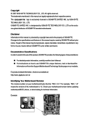
... be made by any means without prior notice. Example: Disclaimer Information in any form or by GIGABYTE without GIGABYTE's prior written permission. Check your motherboard looks like this product, GIGABYTE provides the following types of this : "REV: X.X." The trademarks mentioned in the use GIGABYTE's unique features, read or download the information on/from the Support...
... be made by any means without prior notice. Example: Disclaimer Information in any form or by GIGABYTE without GIGABYTE's prior written permission. Check your motherboard looks like this product, GIGABYTE provides the following types of this : "REV: X.X." The trademarks mentioned in the use GIGABYTE's unique features, read or download the information on/from the Support...
Manual
Page 4
Table of Contents Box Contents ...6 OptionalItems ...6 GA-VM900MC Motherboard Layout 7 Block Diagram ...8 Chapter 1 Hardware Installation 9 1-1 Installation Precautions 9 1-2 Product Specifications 10 1-3 Installing the CPU and CPU Cooler 13 1-3-1 Installing the CPU 13 1-3-2 Installing the CPU ...
Table of Contents Box Contents ...6 OptionalItems ...6 GA-VM900MC Motherboard Layout 7 Block Diagram ...8 Chapter 1 Hardware Installation 9 1-1 Installation Precautions 9 1-2 Product Specifications 10 1-3 Installing the CPU and CPU Cooler 13 1-3-1 Installing the CPU 13 1-3-2 Installing the CPU ...
Manual
Page 6
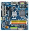
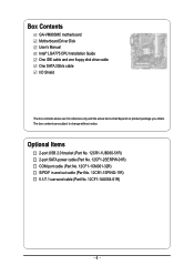
Box Contents GA-VM900MC motherboard Motherboard Driver Disk User's Manual Intel® LGA775 CPU Installation Guide One IDE cable and one floppy disk drive cable One SATA 3Gb/s cable I/O Shield The ...
Box Contents GA-VM900MC motherboard Motherboard Driver Disk User's Manual Intel® LGA775 CPU Installation Guide One IDE cable and one floppy disk drive cable One SATA 3Gb/s cable I/O Shield The ...

Manual
Page 9
... when handling electronic components such as a result of electrostatic discharge (ESD). English Chapter 1 Hardware Installation 1-1 Installation Precautions The motherboard contains numerous delicate electronic circuits and components which can lead to damage to system components as well as physical harm to the ...come in a high-temperature environment. • Turning on the computer power during the installation process can become damaged as a motherboard, CPU or memory. Hardware Installation These stickers are required for warranty validation. • Always remove the AC power by ...
... when handling electronic components such as a result of electrostatic discharge (ESD). English Chapter 1 Hardware Installation 1-1 Installation Precautions The motherboard contains numerous delicate electronic circuits and components which can lead to damage to system components as well as physical harm to the ...come in a high-temperature environment. • Turning on the computer power during the installation process can become damaged as a motherboard, CPU or memory. Hardware Installation These stickers are required for warranty validation. • Always remove the AC power by ...
Manual
Page 10
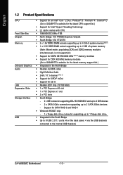
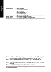
...; Support for an Intel® CoreTM 2 Duo / Pentium® D / Pentium® 4 / Celeron® D (Go to GIGABYTE's website for the latest CPU support list.) Š Support for the latest memory support list.) Š Integrated in the South Bridge &#...for DDR2 667/533/400 MHz (Note 2) memory modules Š Support for DDR 400 MHz memory modules (Go to GIGABYTE's website for Intel® Hyper-Threading Technology Š L2 cache varies with CPU Š 1066/800/533 MHz FSB... memory(Note 1) Š 1 x 2.5V DDR DIMM socket supporting up to the internal USB headers) GA-VM900MC Motherboard - 10 -
...; Support for an Intel® CoreTM 2 Duo / Pentium® D / Pentium® 4 / Celeron® D (Go to GIGABYTE's website for the latest CPU support list.) Š Support for the latest memory support list.) Š Integrated in the South Bridge &#...for DDR2 667/533/400 MHz (Note 2) memory modules Š Support for DDR 400 MHz memory modules (Go to GIGABYTE's website for Intel® Hyper-Threading Technology Š L2 cache varies with CPU Š 1066/800/533 MHz FSB... memory(Note 1) Š 1 x 2.5V DDR DIMM socket supporting up to the internal USB headers) GA-VM900MC Motherboard - 10 -
Manual
Page 12
GA-VM900MC Motherboard - 12 - English Unique Features Bundled Software Operating System Form Factor Š Support for @BIOS Š Support for Download Center Š Support for Q-Flash Š Support ... memory. (Note 3) A 5.1/7.1 surround cable (optional) needs to be installed if you wish to enable 7.1-channel audio output. (Note 4) Available functions in Easytune may differ by motherboard model.
GA-VM900MC Motherboard - 12 - English Unique Features Bundled Software Operating System Form Factor Š Support for @BIOS Š Support for Download Center Š Support for Q-Flash Š Support ... memory. (Note 3) A 5.1/7.1 surround cable (optional) needs to be installed if you wish to enable 7.1-channel audio output. (Note 4) Available functions in Easytune may differ by motherboard model.
Manual
Page 13
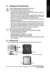
mended that the motherboard supports the CPU. (Go to GIGABYTE's website for the latest CPU support list.) • Always turn off the computer and unplug the power cord from the power outlet before you begin ... Features," for instructions on the computer if the CPU cooler is optimized for the peripherals. It is not recom- Locate the alignment keys on the motherboard CPU socket and the notches on the CPU Hardware Installation Notch Triangle Pin One Marking on the CPU. English 1-3 Installing the CPU and CPU Cooler...
mended that the motherboard supports the CPU. (Go to GIGABYTE's website for the latest CPU support list.) • Always turn off the computer and unplug the power cord from the power outlet before you begin ... Features," for instructions on the computer if the CPU cooler is optimized for the peripherals. It is not recom- Locate the alignment keys on the motherboard CPU socket and the notches on the CPU Hardware Installation Notch Triangle Pin One Marking on the CPU. English 1-3 Installing the CPU and CPU Cooler...
Manual
Page 14
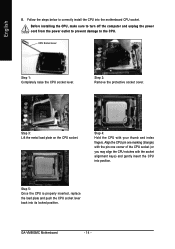
... sure to turn off the computer and unplug the power cord from the power outlet to prevent damage to correctly install the CPU into the motherboard CPU socket. CPU Socket Lever Step 1: Completely raise the CPU socket lever. English B. Step 4: Hold the CPU with the socket alignment keys) and gently insert... your thumb and index fingers. Step 5: Once the CPU is properly inserted, replace the load plate and push the CPU socket lever back into position. GA-VM900MC Motherboard - 14 -
... sure to turn off the computer and unplug the power cord from the power outlet to prevent damage to correctly install the CPU into the motherboard CPU socket. CPU Socket Lever Step 1: Completely raise the CPU socket lever. English B. Step 4: Hold the CPU with the socket alignment keys) and gently insert... your thumb and index fingers. Step 5: Once the CPU is properly inserted, replace the load plate and push the CPU socket lever back into position. GA-VM900MC Motherboard - 14 -
Manual
Page 15
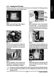
...an even and thin layer of thermal grease on the surface of the installed CPU. Step 4: You should hear a "click" when pushing down on the motherboard. Step 6: Finally, attach the power connector of the CPU cooler to the CPU fan header (CPU_FAN) on the push pins diagonally. Use extreme care when..., is complete. Check that the Male and Female push pins are joined closely. (Refer to your CPU cooler installation manual for instructions on the motherboard. Hardware Installation English 1-3-2 Installing the CPU Cooler Follow the steps below to correctly install the CPU cooler on the...
...an even and thin layer of thermal grease on the surface of the installed CPU. Step 4: You should hear a "click" when pushing down on the motherboard. Step 6: Finally, attach the power connector of the CPU cooler to the CPU fan header (CPU_FAN) on the push pins diagonally. Use extreme care when..., is complete. Check that the Male and Female push pins are joined closely. (Refer to your CPU cooler installation manual for instructions on the motherboard. Hardware Installation English 1-3-2 Installing the CPU Cooler Follow the steps below to correctly install the CPU cooler on the...
Manual
Page 16
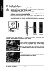
... ends of the memory, push down on the socket. Place the memory module on the memory and insert it can be used. (Go to GIGABYTE's website for the latest memory support list.) • Always turn off the computer and unplug the power cord from the power outlet before you... your fingers on the top edge of the memory socket. As indicated in the picture on the left, place your memory modules in one direction. GA-VM900MC Motherboard - 16 - Step 2: The clips at both ends of the memory module. A memory module can only fit in the memory sockets. English DDRII1 DDRII2 DDR1 ...
... ends of the memory, push down on the socket. Place the memory module on the memory and insert it can be used. (Go to GIGABYTE's website for the latest memory support list.) • Always turn off the computer and unplug the power cord from the power outlet before you... your fingers on the top edge of the memory socket. As indicated in the picture on the left, place your memory modules in one direction. GA-VM900MC Motherboard - 16 - Step 2: The clips at both ends of the memory module. A memory module can only fit in the memory sockets. English DDRII1 DDRII2 DDR1 ...
Manual
Page 17
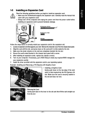
... turn off the computer and unplug the power cord from the power outlet before you begin to install an expansion card: • Make sure the motherboard supports the expansion card. Turn on the card are completely inserted into the PCI Express x16 slot. Example: Installing and Removing a PCI Express x16 Graphics...
... turn off the computer and unplug the power cord from the power outlet before you begin to install an expansion card: • Make sure the motherboard supports the expansion card. Turn on the card are completely inserted into the PCI Express x16 slot. Example: Installing and Removing a PCI Express x16 Graphics...

Manual
Page 18
...LED: State Description Blinking Data transmission or receiving is occurring Off No data transmission or receiving is also called a printer port. Use this port. GA-VM900MC Motherboard - 18 - Connect a monitor that supports D-Sub connection to prevent an electrical short inside the cable connector. This jack can be used to... a back panel connector, first remove the cable from your device and then remove it from the motherboard. • When removing the cable, pull it side to side to this audio jack for line in devices such as an USB ...
...LED: State Description Blinking Data transmission or receiving is occurring Off No data transmission or receiving is also called a printer port. Use this port. GA-VM900MC Motherboard - 18 - Connect a monitor that supports D-Sub connection to prevent an electrical short inside the cable connector. This jack can be used to... a back panel connector, first remove the cable from your device and then remove it from the motherboard. • When removing the cable, pull it side to side to this audio jack for line in devices such as an USB ...

Manual
Page 19
Microphones must be sure to turn off the devices and your devices are compliant with the connectors you need to the instructions on the motherboard. - 19 - Hardware Installation English Mic In Jack (Pink) The default Mic in Chapter 5, "Configuring 2/4/5.1/7.1Channel Audio." 1-7 Internal Connectors 1 3 2 11 6 4 7 12 18 9 13 14 15 5 16 ...
Microphones must be sure to turn off the devices and your devices are compliant with the connectors you need to the instructions on the motherboard. - 19 - Hardware Installation English Mic In Jack (Pink) The default Mic in Chapter 5, "Configuring 2/4/5.1/7.1Channel Audio." 1-7 Internal Connectors 1 3 2 11 6 4 7 12 18 9 13 14 15 5 16 ...
Manual
Page 20
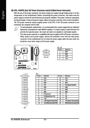
... power connector possesses a foolproof design. Before connecting the power connector, first make sure the power supply is turned off and all the components on the motherboard. When using a 2x10 power supply. 3 4 1 2 ATX_12V ATX_12V : Pin No. 1 2 3 4 Definition GND GND +12V +12V 12 24 1 13 ATX ATX : Pin No. 1 2 3 4 5... PS_ON(soft On/Off) GND GND GND -5V +5V +5V +5V (Only for 2x12-pinATX) GND (Only for 2x12-pin ATX) GA-VM900MC Motherboard - 20 - Do not insert the power supply cable into pins under the protective cover when using a 2x12 power supply, remove the protective...
... power connector possesses a foolproof design. Before connecting the power connector, first make sure the power supply is turned off and all the components on the motherboard. When using a 2x10 power supply. 3 4 1 2 ATX_12V ATX_12V : Pin No. 1 2 3 4 Definition GND GND +12V +12V 12 24 1 13 ATX ATX : Pin No. 1 2 3 4 5... PS_ON(soft On/Off) GND GND GND -5V +5V +5V +5V (Only for 2x12-pinATX) GND (Only for 2x12-pin ATX) GA-VM900MC Motherboard - 20 - Do not insert the power supply cable into pins under the protective cover when using a 2x12 power supply, remove the protective...
Manual
Page 21
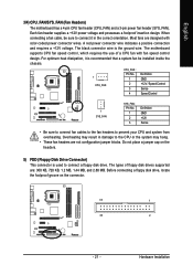
...connection and requires a +12V voltage. Most fans are : 360 KB, 720 KB, 1.2 MB, 1.44 MB, and 2.88 MB. The motherboard supports CPU fan speed control, which requires the use of floppy disk drives supported are designed with fan speed control design. Overheating may hang. •...; These fan headers are not configuration jumper blocks. English 3/4) CPU_FAN/SYS_FAN (Fan Headers) The motherboard has a 4-pin CPU fan header (CPU_FAN) and a 3-pin power fan header (SYS_FAN). Before connecting a floppy disk drive, locate the foolproof ...
...connection and requires a +12V voltage. Most fans are : 360 KB, 720 KB, 1.2 MB, 1.44 MB, and 2.88 MB. The motherboard supports CPU fan speed control, which requires the use of floppy disk drives supported are designed with fan speed control design. Overheating may hang. •...; These fan headers are not configuration jumper blocks. English 3/4) CPU_FAN/SYS_FAN (Fan Headers) The motherboard has a 4-pin CPU fan header (CPU_FAN) and a 3-pin power fan header (SYS_FAN). Before connecting a floppy disk drive, locate the foolproof ...

Manual
Page 22
... 1 IDE2 7) SATAII0 / SATAII1 (SATA 3Gb/s Connectors, Controlled by VIA VT8237S) The SATA connectors conform to two IDE devices such as hard drives and optical drives. GA-VM900MC Motherboard - 22 - If you wish to connect two IDE devices, remember to set the jumpers and the cabling according to the role of the IDE devices...
... 1 IDE2 7) SATAII0 / SATAII1 (SATA 3Gb/s Connectors, Controlled by VIA VT8237S) The SATA connectors conform to two IDE devices such as hard drives and optical drives. GA-VM900MC Motherboard - 22 - If you wish to connect two IDE devices, remember to set the jumpers and the cabling according to the role of the IDE devices...
Manual
Page 24
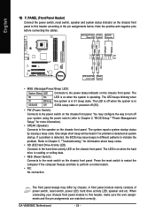
... in S3/S4/S5 Off S3/S4 sleep state or powered off when the system is detected, the BIOS may differ by issuing a beep code. GA-VM900MC Motherboard - 24 - PW+ PWSPEAK+ SPEAK- 2 20 1 19 HD+ HD- If a problem is in S1 sleep state. Refer to Chapter 5, "Troubleshooting," for more information). • SPEAK (Speaker...
... in S3/S4/S5 Off S3/S4 sleep state or powered off when the system is detected, the BIOS may differ by issuing a beep code. GA-VM900MC Motherboard - 24 - PW+ PWSPEAK+ SPEAK- 2 20 1 19 HD+ HD- If a problem is in S1 sleep state. Refer to Chapter 5, "Troubleshooting," for more information). • SPEAK (Speaker...
Manual
Page 25
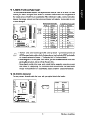
... the wire assignments of the module connector match the pin assignments of a single plug. Incorrect connection between the module connector and the motherboard header will make the device unable to this header. If your chassis provides an AC'97 front panel audio module, refer to the...) You may connect your optical drive to the header. You may connect the audio cable that has separated connectors on each wire instead of the motherboard header. For HD Front Panel Audio: Pin No. Definition For AC'97 Front Panel Audio: Pin No. Definition 1 10 9 2 MIC2_L GND 1 MIC 2 GND 3 2...
... the wire assignments of the module connector match the pin assignments of a single plug. Incorrect connection between the module connector and the motherboard header will make the device unable to this header. If your chassis provides an AC'97 front panel audio module, refer to the...) You may connect your optical drive to the header. You may connect the audio cable that has separated connectors on each wire instead of the motherboard header. For HD Front Panel Audio: Pin No. Definition For AC'97 Front Panel Audio: Pin No. Definition 1 10 9 2 MIC2_L GND 1 MIC 2 GND 3 2...


