
Manual
Page 1
..."Installing the SATA RAID/AHCI Driver and Operating System." ) Step 3: Install the motherboard drivers and the X.H.D utiltiy After installing the operating system, insert the motherboard driver disk. eXtreme Hard Drive (X.H.D) With GIGABYTE eXtreme Hard Drive (X.H.D)(Note 1), users can quickly configure a RAIDready system for complex...A. Setting Up a RAID-Ready System Step 1: Configure the system BIOS Enter the system BIOS Setup program, set up all motherboard drivers, including the X.H.D utility. You can click the Xpress Install All button to automatically install all of your data to ...
..."Installing the SATA RAID/AHCI Driver and Operating System." ) Step 3: Install the motherboard drivers and the X.H.D utiltiy After installing the operating system, insert the motherboard driver disk. eXtreme Hard Drive (X.H.D) With GIGABYTE eXtreme Hard Drive (X.H.D)(Note 1), users can quickly configure a RAIDready system for complex...A. Setting Up a RAID-Ready System Step 1: Configure the system BIOS Enter the system BIOS Setup program, set up all motherboard drivers, including the X.H.D utility. You can click the Xpress Install All button to automatically install all of your data to ...
Manual
Page 1
GA-P55A-UD4P GA-P55A-UD4 LGA1156 socket motherboard for Intel® Core™ i7 processor family/ Intel® Core™ i5 processor family User's Manual Rev. 1002 12ME-P55AU4P-1002R
GA-P55A-UD4P GA-P55A-UD4 LGA1156 socket motherboard for Intel® Core™ i7 processor family/ Intel® Core™ i5 processor family User's Manual Rev. 1002 12ME-P55AU4P-1002R
Manual
Page 2
Motherboard GA-P55A-UD4P/GA-P55A-UD4 Oct. 16, 2009 Motherboard GA-P55A-UD4P / GA-P55A-UD4 Oct. 16, 2009
Motherboard GA-P55A-UD4P/GA-P55A-UD4 Oct. 16, 2009 Motherboard GA-P55A-UD4P / GA-P55A-UD4 Oct. 16, 2009
Manual
Page 3
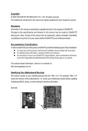
... part of this manual may be reproduced, copied, translated, transmitted, or published in the use GIGABYTE's unique features, read or download the information on/from the Support&Downloads\Motherboard\Technology Guide page on your motherboard revision before updating motherboard BIOS, drivers, or when looking for technical information. For detailed product information, carefully read the...
... part of this manual may be reproduced, copied, translated, transmitted, or published in the use GIGABYTE's unique features, read or download the information on/from the Support&Downloads\Motherboard\Technology Guide page on your motherboard revision before updating motherboard BIOS, drivers, or when looking for technical information. For detailed product information, carefully read the...
Manual
Page 4
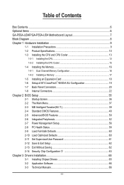
Table of Contents Box Contents...6 Optional Items...6 GA-P55A-UD4P/GA-P55A-UD4 Motherboard Layout 7 Block Diagram...8 Chapter 1 Hardware Installation 9 1-1 Installation Precautions 9 1-2 Product Specifications 10 1-3 Installing the CPU and CPU Cooler 13 1-3-1 Installing the CPU 13 1-3-2 Installing the CPU ...
Table of Contents Box Contents...6 Optional Items...6 GA-P55A-UD4P/GA-P55A-UD4 Motherboard Layout 7 Block Diagram...8 Chapter 1 Hardware Installation 9 1-1 Installation Precautions 9 1-2 Product Specifications 10 1-3 Installing the CPU and CPU Cooler 13 1-3-1 Installing the CPU 13 1-3-2 Installing the CPU ...
Manual
Page 6
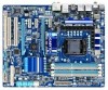
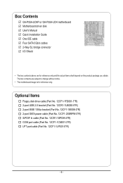
Box Contents GA-P55A-UD4P or GA-P55A-UD4 motherboard Motherboard driver disk User's Manual Quick Installation Guide One IDE cable Four SATA 3Gb/s cables 2-Way SLI bridge connector I/O Shield • The box contents above are subject to change without notice. • The motherboard image is for reference only and the actual items shall depend on the product package...
Box Contents GA-P55A-UD4P or GA-P55A-UD4 motherboard Motherboard driver disk User's Manual Quick Installation Guide One IDE cable Four SATA 3Gb/s cables 2-Way SLI bridge connector I/O Shield • The box contents above are subject to change without notice. • The motherboard image is for reference only and the actual items shall depend on the product package...
Manual
Page 7
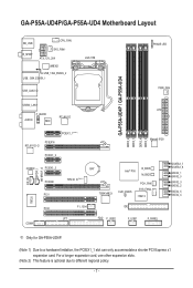
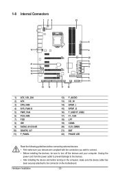
...hardware limitation, the PCIEX1_1 slot can only accommodate a shorter PCI Express x1 expansion card. GA-P55A-UD4P/GA-P55A-UD4 Motherboard Layout KB_USB R_SPDIF CPU_FAN SYS_FAN1 ATX_12V_2X4 JMB362 USB_1394_ESATA_2 USB_1394_ESATA_1 USB_LAN2 j LGA1156 PHASE LED PWR_FAN GA-P55A-UD4P / GA-P55A-UD4 DDR3_2 DDR3_1 DDR3_4 DDR3_3 USB30_LAN1 ATX F_AUDIO AUDIO NEC RTL8111D PCIEX1_1(Note 1) PCIEX16 RTL8111D ...SATA2_0 SATA2_3 SATA2_2 SATA2_5 SATA2_4 IT8720 PCI2 COMA F1_1394 LPT IDE FDD F_USB2 F_USB1 F_PANEL j Only for GA-P55A-UD4P. (Note 1) Due to different regional policy. - 7 -
...hardware limitation, the PCIEX1_1 slot can only accommodate a shorter PCI Express x1 expansion card. GA-P55A-UD4P/GA-P55A-UD4 Motherboard Layout KB_USB R_SPDIF CPU_FAN SYS_FAN1 ATX_12V_2X4 JMB362 USB_1394_ESATA_2 USB_1394_ESATA_1 USB_LAN2 j LGA1156 PHASE LED PWR_FAN GA-P55A-UD4P / GA-P55A-UD4 DDR3_2 DDR3_1 DDR3_4 DDR3_3 USB30_LAN1 ATX F_AUDIO AUDIO NEC RTL8111D PCIEX1_1(Note 1) PCIEX16 RTL8111D ...SATA2_0 SATA2_3 SATA2_2 SATA2_5 SATA2_4 IT8720 PCI2 COMA F1_1394 LPT IDE FDD F_USB2 F_USB1 F_PANEL j Only for GA-P55A-UD4P. (Note 1) Due to different regional policy. - 7 -
Manual
Page 9
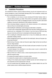
... an electrostatic discharge (ESD) wrist strap when handling electronic com- These stickers are connected tightly and securely. • When handling the motherboard, avoid touching any installation steps or have it on top of an antistatic pad or within the computer casing. • Do not ... using the product, please verify that all cables and power connectors of your hardware components are connected. • To prevent damage to the motherboard, do not have an ESD wrist strap, keep your dealer. Prior to installation, carefully read the user's manual and follow these procedures: ...
... an electrostatic discharge (ESD) wrist strap when handling electronic com- These stickers are connected tightly and securely. • When handling the motherboard, avoid touching any installation steps or have it on top of an antistatic pad or within the computer casing. • Do not ... using the product, please verify that all cables and power connectors of your hardware components are connected. • To prevent damage to the motherboard, do not have an ESD wrist strap, keep your dealer. Prior to installation, carefully read the user's manual and follow these procedures: ...
Manual
Page 12
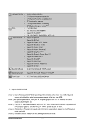
... Internet Security (OEM version) Operating System w Support for Microsoft® Windows® 7/Vista/XP Form Factor w ATX Form Factor; 30.5cm x 24.4cm j Only for GA-P55A-UD4P. (Note 1) Due to Windows Vista/XP 32-bit operating system limitation, when more than 4 GB of physical memory is installed, the actual memory size...
... Internet Security (OEM version) Operating System w Support for Microsoft® Windows® 7/Vista/XP Form Factor w ATX Form Factor; 30.5cm x 24.4cm j Only for GA-P55A-UD4P. (Note 1) Due to Windows Vista/XP 32-bit operating system limitation, when more than 4 GB of physical memory is installed, the actual memory size...
Manual
Page 13
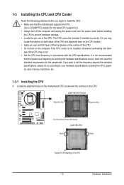
... one of the CPU Socket LGA1156 CPU Notch Notch Triangle Pin One Marking on the computer if the CPU cooler is not recommended that the motherboard supports the CPU. (Go to GIGABYTE's website for the peripherals. Locate the alignment keys on the...
... one of the CPU Socket LGA1156 CPU Notch Notch Triangle Pin One Marking on the computer if the CPU cooler is not recommended that the motherboard supports the CPU. (Go to GIGABYTE's website for the peripherals. Locate the alignment keys on the...
Manual
Page 14
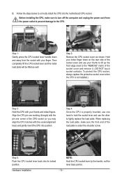
... cord from the socket with the socket alignment keys) and gently insert the CPU into position. Step 5: Push the CPU socket lever back into the motherboard CPU socket. Step 1: Gently press the CPU socket lever handle down on the rear side of the socket cover and remove it. (DO NOT touch...
... cord from the socket with the socket alignment keys) and gently insert the CPU into position. Step 5: Push the CPU socket lever back into the motherboard CPU socket. Step 1: Gently press the CPU socket lever handle down on the rear side of the socket cover and remove it. (DO NOT touch...
Manual
Page 15
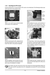
...thermal grease/tape between the CPU cooler and CPU may damage the CPU. - 15 - Step 6: Finally, attach the power connector of the motherboard. Check that the Male and Female push pins are joined closely. (Refer to your CPU cooler installation manual for instructions on installing the cooler.)...the cooler atop the CPU, aligning the four push pins through the pin holes on the motherboard. 1-3-2 Installing the CPU Cooler Follow the steps below to correctly install the CPU cooler on the motherboard. (The following procedure uses Intel® boxed cooler as the picture above shows, the ...
...thermal grease/tape between the CPU cooler and CPU may damage the CPU. - 15 - Step 6: Finally, attach the power connector of the motherboard. Check that the Male and Female push pins are joined closely. (Refer to your CPU cooler installation manual for instructions on installing the cooler.)...the cooler atop the CPU, aligning the four push pins through the pin holes on the motherboard. 1-3-2 Installing the CPU Cooler Follow the steps below to correctly install the CPU cooler on the motherboard. (The following procedure uses Intel® boxed cooler as the picture above shows, the ...
Manual
Page 16
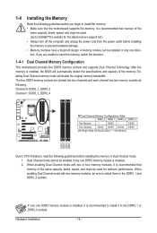
... cord from the power outlet before installing the memory to insert the memory, switch the direction. 1-4-1 Dual Channel Memory Configuration This motherboard provides four DDR3 memory sockets and supports Dual Channel Technology. If you begin to install it in the DDR3_1 or DDR3_3 sockets....memory module is installed, it is installed, the BIOS will double the original memory bandwidth. A memory module can be used . (Go to GIGABYTE's website for optimum performance. After the memory is recommended to install the memory: • Make sure that memory of the same capacity, ...
... cord from the power outlet before installing the memory to insert the memory, switch the direction. 1-4-1 Dual Channel Memory Configuration This motherboard provides four DDR3 memory sockets and supports Dual Channel Technology. If you begin to install it in the DDR3_1 or DDR3_3 sockets....memory module is installed, it is installed, the BIOS will double the original memory bandwidth. A memory module can be used . (Go to GIGABYTE's website for optimum performance. After the memory is recommended to install the memory: • Make sure that memory of the same capacity, ...
Manual
Page 17
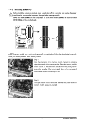
... left, place your memory modules in one direction. Spread the retaining clips at both ends of the memory module. Place the memory module on this motherboard. 1-4-2 Installing a Memory Before installing a memory module, make sure to turn off the computer and unplug the power cord from the power outlet to prevent damage...
... left, place your memory modules in one direction. Spread the retaining clips at both ends of the memory module. Place the memory module on this motherboard. 1-4-2 Installing a Memory Before installing a memory module, make sure to turn off the computer and unplug the power cord from the power outlet to prevent damage...
Manual
Page 18
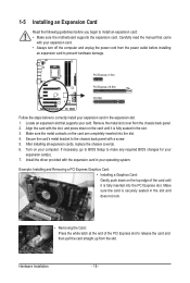
... install your computer. 1-5 Installing an Expansion Card Read the following guidelines before installing an expansion card to install an expansion card: • Make sure the motherboard supports the expansion card. Install the driver provided with the slot, and press down on the card until it is fully inserted into the slot...
... install your computer. 1-5 Installing an Expansion Card Read the following guidelines before installing an expansion card to install an expansion card: • Make sure the motherboard supports the expansion card. Install the driver provided with the slot, and press down on the card until it is fully inserted into the slot...
Manual
Page 19
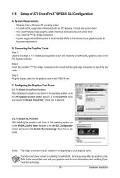
... the graphics card driver in the CrossFireX/SLI gold edge connectors on the PCIEX16 slot. Browse to the ATI Catalyst Control Center. A CrossFireX/SLI-supported motherboard with two PCI Express x16 slots and correct driver - To Enable SLI Function After installing the graphics card driver in "1-5 Installing an Expansion Card" and...
... the graphics card driver in the CrossFireX/SLI gold edge connectors on the PCIEX16 slot. Browse to the ATI Catalyst Control Center. A CrossFireX/SLI-supported motherboard with two PCI Express x16 slots and correct driver - To Enable SLI Function After installing the graphics card driver in "1-5 Installing an Expansion Card" and...
Manual
Page 20
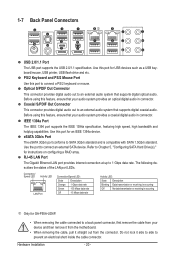
.... Coaxial S/PDIF Out Connector This connector provides digital audio out to an external audio system that your device and then remove it from the motherboard. • When removing the cable, pull it side to side to a back panel connector, first remove the cable from the connector. ... USB flash drive and etc. Before using this port to 1 Gbps data rate. Use the port to Chapter 5, "Configuring SATA Hard Drive(s)," for GA-P55A-UD4P. • When removing the cable connected to prevent an electrical short inside the cable connector. eSATA 3Gb/s Port The eSATA 3Gb/s port conforms...
.... Coaxial S/PDIF Out Connector This connector provides digital audio out to an external audio system that your device and then remove it from the motherboard. • When removing the cable, pull it side to side to a back panel connector, first remove the cable from the connector. ... USB flash drive and etc. Before using this port to 1 Gbps data rate. Use the port to Chapter 5, "Configuring SATA Hard Drive(s)," for GA-P55A-UD4P. • When removing the cable connected to prevent an electrical short inside the cable connector. eSATA 3Gb/s Port The eSATA 3Gb/s port conforms...
Manual
Page 22
... devices and your devices are compliant with the connectors you wish to connect. • Before installing the devices, be sure to the connector on the motherboard.
... devices and your devices are compliant with the connectors you wish to connect. • Before installing the devices, be sure to the connector on the motherboard.
Manual
Page 23
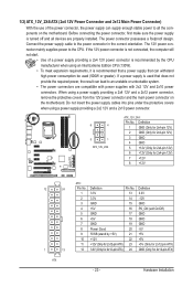
...power supply providing a 2x4 12V and a 2x12 power connector, remove the protective covers from the 12V power connector and the main power connector on the motherboard. When using a power supply providing a 2x2 12V and a 2x10 power connector. 8 4 5 1 ATX_12V_2X4 ATX_12V_2X4: Pin No. The 12V power ...are properly installed. Before connecting the power connector, first make sure the power supply is turned off and all the components on the motherboard. 1/2) ATX_12V_2X4/ATX (2x4 12V Power Connector and 2x12 Main Power Connector) With the use of a power supply providing a 2x4 ...
...power supply providing a 2x4 12V and a 2x12 power connector, remove the protective covers from the 12V power connector and the main power connector on the motherboard. When using a power supply providing a 2x2 12V and a 2x10 power connector. 8 4 5 1 ATX_12V_2X4 ATX_12V_2X4: Pin No. The 12V power ...are properly installed. Before connecting the power connector, first make sure the power supply is turned off and all the components on the motherboard. 1/2) ATX_12V_2X4/ATX (2x4 12V Power Connector and 2x12 Main Power Connector) With the use of a power supply providing a 2x4 ...
Manual
Page 24
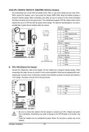
.... Most fans are not configuration jumper blocks. Do not place a jumper cap on the headers. 3/4/5) CPU_FAN/SYS_FAN1/SYS_FAN2/PWR_FAN (Fan Headers) The motherboard has a 4-pin CPU fan header (CPU_FAN), a 4-pin (SYS_FAN2) and two 3-pin (SYS_ FAN1) system fan headers, and a 3-pin ...power fan header (PWR_FAN). Most fan headers possess a foolproof insertion design. The motherboard supports CPU fan speed control, which requires the use of a CPU fan with colorcoded power connector wires. Definition 1 CPU_FAN 1 GND 2 +12V / Speed ...
.... Most fans are not configuration jumper blocks. Do not place a jumper cap on the headers. 3/4/5) CPU_FAN/SYS_FAN1/SYS_FAN2/PWR_FAN (Fan Headers) The motherboard has a 4-pin CPU fan header (CPU_FAN), a 4-pin (SYS_FAN2) and two 3-pin (SYS_ FAN1) system fan headers, and a 3-pin ...power fan header (PWR_FAN). Most fan headers possess a foolproof insertion design. The motherboard supports CPU fan speed control, which requires the use of a CPU fan with colorcoded power connector wires. Definition 1 CPU_FAN 1 GND 2 +12V / Speed ...


