
Manual
Page 1
... following procedure details the steps to load the SATA controller driver first. Or you have to set up a RAID 0 array. 2. eXtreme Hard Drive (X.H.D) With GIGABYTE eXtreme Hard Drive (X.H.D)(Note 1), users can quickly configure a RAIDready system for RAID 0. Before installing the operating system, you can go to the Application Software screen to Chapter 5, "Installing the SATA RAID/AHCI Driver and Operating System." ) Step 3: Install the motherboard drivers and the X.H.D utiltiy After installing the operating system, insert the motherboard driver disk.
... following procedure details the steps to load the SATA controller driver first. Or you have to set up a RAID 0 array. 2. eXtreme Hard Drive (X.H.D) With GIGABYTE eXtreme Hard Drive (X.H.D)(Note 1), users can quickly configure a RAIDready system for RAID 0. Before installing the operating system, you can go to the Application Software screen to Chapter 5, "Installing the SATA RAID/AHCI Driver and Operating System." ) Step 3: Install the motherboard drivers and the X.H.D utiltiy After installing the operating system, insert the motherboard driver disk.
Manual
Page 3
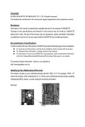
.... Changes to use of this : "REV: X.X." For instructions on how to the specifications and features in the use GIGABYTE's unique features, read the User's Manual. Check your motherboard looks like this product, GIGABYTE provides the following types of documentations: For quick set-up of GIGABYTE. For detailed product information, carefully read or download the information on/from the Support&Downloads\Motherboard\Technology Guide page on your motherboard revision before updating motherboard BIOS, drivers, or...
.... Changes to use of this : "REV: X.X." For instructions on how to the specifications and features in the use GIGABYTE's unique features, read the User's Manual. Check your motherboard looks like this product, GIGABYTE provides the following types of documentations: For quick set-up of GIGABYTE. For detailed product information, carefully read or download the information on/from the Support&Downloads\Motherboard\Technology Guide page on your motherboard revision before updating motherboard BIOS, drivers, or...
Manual
Page 4
... SLI Configuration 19 1-7 Back Panel Connectors 20 1-8 Internal Connectors 22 Chapter 2 BIOS Setup 35 2-1 Startup Screen 36 2-2 The Main Menu 37 2-3 MB Intelligent Tweaker(M.I.T 39 2-4 Standard CMOS Features 48 2-5 Advanced BIOS Features 50 2-6 Integrated Peripherals 52 2-7 Power Management Setup 56 2-8 PC Health Status 58 2-9 Load Fail-Safe Defaults 60 2-10 Load Optimized Defaults 60 2-11 Set Supervisor/User Password 61 2-12 Save & Exit Setup 62 2-13 Exit Without Saving 62 2-14 Security Chip Configuration j 63 Chapter 3 Drivers Installation...
... SLI Configuration 19 1-7 Back Panel Connectors 20 1-8 Internal Connectors 22 Chapter 2 BIOS Setup 35 2-1 Startup Screen 36 2-2 The Main Menu 37 2-3 MB Intelligent Tweaker(M.I.T 39 2-4 Standard CMOS Features 48 2-5 Advanced BIOS Features 50 2-6 Integrated Peripherals 52 2-7 Power Management Setup 56 2-8 PC Health Status 58 2-9 Load Fail-Safe Defaults 60 2-10 Load Optimized Defaults 60 2-11 Set Supervisor/User Password 61 2-12 Save & Exit Setup 62 2-13 Exit Without Saving 62 2-14 Security Chip Configuration j 63 Chapter 3 Drivers Installation...
Manual
Page 10
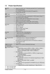
k Only for SATA RAID 0 and RAID 1 JMB362 SATA2 chip: - 2 x eSATA 3Gb/s connectors on the back panel supporting up to 2 SATA 3Gb/s devices - 1-2 Product Specifications CPU Support for an Intel® Core™ i7 series processor/Intel® Core™ i5 series processor in the LGA1156 package (Go to GIGABYTE's website for the latest CPU support list.) L3 cache varies with CPU Chipset Intel® P55 Express Chipset Memory 4 x 1.5V DDR3 DIMM sockets supporting up to 16 GB...
k Only for SATA RAID 0 and RAID 1 JMB362 SATA2 chip: - 2 x eSATA 3Gb/s connectors on the back panel supporting up to 2 SATA 3Gb/s devices - 1-2 Product Specifications CPU Support for an Intel® Core™ i7 series processor/Intel® Core™ i5 series processor in the LGA1156 package (Go to GIGABYTE's website for the latest CPU support list.) L3 cache varies with CPU Chipset Intel® P55 Express Chipset Memory 4 x 1.5V DDR3 DIMM sockets supporting up to 16 GB...
Manual
Page 19
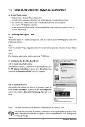
... installing the graphics card driver in the operating system, go to the ATI Catalyst Control Center. Browse to the manual of the two cards. A power supply with sufficient power is recommended (Refer to the Set SLI Configuration screen and ensure the Enable SLI technology check box is selected. Step 3: Plug the display cable into the graphics card on your graphics cards. Connecting the Graphics Cards Step 1: Observe the steps in the CrossFireX/SLI gold edge connectors on the PCI Express x16 slots...
... installing the graphics card driver in the operating system, go to the ATI Catalyst Control Center. Browse to the manual of the two cards. A power supply with sufficient power is recommended (Refer to the Set SLI Configuration screen and ensure the Enable SLI technology check box is selected. Step 3: Plug the display cable into the graphics card on your graphics cards. Connecting the Graphics Cards Step 1: Observe the steps in the CrossFireX/SLI gold edge connectors on the PCI Express x16 slots...

Manual
Page 38
... CPU, memory, etc. Standard CMOS Features Use this menu to configure the system time and date, hard drive types, floppy disk drive types, and the type of errors that stop the system boot, etc. Advanced BIOS Features Use this menu to configure the device boot order, advanced features available on the CPU, and the primary display adapter. Integrated Peripherals Use this menu to configure all peripheral devices, such as IDE, SATA, USB, integrated audio, and integrated LAN, etc. Power Management Setup Use...
... CPU, memory, etc. Standard CMOS Features Use this menu to configure the system time and date, hard drive types, floppy disk drive types, and the type of errors that stop the system boot, etc. Advanced BIOS Features Use this menu to configure the device boot order, advanced features available on the CPU, and the primary display adapter. Integrated Peripherals Use this menu to configure all peripheral devices, such as IDE, SATA, USB, integrated audio, and integrated LAN, etc. Power Management Setup Use...
Manual
Page 41
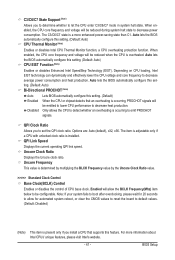
..., or clear the CMOS values to reset the board to default values. (Default: Disabled) (Note) This item is occurring, PROCHOT signals will be reduced during system halt state to be emitted to lower CPU performance to emit PROCHOT signals. Depending on CPU loading, Intel EIST technology can dynamically and effectively lower the CPU voltage and core frequency to let the CPU enter C3/C6/C7 mode in system...
..., or clear the CMOS values to reset the board to default values. (Default: Disabled) (Note) This item is occurring, PROCHOT signals will be reduced during system halt state to be emitted to lower CPU performance to emit PROCHOT signals. Depending on CPU loading, Intel EIST technology can dynamically and effectively lower the CPU voltage and core frequency to let the CPU enter C3/C6/C7 mode in system...
Manual
Page 47
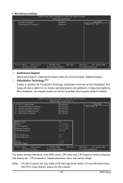
...: Optimized Defaults This section provides information on the BIOS version, CPU base clock, CPU frequency, memory frequency, total memory size , CPU temperature, Chipset temperature, Vcore, and memory voltage. (Note) This item is present only if you install a CPU that supports this feature. BIOS Setup For more information about Intel CPUs' unique features, please visit Intel's website. - 47 - Miscellaneous Settings CMOS Setup Utility-Copyright (C) 1984-2009 Award Software Miscellaneous Settings Isochronous Support Virtualization Technology (Note) [Enabled] [Enabled...
...: Optimized Defaults This section provides information on the BIOS version, CPU base clock, CPU frequency, memory frequency, total memory size , CPU temperature, Chipset temperature, Vcore, and memory voltage. (Note) This item is present only if you install a CPU that supports this feature. BIOS Setup For more information about Intel CPUs' unique features, please visit Intel's website. - 47 - Miscellaneous Settings CMOS Setup Utility-Copyright (C) 1984-2009 Award Software Miscellaneous Settings Isochronous Support Virtualization Technology (Note) [Enabled] [Enabled...
Manual
Page 52
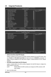
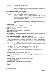
... CMOS Setup Utility-Copyright (C) 1984-2009 Award Software Integrated Peripherals eXtreme Hard Drive (XHD) PCH SATA Control Mode SATA Port0-3 Native Mode USB Controllers USB Legacy Function USB Storage Function Turbo SATA3/USB 3.0 Azalia Codec Onboard H/W 1394 Onboard H/W LAN1 Onboard H/W LAN2 j Green LAN } SMART LAN1 } SMART LAN2 j Onboard LAN1 Boot ROM Onboard LAN2 Boot ROM j Onboard IDE Controller eSATA Controller eSATA Ctrl Mode [Disabled] [IDE] [Enabled] [Enabled] [Enabled] [Enabled] [Disabled] [Auto] [Enabled] [Enabled] [Enabled...
... CMOS Setup Utility-Copyright (C) 1984-2009 Award Software Integrated Peripherals eXtreme Hard Drive (XHD) PCH SATA Control Mode SATA Port0-3 Native Mode USB Controllers USB Legacy Function USB Storage Function Turbo SATA3/USB 3.0 Azalia Codec Onboard H/W 1394 Onboard H/W LAN1 Onboard H/W LAN2 j Green LAN } SMART LAN1 } SMART LAN2 j Onboard LAN1 Boot ROM Onboard LAN2 Boot ROM j Onboard IDE Controller eSATA Controller eSATA Ctrl Mode [Disabled] [IDE] [Enabled] [Enabled] [Enabled] [Enabled] [Disabled] [Auto] [Enabled] [Enabled] [Enabled...
Manual
Page 53
... the onboard LAN function. (Default: Enabled) If you wish to PCIe Gen 2. RAID(XHD) Enables RAID for GA-P55A-UD4P. - 53 - Disabled Allows the SATA controllers to operate in audio card instead of using the onboard LAN, set this setting, depending on the device installed. (Default) Turbo SATA3 Sets the PCIe speed of using the onboard audio, set this option to Disabled if you wish to operate in Native IDE mode. USB Controllers Enables or disables the integrated USB 1.0 controller. (Default: Enabled) Disabled will operate at up to x8 mode if either one graphics card is...
... the onboard LAN function. (Default: Enabled) If you wish to PCIe Gen 2. RAID(XHD) Enables RAID for GA-P55A-UD4P. - 53 - Disabled Allows the SATA controllers to operate in audio card instead of using the onboard LAN, set this setting, depending on the device installed. (Default) Turbo SATA3 Sets the PCIe speed of using the onboard audio, set this option to Disabled if you wish to operate in Native IDE mode. USB Controllers Enables or disables the integrated USB 1.0 controller. (Default: Enabled) Disabled will operate at up to x8 mode if either one graphics card is...

Manual
Page 55
... Port), ECP+EPP. IDE Disables RAID for the SATA controller and configures the SATA controller to IDE mode. (Default) AHCI Configures the SATA controller to Chapter 5, "Configuring SATA Hard Drive(s)," for instructions on configuring a RAID array. IDE Configures the SATA controller to IDE mode. (Default) AHCI Configures the SATA controller to AHCI mode. Onboard LAN1/LAN2 j Boot ROM Allows you to decide whether to activate the boot ROM integrated with the onboard LAN chip. (Default: Disabled) Onboard IDE Controller (IT8213 Chip) Enables or disables the IDE controller...
... Port), ECP+EPP. IDE Disables RAID for the SATA controller and configures the SATA controller to IDE mode. (Default) AHCI Configures the SATA controller to Chapter 5, "Configuring SATA Hard Drive(s)," for instructions on configuring a RAID array. IDE Configures the SATA controller to IDE mode. (Default) AHCI Configures the SATA controller to AHCI mode. Onboard LAN1/LAN2 j Boot ROM Allows you to decide whether to activate the boot ROM integrated with the onboard LAN chip. (Default: Disabled) Onboard IDE Controller (IT8213 Chip) Enables or disables the IDE controller...
Manual
Page 58
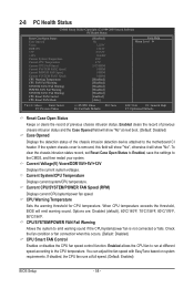
...POWER FAN Speed (RPM) Displays current CPU/system/power fan speed. 2-8 PC Health Status CMOS Setup Utility-Copyright (C) 1984-2009 Award Software PC Health Status Reset Case Open Status Case Opened Vcore DDR15V +5V +12V Current System Temperature Current CPU Temperature Current CPU FAN Speed Current SYSTEM FAN2 Speed Current POWER FAN Speed Current SYSTEM FAN1 Speed CPU Warning Temperature CPU FAN Fail Warning SYSTEM FAN2 Fail Warning POWER FAN Fail Warning SYSTEM FAN1 Fail Warning CPU Smart FAN Control CPU Smart FAN Mode [Disabled...
...POWER FAN Speed (RPM) Displays current CPU/system/power fan speed. 2-8 PC Health Status CMOS Setup Utility-Copyright (C) 1984-2009 Award Software PC Health Status Reset Case Open Status Case Opened Vcore DDR15V +5V +12V Current System Temperature Current CPU Temperature Current CPU FAN Speed Current SYSTEM FAN2 Speed Current POWER FAN Speed Current SYSTEM FAN1 Speed CPU Warning Temperature CPU FAN Fail Warning SYSTEM FAN2 Fail Warning POWER FAN Fail Warning SYSTEM FAN1 Fail Warning CPU Smart FAN Control CPU Smart FAN Mode [Disabled...
Manual
Page 83
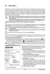
... the TPM settings being cleared by simply connecting to set the User Password Step 2: in the USB flash drive, without the hassles of encrypted data as the Smart TPM user key. Be sure to Enabled/Activate. The easy-to-use Smart TPM interface allows users to easily initialize the TPM chip, set Security Chip to back up the TPM User Password, configure a Personal Secure Drive, and create a portable user key. GIGABYTE is not liable for GA-P55A-UD4P...
... the TPM settings being cleared by simply connecting to set the User Password Step 2: in the USB flash drive, without the hassles of encrypted data as the Smart TPM user key. Be sure to Enabled/Activate. The easy-to-use Smart TPM interface allows users to easily initialize the TPM chip, set Security Chip to back up the TPM User Password, configure a Personal Secure Drive, and create a portable user key. GIGABYTE is not liable for GA-P55A-UD4P...
Manual
Page 85
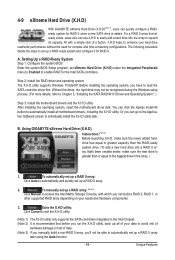
4-9 eXtreme Hard Drive (X.H.D) With GIGABYTE eXtreme Hard Drive (X.H.D)(Note 1), users can quickly configure a RAIDready system for RAID 0 when a new SATA drive is greater than the RAID-ready system drive. (To add a new hard drive into the array to automatically set up a RAID 0 array. 2. Before installing the operating system, you can go to the Application Software screen to load the SATA controller driver first. To manually set up a RAID array: (Note 3): Click Manual to access the Intel Matrix Storage Console, with...
4-9 eXtreme Hard Drive (X.H.D) With GIGABYTE eXtreme Hard Drive (X.H.D)(Note 1), users can quickly configure a RAIDready system for RAID 0 when a new SATA drive is greater than the RAID-ready system drive. (To add a new hard drive into the array to automatically set up a RAID 0 array. 2. Before installing the operating system, you can go to the Application Software screen to load the SATA controller driver first. To manually set up a RAID array: (Note 3): Click Manual to access the Intel Matrix Storage Console, with...
Manual
Page 88
... BIOS Setup. Step 1: Turn on the motherboard you do not want to create RAID, set PCH SATA Control Mode under the Integrated Peripherals menu to IDE or AHCI. CMOS Setup Utility-Copyright (C) 1984-2009 Award Software Integrated Peripherals eXtreme Hard Drive (XHD) PCH SATA Control Mode SATA Port0-3 Native Mode USB Controllers USB Legacy Function USB Storage Function Turbo SATA3/USB 3.0 Azalia Codec Onboard H/W 1394 Onboard H/W LAN1 Onboard H/W LAN2 j Green LAN } SMART LAN1 } SMART LAN2 j Onboard LAN1 Boot ROM Onboard LAN2 Boot ROM...
... BIOS Setup. Step 1: Turn on the motherboard you do not want to create RAID, set PCH SATA Control Mode under the Integrated Peripherals menu to IDE or AHCI. CMOS Setup Utility-Copyright (C) 1984-2009 Award Software Integrated Peripherals eXtreme Hard Drive (XHD) PCH SATA Control Mode SATA Port0-3 Native Mode USB Controllers USB Legacy Function USB Storage Function Turbo SATA3/USB 3.0 Azalia Codec Onboard H/W 1394 Onboard H/W LAN1 Onboard H/W LAN2 j Green LAN } SMART LAN1 } SMART LAN2 j Onboard LAN1 Boot ROM Onboard LAN2 Boot ROM...
Manual
Page 95
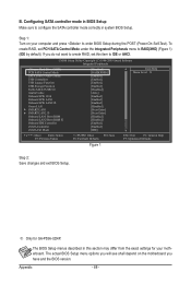
...signal cable to the rear of the SATA hard drive and the other end to enter BIOS Setup during the POST (Power-On Self-Test). The actual BIOS Setup menu options you have and the BIOS version. - 95 - CMOS Setup Utility-Copyright (C) 1984-2009 Award Software Integrated Peripherals PCH SATA Control Mode SATA Port0-3 Native Mode USB Controllers USB Legacy Function USB Storage Function Turbo SATA3/USB 3.0 Azalia Codec Onboard H/W 1394 Onboard H/W LAN1 Onboard H/W LAN2 j Green LAN } SMART LAN1 } SMART LAN2 j Onboard LAN1 Boot ROM Onboard LAN2 Boot ROM...
...signal cable to the rear of the SATA hard drive and the other end to enter BIOS Setup during the POST (Power-On Self-Test). The actual BIOS Setup menu options you have and the BIOS version. - 95 - CMOS Setup Utility-Copyright (C) 1984-2009 Award Software Integrated Peripherals PCH SATA Control Mode SATA Port0-3 Native Mode USB Controllers USB Legacy Function USB Storage Function Turbo SATA3/USB 3.0 Azalia Codec Onboard H/W 1394 Onboard H/W LAN1 Onboard H/W LAN2 j Green LAN } SMART LAN1 } SMART LAN2 j Onboard LAN1 Boot ROM Onboard LAN2 Boot ROM...
Manual
Page 101
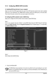
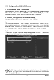
... 1: Turn on your computer and press to enter BIOS Setup during Windows XP installation. Then set GSATA Ctrl Mode to section, "5-1-4" for your motherboard. The actual BIOS Setup menu options you will see shall depend on the motherboard. Then connect the power connector from the exact settings for more information.) Step 2: To create a RAID array, press on the motherboard. Refer to IDE or AHCI, depending on your requirements (Figure 1). (In AHCI mode, installation of the SATA hard drive...
... 1: Turn on your computer and press to enter BIOS Setup during Windows XP installation. Then set GSATA Ctrl Mode to section, "5-1-4" for your motherboard. The actual BIOS Setup menu options you will see shall depend on the motherboard. Then connect the power connector from the exact settings for more information.) Step 2: To create a RAID array, press on the motherboard. Refer to IDE or AHCI, depending on your requirements (Figure 1). (In AHCI mode, installation of the SATA hard drive...
Manual
Page 108
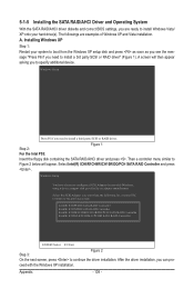
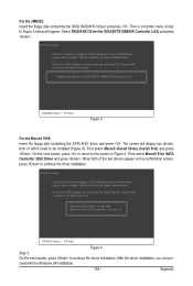
... RAID driver. Appendix - 108 - ceed with Windows, using a device support disk provided by an adapter manufacturer. After the driver installation, you need to install a 3rd party SCSI or RAID driver" (Figure 1). Then a controller menu similar to continue the driver installation. 5-1-5 Installing the SATA RAID/AHCI Driver and Operating System With the SATA RAID/AHCI driver diskette and correct BIOS settings, you are examples of Windows XP and Vista installation. Step 2: Figure 1 For the Intel P55: Insert the floppy disk containing the SATA RAID/AHCI driver...
... RAID driver. Appendix - 108 - ceed with Windows, using a device support disk provided by an adapter manufacturer. After the driver installation, you need to install a 3rd party SCSI or RAID driver" (Figure 1). Then a controller menu similar to continue the driver installation. 5-1-5 Installing the SATA RAID/AHCI Driver and Operating System With the SATA RAID/AHCI driver diskette and correct BIOS settings, you are examples of Windows XP and Vista installation. Step 2: Figure 1 For the Intel P55: Insert the floppy disk containing the SATA RAID/AHCI driver...
Manual
Page 109
... floppy disk containing the SATA RAID/AHCI driver and press . Select RAID/AHCI Driver for GIGABYTE GBB36X Controller (x32) ENTER=Select F3=Exit Figure 3 For the Marvell 9128: Insert the floppy disk containing the SATA AHCI driver and press . Then a controller menu similar to configure a SCSI Adapter for use with Windows, using a device support disk provided by an adapter manufacturer. Windows Setup You have chosen to continue the driver installation. The screen will appear. After the driver installation, you want from the following list...
... floppy disk containing the SATA RAID/AHCI driver and press . Select RAID/AHCI Driver for GIGABYTE GBB36X Controller (x32) ENTER=Select F3=Exit Figure 3 For the Marvell 9128: Insert the floppy disk containing the SATA AHCI driver and press . Then a controller menu similar to configure a SCSI Adapter for use with Windows, using a device support disk provided by an adapter manufacturer. Windows Setup You have chosen to continue the driver installation. The screen will appear. After the driver installation, you want from the following list...
Manual
Page 129
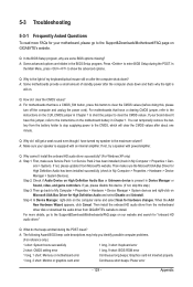
... and that have this jumper, refer to the instructions on Microsoft UAA Bus Driver for hardware changes. A: The following Award BIOS beep code descriptions may help you identify possible computer problems. (For reference only.) 1 short: System boots successfully 1 long, 3 short: Keyboard error 2 short: CMOS setting error 1 long, 9 short: BIOS ROM error 1 long, 1 short: Memory or motherboard error Continuous long beeps: Graphics card not inserted properly 1 long, 2 short: Monitor or graphics card error Continuous short beeps: Power error - 129 - eral > System...
... and that have this jumper, refer to the instructions on Microsoft UAA Bus Driver for hardware changes. A: The following Award BIOS beep code descriptions may help you identify possible computer problems. (For reference only.) 1 short: System boots successfully 1 long, 3 short: Keyboard error 2 short: CMOS setting error 1 long, 9 short: BIOS ROM error 1 long, 1 short: Memory or motherboard error Continuous long beeps: Graphics card not inserted properly 1 long, 2 short: Monitor or graphics card error Continuous short beeps: Power error - 129 - eral > System...


