
Manual
Page 1
...depending on your needs and hardware components. 3. To automatically set up a RAID 0 array later using the Auto function. eXtreme Hard Drive (X.H.D) With GIGABYTE eXtreme Hard Drive (X.H.D)(Note 1), users can use X.H.D to easily add a hard drive into a RAID 0 array that's been created earlier, make...Integrated Peripherals menu to Enabled to individually install the X.H.D utility later. Setting Up a RAID-Ready System Step 1: Configure the system BIOS Enter the system BIOS Setup program, set up a RAID 0 array: Click Auto to load the SATA controller driver first. You can go to the...
...depending on your needs and hardware components. 3. To automatically set up a RAID 0 array later using the Auto function. eXtreme Hard Drive (X.H.D) With GIGABYTE eXtreme Hard Drive (X.H.D)(Note 1), users can use X.H.D to easily add a hard drive into a RAID 0 array that's been created earlier, make...Integrated Peripherals menu to Enabled to individually install the X.H.D utility later. Setting Up a RAID-Ready System Step 1: Configure the system BIOS Enter the system BIOS Setup program, set up a RAID 0 array: Click Auto to load the SATA controller driver first. You can go to the...
Manual
Page 3
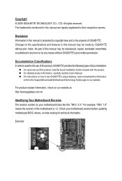
... our website. For instructions on your motherboard revision before updating motherboard BIOS, drivers, or when looking for technical information. Check your motherboard looks like this manual may be made by GIGABYTE without GIGABYTE's prior written permission. No part of this manual are legally registered..., transmitted, or published in this : "REV: X.X." For product-related information, check on our website at: http://www.gigabyte.com.tw Identifying Your Motherboard Revision The revision number on how to their respective owners. The trademarks mentioned in the use...
... our website. For instructions on your motherboard revision before updating motherboard BIOS, drivers, or when looking for technical information. Check your motherboard looks like this manual may be made by GIGABYTE without GIGABYTE's prior written permission. No part of this manual are legally registered..., transmitted, or published in this : "REV: X.X." For product-related information, check on our website at: http://www.gigabyte.com.tw Identifying Your Motherboard Revision The revision number on how to their respective owners. The trademarks mentioned in the use...
Manual
Page 4
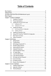
Table of Contents Box Contents...6 Optional Items...6 GA-P55A-UD4P/GA-P55A-UD4 Motherboard Layout 7 Block Diagram...8 Chapter 1 Hardware Installation 9 1-1 Installation Precautions 9 1-2 Product Specifications 10 1-3 Installing the CPU and CPU Cooler 13...;/NVIDIA SLI Configuration 19 1-7 Back Panel Connectors 20 1-8 Internal Connectors 22 Chapter 2 BIOS Setup 35 2-1 Startup Screen 36 2-2 The Main Menu 37 2-3 MB Intelligent Tweaker(M.I.T 39 2-4 Standard CMOS Features 48 2-5 Advanced BIOS Features 50 2-6 Integrated Peripherals 52 2-7 Power Management Setup 56 2-8 PC Health Status ...
Table of Contents Box Contents...6 Optional Items...6 GA-P55A-UD4P/GA-P55A-UD4 Motherboard Layout 7 Block Diagram...8 Chapter 1 Hardware Installation 9 1-1 Installation Precautions 9 1-2 Product Specifications 10 1-3 Installing the CPU and CPU Cooler 13...;/NVIDIA SLI Configuration 19 1-7 Back Panel Connectors 20 1-8 Internal Connectors 22 Chapter 2 BIOS Setup 35 2-1 Startup Screen 36 2-2 The Main Menu 37 2-3 MB Intelligent Tweaker(M.I.T 39 2-4 Standard CMOS Features 48 2-5 Advanced BIOS Features 50 2-6 Integrated Peripherals 52 2-7 Power Management Setup 56 2-8 PC Health Status ...

Manual
Page 5
3-4 Contact...67 3-5 System...67 3-6 Download Center 68 3-7 New Utilities...68 Chapter 4 Unique Features 69 4-1 Xpress Recovery2 69 4-2 BIOS Update Utilities 72 4-2-1 Updating the BIOS with the Q-Flash Utility 72 4-2-2 Updating the BIOS with the @BIOS Utility 75 4-3 EasyTune 6...76 4-4 Dynamic Energy Saver™ 2 77 4-5 Q-Share...79 4-6 Smart 6™...80 4-7 Smart TPM j... Recording 126 5-2-5 Using the Sound Recorder 128 5-3 Troubleshooting 129 5-3-1 Frequently Asked Questions 129 5-3-2 Troubleshooting Procedure 130 5-4 Regulatory Statements 132 j Only for GA-P55A-UD4P. - 5 -
3-4 Contact...67 3-5 System...67 3-6 Download Center 68 3-7 New Utilities...68 Chapter 4 Unique Features 69 4-1 Xpress Recovery2 69 4-2 BIOS Update Utilities 72 4-2-1 Updating the BIOS with the Q-Flash Utility 72 4-2-2 Updating the BIOS with the @BIOS Utility 75 4-3 EasyTune 6...76 4-4 Dynamic Energy Saver™ 2 77 4-5 Q-Share...79 4-6 Smart 6™...80 4-7 Smart TPM j... Recording 126 5-2-5 Using the Sound Recorder 128 5-3 Troubleshooting 129 5-3-1 Frequently Asked Questions 129 5-3-2 Troubleshooting Procedure 130 5-4 Regulatory Statements 132 j Only for GA-P55A-UD4P. - 5 -
Manual
Page 8
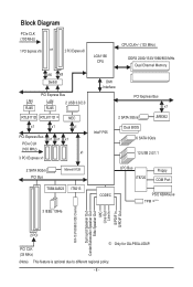
... CLK+/- (133 MHz) DDR3 2200/1333/1066/800 MHz Dual Channel Memory DMI Interface PCI Express Bus x1 2 SATA 3Gb/s JMB362 Intel® P55 Dual BIOS 6 SATA 3Gb/s 12 USB 2.0/1.1 LPC Bus IT8720 Floppy COM Port CODEC PS/2 KB/Mouse TPM j(Note) ATA-133/100/66/33 IDE Channel Surround Speaker... Out Center/Subwoofer Speaker Out Side Speaker Out MIC Line Out Line In S/PDIF In S/PDIF Out 2 PCI PCI CLK (33 MHz) j Only for GA-P55A-UD4P. (Note) This feature is optional due to different regional policy. - 8 -
... CLK+/- (133 MHz) DDR3 2200/1333/1066/800 MHz Dual Channel Memory DMI Interface PCI Express Bus x1 2 SATA 3Gb/s JMB362 Intel® P55 Dual BIOS 6 SATA 3Gb/s 12 USB 2.0/1.1 LPC Bus IT8720 Floppy COM Port CODEC PS/2 KB/Mouse TPM j(Note) ATA-133/100/66/33 IDE Channel Surround Speaker... Out Center/Subwoofer Speaker Out Side Speaker Out MIC Line Out Line In S/PDIF In S/PDIF Out 2 PCI PCI CLK (33 MHz) j Only for GA-P55A-UD4P. (Note) This feature is optional due to different regional policy. - 8 -
Manual
Page 12
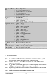
... Available functions in the PCIEX16 slot (Note 3) The PCIEX8 slot shares bandwidth with the PCIEX16 slot. Hardware Installation - 12 - Hardware Monitor w w w w w w BIOS w w w w Unique Features w w w w w w w w w w w w w Bundled Software w System voltage detection CPU/System temperature detection CPU/System/Power...XP Form Factor w ATX Form Factor; 30.5cm x 24.4cm j Only for GA-P55A-UD4P. (Note 1) Due to install it in EasyTune may differ by motherboard model.
... Available functions in the PCIEX16 slot (Note 3) The PCIEX8 slot shares bandwidth with the PCIEX16 slot. Hardware Installation - 12 - Hardware Monitor w w w w w w BIOS w w w w Unique Features w w w w w w w w w w w w w Bundled Software w System voltage detection CPU/System temperature detection CPU/System/Power...XP Form Factor w ATX Form Factor; 30.5cm x 24.4cm j Only for GA-P55A-UD4P. (Note 1) Due to install it in EasyTune may differ by motherboard model.
Manual
Page 16
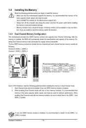
.... 1-4-1 Dual Channel Memory Configuration This motherboard provides four DDR3 memory sockets and supports Dual Channel Technology. If only one DDR3 memory module is installed, the BIOS will double the original memory bandwidth. A memory module can be sure to GIGABYTE's website for optimum performance. Hardware Installation - 16 - After the memory is installed. 2.
.... 1-4-1 Dual Channel Memory Configuration This motherboard provides four DDR3 memory sockets and supports Dual Channel Technology. If only one DDR3 memory module is installed, the BIOS will double the original memory bandwidth. A memory module can be sure to GIGABYTE's website for optimum performance. Hardware Installation - 16 - After the memory is installed. 2.
Manual
Page 18
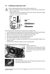
Remove the metal slot cover from the slot. Make sure the metal contacts on your card. If necessary, go to BIOS Setup to make any required BIOS changes for your expansion card. • Always turn off the computer and unplug the power cord from the power outlet before you begin to install ...
Remove the metal slot cover from the slot. Make sure the metal contacts on your card. If necessary, go to BIOS Setup to make any required BIOS changes for your expansion card. • Always turn off the computer and unplug the power cord from the power outlet before you begin to install ...

Manual
Page 27
...HD+ HD- This function requires a chassis with a chassis intrusion switch/sensor. When connecting your system using the power switch (refer to Chapter 2, "BIOS Setup," "Power Management Setup," for information about beep codes. • HD (Hard Drive Activity LED, Blue) Connects to the pin assignments below. Note...the reset switch on the chassis front panel. The system reports system startup status by chassis. S1 Blinking tem is detected, the BIOS may differ by issuing a beep code. If a problem is in different patterns to this header according to the hard drive ...
...HD+ HD- This function requires a chassis with a chassis intrusion switch/sensor. When connecting your system using the power switch (refer to Chapter 2, "BIOS Setup," "Power Management Setup," for information about beep codes. • HD (Hard Drive Activity LED, Blue) Connects to the pin assignments below. Note...the reset switch on the chassis front panel. The system reports system startup status by chassis. S1 Blinking tem is detected, the BIOS may differ by issuing a beep code. If a problem is in different patterns to this header according to the hard drive ...
Manual
Page 32
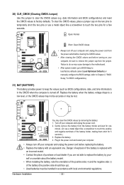
... the power cord before turning on the two pins to temporarily short the two pins or use a metal object like a screwdriver to Chapter 2, "BIOS Setup," for 5 seconds.) 3. Open: Normal Short: Clear CMOS Values • Always turn off your computer and unplug the power cord from the...values. • After clearing the CMOS values and before replacing the battery. • Replace the battery with local environmental regulations. date information and BIOS configurations) and reset the CMOS values to clear the CMOS values (e.g. To clear the CMOS values, place a jumper cap on your - You ...
... the power cord before turning on the two pins to temporarily short the two pins or use a metal object like a screwdriver to Chapter 2, "BIOS Setup," for 5 seconds.) 3. Open: Normal Short: Clear CMOS Values • Always turn off your computer and unplug the power cord from the...values. • After clearing the CMOS values and before replacing the battery. • Replace the battery with local environmental regulations. date information and BIOS configurations) and reset the CMOS values to clear the CMOS values (e.g. To clear the CMOS values, place a jumper cap on your - You ...
Manual
Page 35
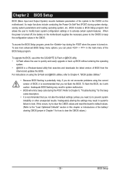
...to Chapter 4, "BIOS Update Utilities." • Because BIOS flashing is potentially risky, if you do it is a Windows-based utility that you not flash the BIOS. To upgrade the BIOS, use either the GIGABYTE Q-Flash or @BIOS utility. • Q-Flash allows the user to boot. BIOS Setup When the power... is turned off, the battery on . To access the BIOS Setup program, press the key during system ...
...to Chapter 4, "BIOS Update Utilities." • Because BIOS flashing is potentially risky, if you do it is a Windows-based utility that you not flash the BIOS. To upgrade the BIOS, use either the GIGABYTE Q-Flash or @BIOS utility. • Q-Flash allows the user to boot. BIOS Setup When the power... is turned off, the battery on . To access the BIOS Setup program, press the key during system ...
Manual
Page 36
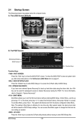
...BIOS Version P55A-UD4P D20 . . . . : BIOS Setup : XpressRecovery2 : Boot Menu : Qflash 09/23/2009-P55-7A89RG0WC-00 Function Keys Function Keys Function Keys: : POST SCREEN Press the key to show the BIOS POST screen at system startup, refer to the instructions on the Full Screen LOGO Show item on BIOS...without having to Xpress Recovery2 during the POST. 2-1 Startup Screen The following screens may appear when the computer boots. A. To show the BIOS POST screen. Note: The setting in Boot Menu. The LOGO Screen (Default) B. In Boot Menu, use the up hard drive ...
...BIOS Version P55A-UD4P D20 . . . . : BIOS Setup : XpressRecovery2 : Boot Menu : Qflash 09/23/2009-P55-7A89RG0WC-00 Function Keys Function Keys Function Keys: : POST SCREEN Press the key to show the BIOS POST screen at system startup, refer to the instructions on the Full Screen LOGO Show item on BIOS...without having to Xpress Recovery2 during the POST. 2-1 Startup Screen The following screens may appear when the computer boots. A. To show the BIOS POST screen. Note: The setting in Boot Menu. The LOGO Screen (Default) B. In Boot Menu, use the up hard drive ...
Manual
Page 37
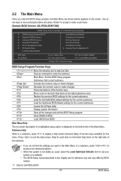
...current submenus Access the Q-Flash utility Display system information Save all the changes and exit the BIOS Setup program Save CMOS to exit the help screen (General Help) of function keys available for GA-P55A-UD4P. - 37 - Use arrow keys to move among the items and press to ...accept or enter a sub-menu. (Sample BIOS Version: GA-P55A-UD4P D20) CMOS Setup Utility-Copyright (C) 1984-2009 Award Software MB...
...current submenus Access the Q-Flash utility Display system information Save all the changes and exit the BIOS Setup program Save CMOS to exit the help screen (General Help) of function keys available for GA-P55A-UD4P. - 37 - Use arrow keys to move among the items and press to ...accept or enter a sub-menu. (Sample BIOS Version: GA-P55A-UD4P D20) CMOS Setup Utility-Copyright (C) 1984-2009 Award Software MB...

Manual
Page 38
...MB Intelligent Tweaker(M.I.T.) Use this menu to configure the clock, frequency and voltages of your system becomes unstable and you have loaded the BIOS default settings, you can also carry out this task.) Security Chip Configuration j Use this task.) Exit Without ...for the most stable, minimal-performance system operations. Load Optimized Defaults Optimized defaults are factory settings for GA-P55A-UD4P. Pressing to the confirmation message will exit BIOS Setup. (Pressing can use the SPACE key) and then press to complete. F12: Load CMOS from...
...MB Intelligent Tweaker(M.I.T.) Use this menu to configure the clock, frequency and voltages of your system becomes unstable and you have loaded the BIOS default settings, you can also carry out this task.) Security Chip Configuration j Use this task.) Exit Without ...for the most stable, minimal-performance system operations. Load Optimized Defaults Optimized defaults are factory settings for GA-P55A-UD4P. Pressing to the confirmation message will exit BIOS Setup. (Pressing can use the SPACE key) and then press to complete. F12: Load CMOS from...
Manual
Page 39
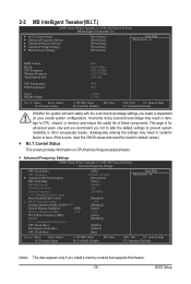
... doing overclock/overvoltage may result in damage to default values.) M.I.T. If this feature. - 39 - BIOS Setup This page is dependent on CPU/memory frequencies/parameters. Advanced Frequency Settings CMOS Setup Utility-Copyright (C)... Voltage Settings } Miscellaneous Settings [Press Enter] [Press Enter] [Press Enter] [Press Enter] [Press Enter] Item Help Menu Level BIOS Version BCLK CPU Frequency Memory Frequency Total Memory Size D20 136.73 MHz 2871.41 MHz 1367.27 MHz 2048 MB CPU Temperature PCH Temperature...
... doing overclock/overvoltage may result in damage to default values.) M.I.T. If this feature. - 39 - BIOS Setup This page is dependent on CPU/memory frequencies/parameters. Advanced Frequency Settings CMOS Setup Utility-Copyright (C)... Voltage Settings } Miscellaneous Settings [Press Enter] [Press Enter] [Press Enter] [Press Enter] [Press Enter] Item Help Menu Level BIOS Version BCLK CPU Frequency Memory Frequency Total Memory Size D20 136.73 MHz 2871.41 MHz 1367.27 MHz 2048 MB CPU Temperature PCH Temperature...
Manual
Page 40
...General Help F7: Optimized Defaults Intel(R) Turbo Boost Tech. This feature only works for the installed CPU. BIOS Setup - 40 - All Enables all CPU cores. Auto lets the BIOS automatically configure this setting. (Default: Auto) (Note) This item is dependent on the CPU being installed....CPU core frequency and voltage will be reduced during system halt state to enable the Intel CPU Turbo Boost technology. Auto lets the BIOS automatically configure this setting. (Default: Auto) CPU Cores Enabled (Note) Allows you to determine whether to decrease power consumption. The...
...General Help F7: Optimized Defaults Intel(R) Turbo Boost Tech. This feature only works for the installed CPU. BIOS Setup - 40 - All Enables all CPU cores. Auto lets the BIOS automatically configure this setting. (Default: Auto) (Note) This item is dependent on the CPU being installed....CPU core frequency and voltage will be reduced during system halt state to enable the Intel CPU Turbo Boost technology. Auto lets the BIOS automatically configure this setting. (Default: Auto) CPU Cores Enabled (Note) Allows you to determine whether to decrease power consumption. The...
Manual
Page 41
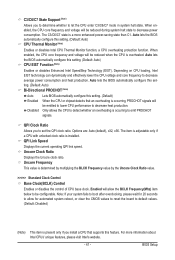
...: Auto) CPU EIST Function (Note) Enables or disables Enhanced Intel SpeedStep Technology (EIST). Uncore Frequency This value is installed. BIOS Setup C3/C6/C7 State Support (Note) Allows you to determine whether to emit PROCHOT signals. abled, the CPU core frequency...Intel CPU Thermal Monitor function, a CPU overheating protection function. ting. (Default: Auto) Bi-Directional PROCHOT (Note) Auto Enabled Disabled Lets BIOS automatically configure this setting. (Default) When the CPU or chipset detects that supports this set the QPI clock ratio. QPI Clock Ratio ...
...: Auto) CPU EIST Function (Note) Enables or disables Enhanced Intel SpeedStep Technology (EIST). Uncore Frequency This value is installed. BIOS Setup C3/C6/C7 State Support (Note) Allows you to determine whether to emit PROCHOT signals. abled, the CPU core frequency...Intel CPU Thermal Monitor function, a CPU overheating protection function. ting. (Default: Auto) Bi-Directional PROCHOT (Note) Auto Enabled Disabled Lets BIOS automatically configure this setting. (Default) When the CPU or chipset detects that supports this set the QPI clock ratio. QPI Clock Ratio ...

Manual
Page 42
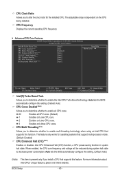
... Frequency(Mhz) The first memory frequency value is designed to automatically adjust CPU computing power to maximize system performance. Extreme Memory Profile (X.M.P.) (Note) Allows the BIOS to read the SPD data on system components, when system instability occurs after overclocking, lower the overclocking ratio. >>>>> Advanced Clock Control CPU Clock Drive Allows... Increases CPU frequency by 9% or 11% depending on your system hardware components. As stability is enabled. PCI Express Clock Drive Allows you to 150 MHz. BIOS Setup - 42 -
... Frequency(Mhz) The first memory frequency value is designed to automatically adjust CPU computing power to maximize system performance. Extreme Memory Profile (X.M.P.) (Note) Allows the BIOS to read the SPD data on system components, when system instability occurs after overclocking, lower the overclocking ratio. >>>>> Advanced Clock Control CPU Clock Drive Allows... Increases CPU frequency by 9% or 11% depending on your system hardware components. As stability is enabled. PCI Express Clock Drive Allows you to 150 MHz. BIOS Setup - 42 -
Manual
Page 43
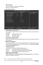
... is the memory frequency that supports this function. (Default) Profile1 Uses Profile 1 settings. Performance Enhance Allows the system to enhance memory performance when enabled. BIOS Setup CPU Clock Skew Allows you to set the system memory multiplier. Options are : Auto (default), Quick, Expert. (Note) This item appears only ... +/-/PU/PD: Value F10: Save F6: Fail-Safe Defaults ESC: Exit F1: General Help F7: Optimized Defaults Extreme Memory Profile (X.M.P.) (Note) Allows the BIOS to read the SPD data on XMP memory module(s) to operate at three different performance levels.
... is the memory frequency that supports this function. (Default) Profile1 Uses Profile 1 settings. Performance Enhance Allows the system to enhance memory performance when enabled. BIOS Setup CPU Clock Skew Allows you to set the system memory multiplier. Options are : Auto (default), Quick, Expert. (Note) This item appears only ... +/-/PU/PD: Value F10: Save F6: Fail-Safe Defaults ESC: Exit F1: General Help F7: Optimized Defaults Extreme Memory Profile (X.M.P.) (Note) Allows the BIOS to read the SPD data on XMP memory module(s) to operate at three different performance levels.

Manual
Page 44
... display the value based on the SPD data on the CPU being used. tRCD Options are : Auto (default), 1~63. Channel Interleaving Options are: Auto (default), 1~6. BIOS Setup - 44 - Profile DDR Voltage When using a non-XMP memory module or Extreme Memory Profile (X.M.P.) is set to Disabled, this item will display as 1.5V.
... display the value based on the SPD data on the CPU being used. tRCD Options are : Auto (default), 1~63. Channel Interleaving Options are: Auto (default), 1~6. BIOS Setup - 44 - Profile DDR Voltage When using a non-XMP memory module or Extreme Memory Profile (X.M.P.) is set to Disabled, this item will display as 1.5V.


