
Manual
Page 1
... the X.H.D utility. (Note 1) The X.H.D utility only supports the SATA controllers integrated in the array. ) 1. eXtreme Hard Drive (X.H.D) With GIGABYTE eXtreme Hard Drive (X.H.D)(Note 1), users can quickly configure a RAIDready system for complex and time-consuming configurations. Step 2: Install the RAID driver and... hardware components. 3. Without the driver, the hard drive may not be able to automatically install all of data. (Note 3) If you manually build a non-RAID 0 array, you run the X.H.D utility, back up a RAID 0 array. 2. The following procedure details the steps...
... the X.H.D utility. (Note 1) The X.H.D utility only supports the SATA controllers integrated in the array. ) 1. eXtreme Hard Drive (X.H.D) With GIGABYTE eXtreme Hard Drive (X.H.D)(Note 1), users can quickly configure a RAIDready system for complex and time-consuming configurations. Step 2: Install the RAID driver and... hardware components. 3. Without the driver, the hard drive may not be able to automatically install all of data. (Note 3) If you manually build a non-RAID 0 array, you run the X.H.D utility, back up a RAID 0 array. 2. The following procedure details the steps...
Manual
Page 1
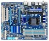
GA-P55A-UD4P GA-P55A-UD4 LGA1156 socket motherboard for Intel® Core™ i7 processor family/ Intel® Core™ i5 processor family User's Manual Rev. 1002 12ME-P55AU4P-1002R
GA-P55A-UD4P GA-P55A-UD4 LGA1156 socket motherboard for Intel® Core™ i7 processor family/ Intel® Core™ i5 processor family User's Manual Rev. 1002 12ME-P55AU4P-1002R
Manual
Page 3
... and is 1.0. The trademarks mentioned in this manual are legally registered to the specifications and features in this manual may be reproduced, copied, translated, transmitted, or published in the use GIGABYTE's unique features, read the User's Manual. Changes to their respective owners. For detailed ...\Motherboard\Technology Guide page on our website. Check your motherboard looks like this product, GIGABYTE provides the following types of documentations: For quick set-up of this manual may be made by any means without prior notice. No part of the product, ...
... and is 1.0. The trademarks mentioned in this manual are legally registered to the specifications and features in this manual may be reproduced, copied, translated, transmitted, or published in the use GIGABYTE's unique features, read the User's Manual. Changes to their respective owners. For detailed ...\Motherboard\Technology Guide page on our website. Check your motherboard looks like this product, GIGABYTE provides the following types of documentations: For quick set-up of this manual may be made by any means without prior notice. No part of the product, ...
Manual
Page 4
Table of Contents Box Contents...6 Optional Items...6 GA-P55A-UD4P/GA-P55A-UD4 Motherboard Layout 7 Block Diagram...8 Chapter 1 Hardware Installation 9 1-1 Installation Precautions 9 1-2 Product Specifications 10 1-3 Installing the CPU and CPU Cooler 13 1-3-1 Installing the CPU 13 1-3-2 Installing the ... & Exit Setup 62 2-13 Exit Without Saving 62 2-14 Security Chip Configuration j 63 Chapter 3 Drivers Installation 65 3-1 Installing Chipset Drivers 65 3-2 Application Software 66 3-3 Technical Manuals 66 - 4 -
Table of Contents Box Contents...6 Optional Items...6 GA-P55A-UD4P/GA-P55A-UD4 Motherboard Layout 7 Block Diagram...8 Chapter 1 Hardware Installation 9 1-1 Installation Precautions 9 1-2 Product Specifications 10 1-3 Installing the CPU and CPU Cooler 13 1-3-1 Installing the CPU 13 1-3-2 Installing the ... & Exit Setup 62 2-13 Exit Without Saving 62 2-14 Security Chip Configuration j 63 Chapter 3 Drivers Installation 65 3-1 Installing Chipset Drivers 65 3-2 Application Software 66 3-3 Technical Manuals 66 - 4 -
Manual
Page 6
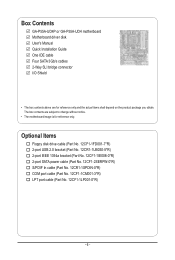
The box contents are for reference only. Box Contents GA-P55A-UD4P or GA-P55A-UD4 motherboard Motherboard driver disk User's Manual Quick Installation Guide One IDE cable Four SATA 3Gb/s cables 2-Way SLI bridge connector I/O Shield • The box contents above are subject to change without ...
The box contents are for reference only. Box Contents GA-P55A-UD4P or GA-P55A-UD4 motherboard Motherboard driver disk User's Manual Quick Installation Guide One IDE cable Four SATA 3Gb/s cables 2-Way SLI bridge connector I/O Shield • The box contents above are subject to change without ...
Manual
Page 9
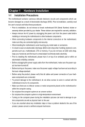
... or connectors. • It is best to wear an electrostatic discharge (ESD) wrist strap when handling electronic com- Prior to installation, carefully read the user's manual and follow these procedures: • Prior to installation, do not remove or break motherboard S/N (Serial Number) sticker or warranty sticker provided by unplugging the power...
... or connectors. • It is best to wear an electrostatic discharge (ESD) wrist strap when handling electronic com- Prior to installation, carefully read the user's manual and follow these procedures: • Prior to installation, do not remove or break motherboard S/N (Serial Number) sticker or warranty sticker provided by unplugging the power...
Manual
Page 15
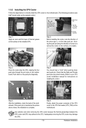
Check that the Male and Female push pins are joined closely. (Refer to your CPU cooler installation manual for instructions on installing the cooler.) Step 5: After the installation, check the back of the CPU cooler to the CPU fan header (CPU_FAN) on the ...
Check that the Male and Female push pins are joined closely. (Refer to your CPU cooler installation manual for instructions on installing the cooler.) Step 5: After the installation, check the back of the CPU cooler to the CPU fan header (CPU_FAN) on the ...
Manual
Page 18
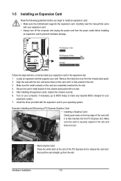
... on the top edge of the PCI Express slot to the chassis back panel with the expansion card in your expansion card(s). 7. Carefully read the manual that supports your expansion card. • Always turn off the computer and unplug the power cord from the chassis back panel. 2. Align the card with...
... on the top edge of the PCI Express slot to the chassis back panel with the expansion card in your expansion card(s). 7. Carefully read the manual that supports your expansion card. • Always turn off the computer and unplug the power cord from the chassis back panel. 2. Align the card with...
Manual
Page 19
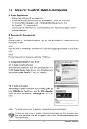
...and chip and correct driver - To Enable SLI Function After installing the graphics card driver in the operating system, go to the manual that came with your graphics cards for more information about enabling CrossFireX/SLI technology. - 19 - Hardware Installation C-2. Browse to the... manual of ATI CrossFireX™/NVIDIA SLI Configuration A. Connecting the Graphics Cards Step 1: Observe the steps in the CrossFireX/SLI gold edge ...
...and chip and correct driver - To Enable SLI Function After installing the graphics card driver in the operating system, go to the manual that came with your graphics cards for more information about enabling CrossFireX/SLI technology. - 19 - Hardware Installation C-2. Browse to the... manual of ATI CrossFireX™/NVIDIA SLI Configuration A. Connecting the Graphics Cards Step 1: Observe the steps in the CrossFireX/SLI gold edge ...

Manual
Page 29
... cable (provided by expansion cards) for digital audio output from your expansion card. For information about connecting the S/PDIF digital audio cable, carefully read the manual for digital audio output from your motherboard to your graphics card if you wish to connect an HDMI display to an audio device that supports...
... cable (provided by expansion cards) for digital audio output from your expansion card. For information about connecting the S/PDIF digital audio cable, carefully read the manual for digital audio output from your motherboard to your graphics card if you wish to connect an HDMI display to an audio device that supports...
Manual
Page 32
... do so may cause damage to the motherboard. • After system restart, go to BIOS Setup to load factory defaults (select Load Optimized Defaults) or manually configure the BIOS settings (refer to Chapter 2, "BIOS Setup," for 5 seconds.) 3.
... do so may cause damage to the motherboard. • After system restart, go to BIOS Setup to load factory defaults (select Load Optimized Defaults) or manually configure the BIOS settings (refer to Chapter 2, "BIOS Setup," for 5 seconds.) 3.

Manual
Page 42
.... Disabled Disables the use of C.I .A.2 allows your system bus to be set in accordance with the CPU specifications. PCI Express Clock Drive Allows you to manually set the PCIe clock frequency. Disabled Disables this feature. Auto sets the PCIe clock frequency to standard 100 MHz. (Default: Auto) C.I.A.2 CPU Intelligent Accelerator 2 (C.I .A.2, please... system performance. BCLK Frequency(Mhz) Allows you to set the system memory multiplier. Profile2 (Note) Uses Profile 2 settings. System Memory Multiplier (SPD) Allows you to manually set the CPU base clock.
.... Disabled Disables the use of C.I .A.2 allows your system bus to be set in accordance with the CPU specifications. PCI Express Clock Drive Allows you to manually set the PCIe clock frequency. Disabled Disables this feature. Auto sets the PCIe clock frequency to standard 100 MHz. (Default: Auto) C.I.A.2 CPU Intelligent Accelerator 2 (C.I .A.2, please... system performance. BCLK Frequency(Mhz) Allows you to set the system memory multiplier. Profile2 (Note) Uses Profile 2 settings. System Memory Multiplier (SPD) Allows you to manually set the CPU base clock.
Manual
Page 49
...detects a non-fatal error the system boot will skip the detection of the device during the POST for faster system startup. • Manual Allows you to None. Memory These fields are read-only and are determined by using one of the hard drive when the hard drive...this item to the information on the hard drive. Capacity Approximate capacity of extended memory. Drive A Allows you wish to enter the parameters manually, refer to None so the system will be reserved for an error during the POST. Typically, 640 KB will skip the detection of...
...detects a non-fatal error the system boot will skip the detection of the device during the POST for faster system startup. • Manual Allows you to None. Memory These fields are read-only and are determined by using one of the hard drive when the hard drive...this item to the information on the hard drive. Capacity Approximate capacity of extended memory. Drive A Allows you wish to enter the parameters manually, refer to None so the system will be reserved for an error during the POST. Typically, 640 KB will skip the detection of...
Manual
Page 65
...; For USB 2.0 driver support under the Windows XP operating system, please install the Windows XP Service Pack 1 or later. Or click Install Single Items to manually select the drivers you wish to restart your system automatically during the driver installation. You can click the Install All button and "Xpress Install" will...
...; For USB 2.0 driver support under the Windows XP operating system, please install the Windows XP Service Pack 1 or later. Or click Install Single Items to manually select the drivers you wish to restart your system automatically during the driver installation. You can click the Install All button and "Xpress Install" will...
Manual
Page 66
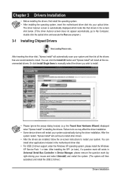
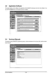
3-2 Application Software This page displays all the utilities and applications that GIGABYTE develops and some free software. Drivers Installation - 66 - You can click the Install button on the right of an item to install it. 3-3 Technical Manuals This page provides GIGABYTE's application guides, content descriptions for this driver disk, and the motherboard manuals.
3-2 Application Software This page displays all the utilities and applications that GIGABYTE develops and some free software. Drivers Installation - 66 - You can click the Install button on the right of an item to install it. 3-3 Technical Manuals This page provides GIGABYTE's application guides, content descriptions for this driver disk, and the motherboard manuals.
Manual
Page 72
...the BIOS with caution. What is DualBIOS™? p55aud4p.f1) to enter Q-Flash. P55A-UD4P D20 . . . . : BIOS Setup : XpressRecovery2 : Boot Menu : ... the hassles of going through complicated BIOS flashing process. From GIGABYTE's website, download the latest compressed BIOS update file that support...BIOS, the Q-Flash tool frees you to access Q-Flash. GIGABYTE Q-Flash and @BIOS are easy-to-use FAT32/16/12 ...is Q-Flash™? site and update the BIOS. 4-2 BIOS Update Utilities GIGABYTE motherboards provide two unique BIOS update tools, Q-Flash™ and @BIOS&#...
...the BIOS with caution. What is DualBIOS™? p55aud4p.f1) to enter Q-Flash. P55A-UD4P D20 . . . . : BIOS Setup : XpressRecovery2 : Boot Menu : ... the hassles of going through complicated BIOS flashing process. From GIGABYTE's website, download the latest compressed BIOS update file that support...BIOS, the Q-Flash tool frees you to access Q-Flash. GIGABYTE Q-Flash and @BIOS are easy-to-use FAT32/16/12 ...is Q-Flash™? site and update the BIOS. 4-2 BIOS Update Utilities GIGABYTE motherboards provide two unique BIOS update tools, Q-Flash™ and @BIOS&#...
Manual
Page 75
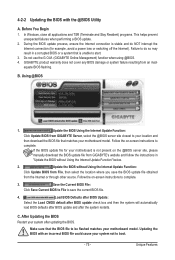
... system failure resulting from GIGABYTE Server, select the @BIOS server site closest to boot. - 75 - Follow the on -screen instructions to do NOT interrupt the Internet connection (for your motherboard is not present on the @BIOS server site, please manually download the BIOS update ...in a corrupted BIOS or a system that matches your motherboard model. Updating the BIOS with the @BIOS Utility A. C. Do not use the G.O.M. (GIGABYTE Online Management) function when using @BIOS. 4. Using @BIOS 1. If the BIOS update file for example, avoid a power loss or switching off the...
... system failure resulting from GIGABYTE Server, select the @BIOS server site closest to boot. - 75 - Follow the on -screen instructions to do NOT interrupt the Internet connection (for your motherboard is not present on the @BIOS server site, please manually download the BIOS update ...in a corrupted BIOS or a system that matches your motherboard model. Updating the BIOS with the @BIOS Utility A. C. Do not use the G.O.M. (GIGABYTE Online Management) function when using @BIOS. 4. Using @BIOS 1. If the BIOS update file for example, avoid a power loss or switching off the...
Manual
Page 85
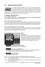
...motherboard drivers and the X.H.D utiltiy After installing the operating system, insert the motherboard driver disk. To manually set up a RAID 0 array. 2. 4-9 eXtreme Hard Drive (X.H.D) With GIGABYTE eXtreme Hard Drive (X.H.D)(Note 1), users can quickly configure a RAIDready system for RAID 0 when a new... depending on your hard drive read/write performance without the need for complex and time-consuming configurations. Unique Features Using GIGABYTE eXtreme Hard Drive (X.H.D) Instructions:(Note 2) Before launching X.H.D, make sure the new drive is added. Step 2: Install ...
...motherboard drivers and the X.H.D utiltiy After installing the operating system, insert the motherboard driver disk. To manually set up a RAID 0 array. 2. 4-9 eXtreme Hard Drive (X.H.D) With GIGABYTE eXtreme Hard Drive (X.H.D)(Note 1), users can quickly configure a RAIDready system for RAID 0 when a new... depending on your hard drive read/write performance without the need for complex and time-consuming configurations. Unique Features Using GIGABYTE eXtreme Hard Drive (X.H.D) Instructions:(Note 2) Before launching X.H.D, make sure the new drive is added. Step 2: Install ...
Manual
Page 86
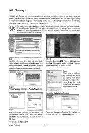
... existing Teaming, click the item you created, and then click the Remove button. Click Install under Realtek Ethernet Diagnostic Utility for GA-P55A-UD4P. Restart your network switch or router device manual for twice the transmission bandwidth, making data transmission more effective and also improving the quality of transmission of distant image(s). Teaming...
... existing Teaming, click the item you created, and then click the Remove button. Click Install under Realtek Ethernet Diagnostic Utility for GA-P55A-UD4P. Restart your network switch or router device manual for twice the transmission bandwidth, making data transmission more effective and also improving the quality of transmission of distant image(s). Teaming...

Manual
Page 93
... Select Disks Strip Size : N/A Capacity : 0.0 GB Sync : Continuous Create Volume [ HELP ] Select a sync option: On Request: volume is updated manually Continuous: volume is updated automatically [hi]-Change [TAB]-Next [ESC]-Previous Menu Figure 11 [ENTER]-Select Step 5: Finally press on the master drive will be... the data on the Create Volume item to begin creating the Recovery Volume and follow the onscreen instructions to the recovery drive manually using the Update Volume function of the Intel Matrix Storage Console in the system. Recovery: Copies data between a master and ...
... Select Disks Strip Size : N/A Capacity : 0.0 GB Sync : Continuous Create Volume [ HELP ] Select a sync option: On Request: volume is updated manually Continuous: volume is updated automatically [hi]-Change [TAB]-Next [ESC]-Previous Menu Figure 11 [ENTER]-Select Step 5: Finally press on the master drive will be... the data on the Create Volume item to begin creating the Recovery Volume and follow the onscreen instructions to the recovery drive manually using the Update Volume function of the Intel Matrix Storage Console in the system. Recovery: Copies data between a master and ...


