Manual
Page 1
GA-8I925X-G Intel® Pentium® 4 LGA775 Processor Motherboard User's Manual Rev. 2003 12ME-8I925XG-2003
GA-8I925X-G Intel® Pentium® 4 LGA775 Processor Motherboard User's Manual Rev. 2003 12ME-8I925XG-2003
Manual
Page 2
Motherboard GA-8I925X-G Jul. 2, 2004 Motherboard GA-8I925X-G Jul. 2, 2004
Motherboard GA-8I925X-G Jul. 2, 2004 Motherboard GA-8I925X-G Jul. 2, 2004
Manual
Page 4
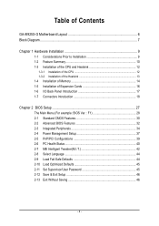
Table of Contents GA-8I925X-G Motherboard Layout 6 Block Diagram ...7 Chapter 1 Hardware Installation 9 1-1 Considerations Prior to Installation 9 1-2 Feature Summary 10 1-3 Installation of the CPU and Heatsink 12 1-3-1 Installation of the CPU ...
Table of Contents GA-8I925X-G Motherboard Layout 6 Block Diagram ...7 Chapter 1 Hardware Installation 9 1-1 Considerations Prior to Installation 9 1-2 Feature Summary 10 1-3 Installation of the CPU and Heatsink 12 1-3-1 Installation of the CPU ...
Manual
Page 6
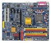
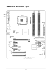
GA-8I925X-G Motherboard Layout DDRII1 DDRII2 DDRII4 DDRII5 KB_MS SPDIF_O SPDIF_I LGA775 GA-8I925X-G COM LPT USB USB LAN2 IT8712 AUDIO1 AUDIO2 ATX_12V CPU_FAN AZALIA_FP PCIE_16 Broadcom 5751 CODEC PCIE_1 PCIE_2 CD_IN PCIE_3 IR Main BIOS Backup BIOS Intel 925X PCI1 PCI2 F_USB1 PWR_FAN ATX IDE FDD SATA3_SB SATA2_SB Intel ICH6R SATA1_SB SATA0_SB BAT SYS_FAN F_PANEL PWR_LED F_USB2 CLR_CMOS - 6 -
GA-8I925X-G Motherboard Layout DDRII1 DDRII2 DDRII4 DDRII5 KB_MS SPDIF_O SPDIF_I LGA775 GA-8I925X-G COM LPT USB USB LAN2 IT8712 AUDIO1 AUDIO2 ATX_12V CPU_FAN AZALIA_FP PCIE_16 Broadcom 5751 CODEC PCIE_1 PCIE_2 CD_IN PCIE_3 IR Main BIOS Backup BIOS Intel 925X PCI1 PCI2 F_USB1 PWR_FAN ATX IDE FDD SATA3_SB SATA2_SB Intel ICH6R SATA1_SB SATA0_SB BAT SYS_FAN F_PANEL PWR_LED F_USB2 CLR_CMOS - 6 -
Manual
Page 10
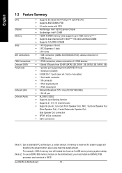
... (10/100/1000 Mbit) Š 1 RJ 45 port Š ALC880 CODEC Š Supports Jack Sensing function Š Supports 2 / 4 / 6 / 8 channel audio Š Supports Line In ; MIC ; GA-8I925X-G Motherboard - 10 - Center/Subwoofer Speaker Out ; For example, 4 GB of memory is reserved for system usage and therefore the actual memory size is less than...
... (10/100/1000 Mbit) Š 1 RJ 45 port Š ALC880 CODEC Š Supports Jack Sensing function Š Supports 2 / 4 / 6 / 8 channel audio Š Supports Line In ; MIC ; GA-8I925X-G Motherboard - 10 - Center/Subwoofer Speaker Out ; For example, 4 GB of memory is reserved for system usage and therefore the actual memory size is less than...
Manual
Page 12
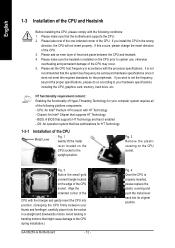
If you wish to set beyond the proper specifications, please do so according to the CPU during installation.) GA-8I925X-G Motherboard - 12 - Please add an even layer of heat sink paste between your thumb and forefinger, carefully place it does not meet the required standards ...
If you wish to set beyond the proper specifications, please do so according to the CPU during installation.) GA-8I925X-G Motherboard - 12 - Please add an even layer of heat sink paste between your thumb and forefinger, carefully place it does not meet the required standards ...
Manual
Page 14
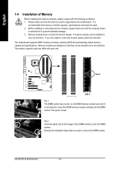
GA-8I925X-G Motherboard - 14 - It is switched off to remove the DIMM module. The motherboard supports DDR II memory modules, whereby BIOS will automatically detect memory capacity ...
GA-8I925X-G Motherboard - 14 - It is switched off to remove the DIMM module. The motherboard supports DDR II memory modules, whereby BIOS will automatically detect memory capacity ...
Manual
Page 15
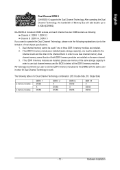
... Intel chipset specifications. 1. We'll strongly recommend our user to detect all the DDR II memory modules. Hardware Installation English Dual Channel DDR II GA-8I925X-G supports the Dual Channel Technology. Dual channel memory cannot be added to the Channel A slot and the other in the Channel B slot in ... memory and for BIOS to slot two DDR II memory modules into the DIMMs with the same color in order to use dual channel memory. GA-8I925X-G includes 4 DIMM sockets, and each Channel has two DIMM sockets as following: Channel A : DDR II 1, DDR II 2 Channel B : DDR II 4, DDR II 5 ...
... Intel chipset specifications. 1. We'll strongly recommend our user to detect all the DDR II memory modules. Hardware Installation English Dual Channel DDR II GA-8I925X-G supports the Dual Channel Technology. Dual channel memory cannot be added to the Channel A slot and the other in the Channel B slot in ... memory and for BIOS to slot two DDR II memory modules into the DIMMs with the same color in order to use dual channel memory. GA-8I925X-G includes 4 DIMM sockets, and each Channel has two DIMM sockets as following: Channel A : DDR II 1, DDR II 2 Channel B : DDR II 4, DDR II 5 ...
Manual
Page 16
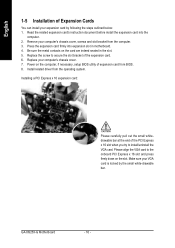
... x 16 slot and press firmly down on the card are indeed seated in motherboard. 4. Please align the VGA card to install/uninstall the VGA card. GA-8I925X-G Motherboard - 16 - Be sure the metal contacts on the slot. Replace the screw to secure the slot bracket of the expansion card. 6. English 1-5 Installation of...
... x 16 slot and press firmly down on the card are indeed seated in motherboard. 4. Please align the VGA card to install/uninstall the VGA card. GA-8I925X-G Motherboard - 16 - Be sure the metal contacts on the slot. Replace the screw to secure the slot bracket of the expansion card. 6. English 1-5 Installation of...
Manual
Page 18
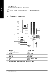
English Side Speaker Out Connect the side surround speakers to configure 2-/4-/6-/8-channel audio functioning. 1-7 Connectors Introduction 13 5 2 12 7 6 16 10 13 4 15 14 8 9 11 1) ATX_12V 9) PWR_LED 2) ATX (Power Connector) 10) BAT 3) CPU_FAN 11) F_PANEL 4) SYS_FAN 12) AZALIA_FP 5) PWR_FAN 13) CD_IN 6) FDD 14) F_USB1 / F_USB2 7) IDE 15) IR 8) SATA0_SB/SATA1_SB/SATA2_SB/SATA3_SB 16) CLR_CMOS GA-8I925X-G Motherboard - 18 - You can use audio software to this connector.
English Side Speaker Out Connect the side surround speakers to configure 2-/4-/6-/8-channel audio functioning. 1-7 Connectors Introduction 13 5 2 12 7 6 16 10 13 4 15 14 8 9 11 1) ATX_12V 9) PWR_LED 2) ATX (Power Connector) 10) BAT 3) CPU_FAN 11) F_PANEL 4) SYS_FAN 12) AZALIA_FP 5) PWR_FAN 13) CD_IN 6) FDD 14) F_USB1 / F_USB2 7) IDE 15) IR 8) SATA0_SB/SATA1_SB/SATA2_SB/SATA3_SB 16) CLR_CMOS GA-8I925X-G Motherboard - 18 - You can use audio software to this connector.
Manual
Page 20
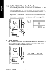
.... The types of the cable connects to prevent system overheating and failure. Please connect the red power connector wire to the pin1 position. 2 34 1 33 GA-8I925X-G Motherboard - 20 - Caution!
.... The types of the cable connects to prevent system overheating and failure. Please connect the red power connector wire to the pin1 position. 2 34 1 33 GA-8I925X-G Motherboard - 20 - Caution!
Manual
Page 22
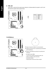
... OFF the computer and unplug the power cord. 2. Plug the power cord and turn ON the computer. - 22 - Definition 1 MPD+ 2 MPD- 1 3 MPD- 10) BAT(Battery) GA-8I925X-G Motherboard Danger of used batteries according to erase CMOS... 1. If you want to the manufacturer's instructions. It will blink when the system enters suspend mode...
... OFF the computer and unplug the power cord. 2. Plug the power cord and turn ON the computer. - 22 - Definition 1 MPD+ 2 MPD- 1 3 MPD- 10) BAT(Battery) GA-8I925X-G Motherboard Danger of used batteries according to erase CMOS... 1. If you want to the manufacturer's instructions. It will blink when the system enters suspend mode...
Manual
Page 24
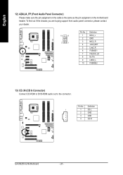
To find out if the chassis you are buying support front audio panel connector, please contact your dealer. 10 9 2 1 Pin No. 1 2 3 4 5 6 7 8 9 10 Definition MIC2_L GND MIC2_R -ACZ_DET Line2_R FSENSE1 FAUOIO_JD No Pin LINE2_L FSENSE2 13) CD_IN (CD In Connector) Connect CD-ROM or DVD-ROM audio out to the connector. Pin No. Definition 1 1 CD-L 2 GND 3 GND 4 CD-R GA-8I925X-G Motherboard - 24 - English 12) AZALIA_FP (Front Audio Panel Connector) Please make sure the pin assigment on the cable is the same as the pin assigment on the motherboard header.
To find out if the chassis you are buying support front audio panel connector, please contact your dealer. 10 9 2 1 Pin No. 1 2 3 4 5 6 7 8 9 10 Definition MIC2_L GND MIC2_R -ACZ_DET Line2_R FSENSE1 FAUOIO_JD No Pin LINE2_L FSENSE2 13) CD_IN (CD In Connector) Connect CD-ROM or DVD-ROM audio out to the connector. Pin No. Definition 1 1 CD-L 2 GND 3 GND 4 CD-R GA-8I925X-G Motherboard - 24 - English 12) AZALIA_FP (Front Audio Panel Connector) Please make sure the pin assigment on the cable is the same as the pin assigment on the motherboard header.
Manual
Page 26
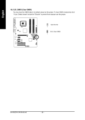
To clear CMOS, temporarily short 1-2 pin. Open: Normal 1 Short: Clear CMOS 1 GA-8I925X-G Motherboard - 26 - English 16) CLR_CMOS (Clear CMOS) You may clear the CMOS data to prevent from improper use this jumper. Default doesn't include the "Shunter" to its default values by this jumper.
To clear CMOS, temporarily short 1-2 pin. Open: Normal 1 Short: Clear CMOS 1 GA-8I925X-G Motherboard - 26 - English 16) CLR_CMOS (Clear CMOS) You may clear the CMOS data to prevent from improper use this jumper. Default doesn't include the "Shunter" to its default values by this jumper.
Manual
Page 28
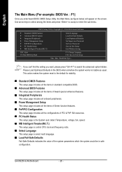
... multi language. „ Load Fail-Safe Defaults Fail-Safe Defaults indicates the value of the system parameters which the system would be in safe configuration. GA-8I925X-G Motherboard - 28 - If you can't find the setting you enter Award BIOS CMOS Setup Utility, the Main Menu (as usual. Please Load Optimized Defaults in...
... multi language. „ Load Fail-Safe Defaults Fail-Safe Defaults indicates the value of the system parameters which the system would be in safe configuration. GA-8I925X-G Motherboard - 28 - If you can't find the setting you enter Award BIOS CMOS Setup Utility, the Main Menu (as usual. Please Load Optimized Defaults in...
Manual
Page 30
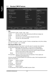
... 0 Master/Slave IDE Device Setup. Through Dec. Manual User can use one of sectors If a hard disk has not been installed, select NONE and press . GA-8I925X-G Motherboard - 30 - time clock. The four options are used and the system will skip the automatic detection step and allow for automatic device detection. Jan...
... 0 Master/Slave IDE Device Setup. Through Dec. Manual User can use one of sectors If a hard disk has not been installed, select NONE and press . GA-8I925X-G Motherboard - 30 - time clock. The four options are used and the system will skip the automatic detection step and allow for automatic device detection. Jan...

Manual
Page 32
.... Hard Disk Boot Priority Select boot sequence for onboard(or add-on cards) SCSI, RAID, etc. Hard Disk Select your boot device priority by ZIP. GA-8I925X-G Motherboard - 32 - English 2-2 Advanced BIOS Features CMOS Setup Utility-Copyright (C) 1984-2004 Award Software Advanced BIOS Features ` Hard Disk Boot Priority First Boot Device Second...
.... Hard Disk Boot Priority Select boot sequence for onboard(or add-on cards) SCSI, RAID, etc. Hard Disk Select your boot device priority by ZIP. GA-8I925X-G Motherboard - 32 - English 2-2 Advanced BIOS Features CMOS Setup Utility-Copyright (C) 1984-2004 Award Software Advanced BIOS Features ` Hard Disk Boot Priority First Boot Device Second...
Manual
Page 34
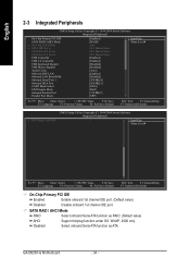
... Seria ATA function as RAID. (Default value) AHCI Support hotplug function under OS. SATA RAID / AHCI Mode RAID Select onboard Seria ATA function as ATA. GA-8I925X-G Motherboard - 34 - English 2-3 Integrated Peripherals CMOS Setup Utility-Copyright (C) 1984-2004 Award Software Integrated Peripherals On-Chip Primary PCI IDE SATA RAID/AHCI Mode x On...
... Seria ATA function as RAID. (Default value) AHCI Support hotplug function under OS. SATA RAID / AHCI Mode RAID Select onboard Seria ATA function as ATA. GA-8I925X-G Motherboard - 34 - English 2-3 Integrated Peripherals CMOS Setup Utility-Copyright (C) 1984-2004 Award Software Integrated Peripherals On-Chip Primary PCI IDE SATA RAID/AHCI Mode x On...
Manual
Page 36
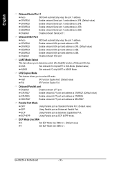
... address is 3F8. (Default value) Enable onboard Serial port 1 and address is 2F8. 3E8/IRQ4 2E8/IRQ3 Enable onboard Serial port 1 and address is 3E8. GA-8I925X-G Motherboard - 36 - English Onboard Serial Port 1 Auto BIOS will automatically setup the port 1 address. 3F8/IRQ4 2F8/IRQ3 Enable onboard IrDA port and address is...
... address is 3F8. (Default value) Enable onboard Serial port 1 and address is 2F8. 3E8/IRQ4 2E8/IRQ3 Enable onboard Serial port 1 and address is 3E8. GA-8I925X-G Motherboard - 36 - English Onboard Serial Port 1 Auto BIOS will automatically setup the port 1 address. 3F8/IRQ4 2F8/IRQ3 Enable onboard IrDA port and address is...
Manual
Page 38
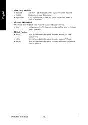
.... KB Power ON Password When "Power On by Keyboard Password Enter from 1 to 5 characters) and press Enter to the Last state before AC-power off. GA-8I925X-G Motherboard - 38 - Disabled Disabled this function. (Default value) Keyboard 98 If your keyboard have "POWER Key" button, you can press the key to the system...
.... KB Power ON Password When "Power On by Keyboard Password Enter from 1 to 5 characters) and press Enter to the Last state before AC-power off. GA-8I925X-G Motherboard - 38 - Disabled Disabled this function. (Default value) Keyboard 98 If your keyboard have "POWER Key" button, you can press the key to the system...

