
Manual
Page 4
... Layout 6 Block Diagram ...7 Chapter 1 Hardware Installation 9 1-1 Considerations Prior to Installation 9 1-2 Feature Summary 10 1-3 Installation of the CPU and Heatsink 12 1-3-1 Installation of the CPU 12 1-3-2 Installation of the Heatsink 13 1-4 Installing/Removing Cool-Plus (Northbridge Cooling Fan 14 1-5 Installation of Memory 14 1-6 Installation of Expansion Cards 16 1-7 Configuring a Quad View System 17 1-8 Installation of U-Plus DPS (Universal Plus Dual Power System 19 1-9 I/O Back Panel Introduction 20 1-10 Connectors Introduction 21 Chapter 2 BIOS Setup 31 The Main Menu...
... Layout 6 Block Diagram ...7 Chapter 1 Hardware Installation 9 1-1 Considerations Prior to Installation 9 1-2 Feature Summary 10 1-3 Installation of the CPU and Heatsink 12 1-3-1 Installation of the CPU 12 1-3-2 Installation of the Heatsink 13 1-4 Installing/Removing Cool-Plus (Northbridge Cooling Fan 14 1-5 Installation of Memory 14 1-6 Installation of Expansion Cards 16 1-7 Configuring a Quad View System 17 1-8 Installation of U-Plus DPS (Universal Plus Dual Power System 19 1-9 I/O Back Panel Introduction 20 1-10 Connectors Introduction 21 Chapter 2 BIOS Setup 31 The Main Menu...
Manual
Page 11
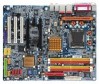
...Line Out (Front Speaker Out) ; English Onboard Audio Š ALC880 CODEC Š Supports Jack Sensing function Š Supports 2 / 4 / 6 / 8 channel audio Š Supports Line In ; Side Speaker Out connection Š SPDIF In/Out connection Š CD In connection I/O Control Š IT8712 Hardware Monitor Š System voltage detection Š CPU temperature detection Š CPU / System / Power fan speed detection Š CPU warning temperature Š CPU / System / Power fan failure warning Š CPU smart fan control Onboard SATA RAID Š Onboard ICH6R chipset (SATA0_SB...
...Line Out (Front Speaker Out) ; English Onboard Audio Š ALC880 CODEC Š Supports Jack Sensing function Š Supports 2 / 4 / 6 / 8 channel audio Š Supports Line In ; Side Speaker Out connection Š SPDIF In/Out connection Š CD In connection I/O Control Š IT8712 Hardware Monitor Š System voltage detection Š CPU temperature detection Š CPU / System / Power fan speed detection Š CPU warning temperature Š CPU / System / Power fan failure warning Š CPU smart fan control Onboard SATA RAID Š Onboard ICH6R chipset (SATA0_SB...

Manual
Page 14
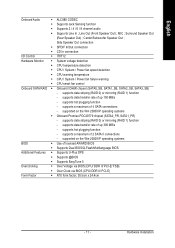
Firmly press down until it snaps into the NB_FAN connector. Fig.2 Once the fan is supported by the motherboard. If you are designed so that the memory used is properly affixed onto the heatsink, plug the power cable into position. The memory capacity used . 2. English 1-4 Installing/Removing Cool-Plus (Northbridge Cooling Fan) Fig.1 To attach Cool-Plus to a heatsink, align the extensions on both sides with the...
Firmly press down until it snaps into the NB_FAN connector. Fig.2 Once the fan is supported by the motherboard. If you are designed so that the memory used is properly affixed onto the heatsink, plug the power cable into position. The memory capacity used . 2. English 1-4 Installing/Removing Cool-Plus (Northbridge Cooling Fan) Fig.1 To attach Cool-Plus to a heatsink, align the extensions on both sides with the...

Manual
Page 15
... GA-8AENXP Dual Graphic includes 4 DIMM sockets, and each Channel has 2 DIMM sockets as following is activated, the bandwidth of the DIMM sockets to remove the DIMM module. If four DDR II memory modules are installed on the same channel. 3. Fig.2 Close the plastic clip at both DDR II memory modules are installed, please use memory of the same storage capacity in order to use dual channel memory. When the Dual Channel Technology is a Dual Channel Memory configuration...
... GA-8AENXP Dual Graphic includes 4 DIMM sockets, and each Channel has 2 DIMM sockets as following is activated, the bandwidth of the DIMM sockets to remove the DIMM module. If four DDR II memory modules are installed on the same channel. 3. Fig.2 Close the plastic clip at both DDR II memory modules are installed, please use memory of the same storage capacity in order to use dual channel memory. When the Dual Channel Technology is a Dual Channel Memory configuration...
Manual
Page 16
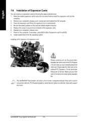
... computer, if necessary, setup BIOS utility of expansion card from BIOS. 8. Power on the card are based on the slot. GA-8AENXP Dual Graphic Motherboard - 16 - Installing a PCI Express x 16 expansion card: Please carefully pull out the small whitedrawable bar at the end of the expansion card. 6. Replace your computer's chassis cover. 7. Please align the VGA card to install/uninstall the VGA card. The GA-8AENXP Dual Graphic will allow a four-monitor configuration(Quad View) when used in motherboard. 4. Install related driver from the computer...
... computer, if necessary, setup BIOS utility of expansion card from BIOS. 8. Power on the card are based on the slot. GA-8AENXP Dual Graphic Motherboard - 16 - Installing a PCI Express x 16 expansion card: Please carefully pull out the small whitedrawable bar at the end of the expansion card. 6. Replace your computer's chassis cover. 7. Please align the VGA card to install/uninstall the VGA card. The GA-8AENXP Dual Graphic will allow a four-monitor configuration(Quad View) when used in motherboard. 4. Install related driver from the computer...
Manual
Page 18
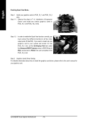
... BIOS Setup to PEG; set the Init Display First item under the Advanced BIOS Features menu in the PCIE_16_1 slot, set this item to PCIE_16_1 and PCIE_16_2 slots. If you must connect four different monitors to PCIE_16_1 and PCIE_16_2 slots. GA-8AENXP Dual Graphic Motherboard - 18 - Step 2: Graphics Cards Driver Setting For detailed information about how to install the graphics card driver, please refer to the user's manual for your graphics cards to all four video output ports (D-Sub/DVI). Step 1: Install...
... BIOS Setup to PEG; set the Init Display First item under the Advanced BIOS Features menu in the PCIE_16_1 slot, set this item to PCIE_16_1 and PCIE_16_2 slots. If you must connect four different monitors to PCIE_16_1 and PCIE_16_2 slots. GA-8AENXP Dual Graphic Motherboard - 18 - Step 2: Graphics Cards Driver Setting For detailed information about how to install the graphics card driver, please refer to the user's manual for your graphics cards to all four video output ports (D-Sub/DVI). Step 1: Install...
Manual
Page 34
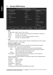
... option based on this option for the hard drive. English 2-1 Standard CMOS Features Date (mm:dd:yy) Time (hh:mm:ss) CMOS Setup Utility-Copyright (C) 1984-2005 Award Software Standard CMOS Features Tue, Jan 25 2005 22:31:24 Item Help Menu Level` ` IDE Channel 0 Master ` IDE Channel 0 Slave [None] [None] Change the day, month, year Drive A Drive B Floppy 3 Mode Suport Halt On [1.44M, 3.5"] [None] [Disabled] [All, But Keyboard] Sun. to Dec. time clock. GA-8AENXP Dual Graphic Motherboard...
... option based on this option for the hard drive. English 2-1 Standard CMOS Features Date (mm:dd:yy) Time (hh:mm:ss) CMOS Setup Utility-Copyright (C) 1984-2005 Award Software Standard CMOS Features Tue, Jan 25 2005 22:31:24 Item Help Menu Level` ` IDE Channel 0 Master ` IDE Channel 0 Slave [None] [None] Change the day, month, year Drive A Drive B Floppy 3 Mode Suport Halt On [1.44M, 3.5"] [None] [Disabled] [All, But Keyboard] Sun. to Dec. time clock. GA-8AENXP Dual Graphic Motherboard...
Manual
Page 37
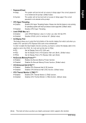
...) Enabled Disabled Enables No-Execute Memory Protect function. BIOS Setup In order to enable the Dual Graphic function correctly, you have to connect the display cable to the graphics card in the PCIE_16_2 slot and set this feature is only working for windows XP. (Default value) Init Display First This feature allows you install a PCI card and a PCI Express VGA card on the motherboard. PEG Set Init Display First to PCI Express VGA card (Slot1). (Default value) PEG2 Set Init Display First to PCI VGA card. Disables CPU Thermal Monitor 2 (TM2) function. (Default value...
...) Enabled Disabled Enables No-Execute Memory Protect function. BIOS Setup In order to enable the Dual Graphic function correctly, you have to connect the display cable to the graphics card in the PCIE_16_2 slot and set this feature is only working for windows XP. (Default value) Init Display First This feature allows you install a PCI card and a PCI Express VGA card on the motherboard. PEG Set Init Display First to PCI Express VGA card (Slot1). (Default value) PEG2 Set Init Display First to PCI VGA card. Disables CPU Thermal Monitor 2 (TM2) function. (Default value...

Manual
Page 47
...x 2. 2.66 Memory Frequency = Host clock x 2.66. 3.00(Note) Memory Frequency = Host clock x 3. PCI-E OverVoltage Control Normal Set PCI-E OverVoltage Control to 2.66. - 47 - Auto Set Memory frequency by DRAM SPD data. (Default value) Memory Frequency (Mhz) The values depend on the motherboard, you use an 800Mhz FSB processor, please set Memory Frequency For to Normal. (Default value) +0.1V ~ +0.3V Increase voltage range as user selected. BIOS Setup If you use a 533Mhz FSB processor, please set Memory Frequency For to 130Mhz. CPU Voltage Control Supports...
...x 2. 2.66 Memory Frequency = Host clock x 2.66. 3.00(Note) Memory Frequency = Host clock x 3. PCI-E OverVoltage Control Normal Set PCI-E OverVoltage Control to 2.66. - 47 - Auto Set Memory frequency by DRAM SPD data. (Default value) Memory Frequency (Mhz) The values depend on the motherboard, you use an 800Mhz FSB processor, please set Memory Frequency For to Normal. (Default value) +0.1V ~ +0.3V Increase voltage range as user selected. BIOS Setup If you use a 533Mhz FSB processor, please set Memory Frequency For to 130Mhz. CPU Voltage Control Supports...
Manual
Page 49
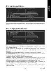
... F8: Dual BIOS/Q-Flash F3: Change Language F10: Save & Exit Setup Load Optimized Defaults Selecting this function, the following message will appear at "Password Check" in Advance BIOS Features Menu, you will boot and you to specify two separate passwords: SUPERVISOR PASSWORD and a USER PASSWORD. English 2-10 Load Optimized Defaults CMOS Setup Utility-Copyright (C) 1984-2005 Award Software ` Standard CMOS Features Select Language ` Advanced BIOS Features Load Fail-Safe Defaults ` Integrated Peripherals Load Optimized Defaults ` Power Management Setup Set Supervisor Password...
... F8: Dual BIOS/Q-Flash F3: Change Language F10: Save & Exit Setup Load Optimized Defaults Selecting this function, the following message will appear at "Password Check" in Advance BIOS Features Menu, you will boot and you to specify two separate passwords: SUPERVISOR PASSWORD and a USER PASSWORD. English 2-10 Load Optimized Defaults CMOS Setup Utility-Copyright (C) 1984-2005 Award Software ` Standard CMOS Features Select Language ` Advanced BIOS Features Load Fail-Safe Defaults ` Integrated Peripherals Load Optimized Defaults ` Power Management Setup Set Supervisor Password...
Manual
Page 54
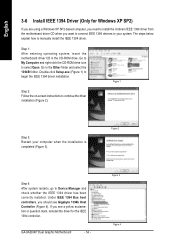
Step 1: After entering operating system, insert the motherboard driver CD in the CD-ROM drive. English 3-6 Install IEEE 1394 Driver (Only for the IEEE 1394 controller. Go to select Open. Under IEEE 1394 Bus host controllers, you want to connect IEEE 1394 devices to install the Unibrain IEEE 1394 driver from the motherboard driver CD when you should see Gigabyte 1394b Host Controller (Figure 4). GA-8AENXP Dual Graphic Motherboard - 54 - Go to My Computer...
Step 1: After entering operating system, insert the motherboard driver CD in the CD-ROM drive. English 3-6 Install IEEE 1394 Driver (Only for the IEEE 1394 controller. Go to select Open. Under IEEE 1394 Bus host controllers, you want to connect IEEE 1394 devices to install the Unibrain IEEE 1394 driver from the motherboard driver CD when you should see Gigabyte 1394b Host Controller (Figure 4). GA-8AENXP Dual Graphic Motherboard - 54 - Go to My Computer...

Manual
Page 56
... driver has been changed correctly. GA-8AENXP Dual Graphic Motherboard - 56 - When it's done, remember to go back to Device Manager to install and click Next (Figure 12). Step 2: Right-click Gigabyte 1394b Host Controller and select Update Driver (Figure 10). Figure 9 Step 3: When the Hardware Update Wizard appears, select Install from Device Manager Step 1: Access Device Manager through Control Panel\System\Hardware and you should see Gigabyte IEEE 1394b Host Controller...
... driver has been changed correctly. GA-8AENXP Dual Graphic Motherboard - 56 - When it's done, remember to go back to Device Manager to install and click Next (Figure 12). Step 2: Right-click Gigabyte 1394b Host Controller and select Update Driver (Figure 10). Figure 9 Step 3: When the Hardware Update Wizard appears, select Install from Device Manager Step 1: Access Device Manager through Control Panel\System\Hardware and you should see Gigabyte IEEE 1394b Host Controller...
Manual
Page 57
... original M.I.B., the new Memory Intelligent Booster 2 (M.I .A. 2) is designed to automatically adjust CPU computing power to change BIOS feature settings with the latest LGA775 Intel® Pentium® 4 Processor as well as providing the most up the PC chassis and short-circuit the "Clear CMOS" pins or the battery on the U-Plus D.P.S. feature, users no longer required to switch into different modes within BIOS setup in order to maximize...
... original M.I.B., the new Memory Intelligent Booster 2 (M.I .A. 2) is designed to automatically adjust CPU computing power to change BIOS feature settings with the latest LGA775 Intel® Pentium® 4 Processor as well as providing the most up the PC chassis and short-circuit the "Clear CMOS" pins or the battery on the U-Plus D.P.S. feature, users no longer required to switch into different modes within BIOS setup in order to maximize...

Manual
Page 58
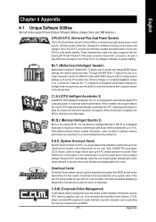
... page Enters the PC Health setting page Confirmation and Execution button Toggles between Easy and Advance Mode Display panel of both CPU cooling fan and North-Bridge Chipset cooling fan, 4) PC health for enhancing system performance, 2) C.I .B.2 3. C.I.A./C.I.A.2 and M.I.B./M.I .A. Smart-Fan 4. GO 6. GIGABYTE Logo 10. English 4-1-1 EasyTune 5 Introduction EasyTune 5 presents the most convenient Windows based system performance enhancement and manageability utility. Function display LEDs 9. GA-8AENXP Dual Graphic Motherboard - 58 - Featuring several powerful yet...
... page Enters the PC Health setting page Confirmation and Execution button Toggles between Easy and Advance Mode Display panel of both CPU cooling fan and North-Bridge Chipset cooling fan, 4) PC health for enhancing system performance, 2) C.I .B.2 3. C.I.A./C.I.A.2 and M.I.B./M.I .A. Smart-Fan 4. GO 6. GIGABYTE Logo 10. English 4-1-1 EasyTune 5 Introduction EasyTune 5 presents the most convenient Windows based system performance enhancement and manageability utility. Function display LEDs 9. GA-8AENXP Dual Graphic Motherboard - 58 - Featuring several powerful yet...
Manual
Page 62
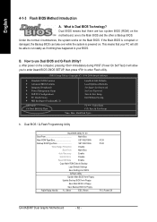
... Main Bios Auto Recovery Enable Halt On Error Disable Keep DMI Data Enable Copy Main ROM Data to Backup Load Default Settings Save Settings to CMOS Q-Flash Utility Update Main BIOS from Floppy Update Backup BIOS from Floppy Save Main BIOS to Floppy Save Backup BIOS to enter Flash utility. b. English 4-1-3 Flash BIOS Method Introduction A. B. How to run stably as if nothing has happened in your PC will allow you to enter Award BIOS CMOS SETUP, then press to Floppy PgDn/PgUp: Modify : Move ESC: Reset 512K 512K F10: Power Off GA-8AENXP Dual Graphic Motherboard...
... Main Bios Auto Recovery Enable Halt On Error Disable Keep DMI Data Enable Copy Main ROM Data to Backup Load Default Settings Save Settings to CMOS Q-Flash Utility Update Main BIOS from Floppy Update Backup BIOS from Floppy Save Main BIOS to Floppy Save Backup BIOS to enter Flash utility. b. English 4-1-3 Flash BIOS Method Introduction A. B. How to run stably as if nothing has happened in your PC will allow you to enter Award BIOS CMOS SETUP, then press to Floppy PgDn/PgUp: Modify : Move ESC: Reset 512K 512K F10: Power Off GA-8AENXP Dual Graphic Motherboard...

Manual
Page 65
...: Dual BIOS/Q-Flash Select Language Load Fail-Safe Defaults Load Optimized Defaults Set Supervisor Password Set User Password Save & Exit Setup Exit Without Saving F3: Change Language F10: Save & Exit Setup Time, Date, Hard Disk Type... Blocking a task and pressing Enter key on your keyboard to enable execution of the task. Action bar: Contains the names of eight tasks and two item showing information about the BIOS ROM type. Task menu for Dual BIOS utility Task menu for Q-FlashTM utility Dual BIOS Utility Boot From Main Bios Main ROM Type/Size SST...
...: Dual BIOS/Q-Flash Select Language Load Fail-Safe Defaults Load Optimized Defaults Set Supervisor Password Set User Password Save & Exit Setup Exit Without Saving F3: Change Language F10: Save & Exit Setup Time, Date, Hard Disk Type... Blocking a task and pressing Enter key on your keyboard to enable execution of the task. Action bar: Contains the names of eight tasks and two item showing information about the BIOS ROM type. Task menu for Dual BIOS utility Task menu for Q-FlashTM utility Dual BIOS Utility Boot From Main Bios Main ROM Type/Size SST...
Manual
Page 67
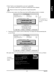
...On Error Disable CPolpeyasMe apirneRssOaMnyDkaetya to Bcoancktiunpue Load Default Settings Save Settings to CMOS Q-Flash Utility Load Main BIOS from Floppy Load Backup BIOS from Floppy Save Main BIOS to Floppy Save Backup BIOS to Floppy Enter : Run :Move ESC:Reset F10:Power Off After system reboots, you may find the BIOS version on your boot screen becomes the one you flashed. Halt On Error Disable [EnCtoepr]y tMo acionnRtiOnuMreDoarta[EtoscB]atcokuapbort... Then it begins flashing BIOS. 4. Appendix Press Esc and then Y button to enter SETUP / Dual BIOS / Q-Flash / F9...
...On Error Disable CPolpeyasMe apirneRssOaMnyDkaetya to Bcoancktiunpue Load Default Settings Save Settings to CMOS Q-Flash Utility Load Main BIOS from Floppy Load Backup BIOS from Floppy Save Main BIOS to Floppy Save Backup BIOS to Floppy Enter : Run :Move ESC:Reset F10:Power Off After system reboots, you may find the BIOS version on your boot screen becomes the one you flashed. Halt On Error Disable [EnCtoepr]y tMo acionnRtiOnuMreDoarta[EtoscB]atcokuapbort... Then it begins flashing BIOS. 4. Appendix Press Esc and then Y button to enter SETUP / Dual BIOS / Q-Flash / F9...
Manual
Page 74
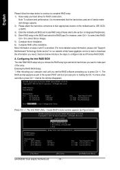
... Accelerator RAID Option ROM v4.0.6180 Copyright(C) 2003-04 Intel Corporation. Exit RAID Volumes : None Defined. [ DISK/VOLUME INFORMATION ] Physical Disks : Port Driver Model 0 ST3120026AS 1 ST3120026AS Serial # 3JT354CP 3JT329JX Size Type/Status(Vol ID) 111.7GB Non-RAID Disk 111.7GB Non-RAID Disk [ ]-Select GA-8AENXP Dual Graphic Motherboard [ESC]-Exit - 74 - [ENTER]-Select Menu More information on steps 4 and 5 is recommended that the hard drives used are of the array. IDE, SCSI, or SATA. 3) Enter the motherboard BIOS and locate RAID setup...
... Accelerator RAID Option ROM v4.0.6180 Copyright(C) 2003-04 Intel Corporation. Exit RAID Volumes : None Defined. [ DISK/VOLUME INFORMATION ] Physical Disks : Port Driver Model 0 ST3120026AS 1 ST3120026AS Serial # 3JT354CP 3JT329JX Size Type/Status(Vol ID) 111.7GB Non-RAID Disk 111.7GB Non-RAID Disk [ ]-Select GA-8AENXP Dual Graphic Motherboard [ESC]-Exit - 74 - [ENTER]-Select Menu More information on steps 4 and 5 is recommended that the hard drives used are of the array. IDE, SCSI, or SATA. 3) Enter the motherboard BIOS and locate RAID setup...
Manual
Page 84
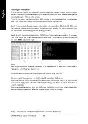
... transfer this floppy disk. Without the driver, the hard disk may not be installed.) (Note) In the menu list, Intel Application Accelerator 4.0 is Intel ICH6R chipset. The installation utility will appear automatically soon after you complete the steps, boot from the Windows CD to a floppy disk. Follow on-screen instructions to complete installation. (Each time you have to copy the driver for the SATA controller on your motherboard from HDDs in the driver CD...
... transfer this floppy disk. Without the driver, the hard disk may not be installed.) (Note) In the menu list, Intel Application Accelerator 4.0 is Intel ICH6R chipset. The installation utility will appear automatically soon after you complete the steps, boot from the Windows CD to a floppy disk. Follow on-screen instructions to complete installation. (Each time you have to copy the driver for the SATA controller on your motherboard from HDDs in the driver CD...
Manual
Page 90
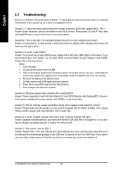
... battery holder to makethem short for one minute). 4. Answer: If your own cable, please remove it . Question 5: Why do not connect any of your board doesn't have connected any setting manually to disable the onboard VGA. If not, please change any cable that were included in previous BIOS after updating BIOS. Connect power cord to load Fail-Safe Defaults (Or Load BIOS Defaults) after flashing BIOS. To check general asked questions. Turn off the on-board battery to leak voltage to clear CMOS...
... battery holder to makethem short for one minute). 4. Answer: If your own cable, please remove it . Question 5: Why do not connect any of your board doesn't have connected any setting manually to disable the onboard VGA. If not, please change any cable that were included in previous BIOS after updating BIOS. Connect power cord to load Fail-Safe Defaults (Or Load BIOS Defaults) after flashing BIOS. To check general asked questions. Turn off the on-board battery to leak voltage to clear CMOS...


