Manual
Page 1
GA-8AENXP Dual Graphic Intel® Pentium® 4 LGA775 Processor Motherboard User's Manual Rev. 1001 12ME-8AENXPDG-1001
GA-8AENXP Dual Graphic Intel® Pentium® 4 LGA775 Processor Motherboard User's Manual Rev. 1001 12ME-8AENXPDG-1001
Manual
Page 2
Motherboard GA-8AENXP Dual Graphic Feb. 4, 2005 Motherboard GA-8AENXP Dual Graphic Feb. 4, 2005
Motherboard GA-8AENXP Dual Graphic Feb. 4, 2005 Motherboard GA-8AENXP Dual Graphic Feb. 4, 2005

Manual
Page 4
Table of Contents GA-8AENXP Dual Graphic Motherboard Layout 6 Block Diagram ...7 Chapter 1 Hardware Installation 9 1-1 Considerations Prior to Installation 9 1-2 Feature Summary 10 1-3 Installation of the CPU and Heatsink 12 1-3-1 Installation ...(Northbridge Cooling Fan 14 1-5 Installation of Memory 14 1-6 Installation of Expansion Cards 16 1-7 Configuring a Quad View System 17 1-8 Installation of U-Plus DPS (Universal Plus Dual Power System 19 1-9 I/O Back Panel Introduction 20 1-10 Connectors Introduction 21 Chapter 2 BIOS Setup 31 The Main Menu (For example: BIOS Ver. : E15 32 ...
Table of Contents GA-8AENXP Dual Graphic Motherboard Layout 6 Block Diagram ...7 Chapter 1 Hardware Installation 9 1-1 Considerations Prior to Installation 9 1-2 Feature Summary 10 1-3 Installation of the CPU and Heatsink 12 1-3-1 Installation ...(Northbridge Cooling Fan 14 1-5 Installation of Memory 14 1-6 Installation of Expansion Cards 16 1-7 Configuring a Quad View System 17 1-8 Installation of U-Plus DPS (Universal Plus Dual Power System 19 1-9 I/O Back Panel Introduction 20 1-10 Connectors Introduction 21 Chapter 2 BIOS Setup 31 The Main Menu (For example: BIOS Ver. : E15 32 ...

Manual
Page 10
...; Northbridge: Intel® 925XE Express Chipset Š Southbridge: Intel® ICH6R Š 4 DDR II DIMM memory slots (supports up to 4GB memory) (Note 1) Š Supports dual channel DDR II 711/600(Note 2)/533/400 unbrffered DIMM Š Supports 1.8V DDR II DIMM Š 2 PCI Express x 16 slots Š 1 PCI Express x 1 slot... 3.xxGB memory during system startup. (Note 2) To use a DDRII 600 memory module on the motherboard, you must install a 1066MHz FSB processor and overclock in BIOS. GA-8AENXP Dual Graphic Motherboard - 10 -
...; Northbridge: Intel® 925XE Express Chipset Š Southbridge: Intel® ICH6R Š 4 DDR II DIMM memory slots (supports up to 4GB memory) (Note 1) Š Supports dual channel DDR II 711/600(Note 2)/533/400 unbrffered DIMM Š Supports 1.8V DDR II DIMM Š 2 PCI Express x 16 slots Š 1 PCI Express x 1 slot... 3.xxGB memory during system startup. (Note 2) To use a DDRII 600 memory module on the motherboard, you must install a 1066MHz FSB processor and overclock in BIOS. GA-8AENXP Dual Graphic Motherboard - 10 -
Manual
Page 12
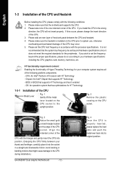
...please change the insert direction of the CPU. Fig. 2 Remove the plastic covering on the CPU prior to the CPU during installation.) GA-8AENXP Dual Graphic Motherboard - 12 - Fig. 4 Once the CPU is properly inserted, please replace the load plate and push the metal lever back... downwards motion. HT functionality requirement content : Enabling the functionality of Hyper-Threading Technology for your hardware specifications including the CPU, graphics card, memory, hard drive, etc. Align the indented corner of the CPU with the processor specifications. Please make sure that...
...please change the insert direction of the CPU. Fig. 2 Remove the plastic covering on the CPU prior to the CPU during installation.) GA-8AENXP Dual Graphic Motherboard - 12 - Fig. 4 Once the CPU is properly inserted, please replace the load plate and push the metal lever back... downwards motion. HT functionality requirement content : Enabling the functionality of Hyper-Threading Technology for your hardware specifications including the CPU, graphics card, memory, hard drive, etc. Align the indented corner of the CPU with the processor specifications. Please make sure that...

Manual
Page 14
... removal might cause the side extensions to break-off to prevent hardware damage. 3. Memory modules are unable to insert the module, please switch the direction. GA-8AENXP Dual Graphic Motherboard - 14 - A memory module can be inserted only in the heatsink as shown. English 1-4 Installing/Removing Cool-Plus (Northbridge Cooling Fan) Fig.1 To attach Cool...
... removal might cause the side extensions to break-off to prevent hardware damage. 3. Memory modules are unable to insert the module, please switch the direction. GA-8AENXP Dual Graphic Motherboard - 14 - A memory module can be inserted only in the heatsink as shown. English 1-4 Installing/Removing Cool-Plus (Northbridge Cooling Fan) Fig.1 To attach Cool...

Manual
Page 15
... II Memory Configuration The GA-8AENXP Dual Graphic supports the Dual Channel Technology. Dual channel memory cannot function if both edges of ...II memory modules are installed, please use memory of the same storage capacity in order to operate the Dual Channel Technology, please follow the guidelines below for BIOS to remove the DIMM module. Then push it...the plastic clip at both DDR II memory modules are installed on the same channel. 3. The GA-8AENXP Dual Graphic includes 4 DIMM sockets, and each Channel has 2 DIMM sockets as following is activated, the bandwidth of the...
... II Memory Configuration The GA-8AENXP Dual Graphic supports the Dual Channel Technology. Dual channel memory cannot function if both edges of ...II memory modules are installed, please use memory of the same storage capacity in order to operate the Dual Channel Technology, please follow the guidelines below for BIOS to remove the DIMM module. Then push it...the plastic clip at both DDR II memory modules are installed on the same channel. 3. The GA-8AENXP Dual Graphic includes 4 DIMM sockets, and each Channel has 2 DIMM sockets as following is activated, the bandwidth of the...
Manual
Page 16
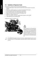
... the expansion card. 6. Make sure your VGA card is locked by following the steps outlined below: 1. The GA-8AENXP Dual Graphic will allow a four-monitor configuration(Quad View) when used in conjunction with two PCI Express graphics cards that are indeed seated in motherboard. 4. Be sure the metal contacts on the card are based on... BIOS. 8. Replace your computer's chassis cover, screws and slot bracket from the operating system. Remove your computer's chassis cover. 7. Install related driver from the computer. 3. GA-8AENXP Dual Graphic Motherboard - 16 -
... the expansion card. 6. Make sure your VGA card is locked by following the steps outlined below: 1. The GA-8AENXP Dual Graphic will allow a four-monitor configuration(Quad View) when used in conjunction with two PCI Express graphics cards that are indeed seated in motherboard. 4. Be sure the metal contacts on the card are based on... BIOS. 8. Replace your computer's chassis cover, screws and slot bracket from the operating system. Remove your computer's chassis cover. 7. Install related driver from the computer. 3. GA-8AENXP Dual Graphic Motherboard - 16 -
Manual
Page 18
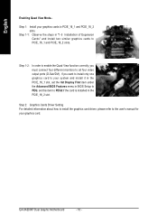
...BIOS Features menu in BIOS Setup to all four video output ports (D-Sub/DVI). GA-8AENXP Dual Graphic Motherboard - 18 - Step 1-2: In order to enable the Quad View function correctly, you want to install only one graphics card to your system and install it in the PCIE_16_1 slot, set this item ...to PEG2 if the card is installed in "1-5 Installation of Expansion Cards" and install two similar graphics cards to PCIE_16_1 and PCIE_16_2 slots. Step 1-1: Observe the steps in the PCIE_16_2 slot. English Enabling Quad View Mode-- Step 1: Install your...
...BIOS Features menu in BIOS Setup to all four video output ports (D-Sub/DVI). GA-8AENXP Dual Graphic Motherboard - 18 - Step 1-2: In order to enable the Quad View function correctly, you want to install only one graphics card to your system and install it in the PCIE_16_1 slot, set this item ...to PEG2 if the card is installed in "1-5 Installation of Expansion Cards" and install two similar graphics cards to PCIE_16_1 and PCIE_16_2 slots. Step 1-1: Observe the steps in the PCIE_16_2 slot. English Enabling Quad View Mode-- Step 1: Install your...

Manual
Page 20
... connector. If your OS supports USB controller. Line Out (Front Speaker Out) Connect the stereo speakers, earphone or front surround speakers to MIC In jack. GA-8AENXP Dual Graphic Motherboard - 20 - Also make sure your OS or device(s) vendors. MIC In Microphone can be connected to this connector. For more information please contact your...
... connector. If your OS supports USB controller. Line Out (Front Speaker Out) Connect the stereo speakers, earphone or front surround speakers to MIC In jack. GA-8AENXP Dual Graphic Motherboard - 20 - Also make sure your OS or device(s) vendors. MIC In Microphone can be connected to this connector. For more information please contact your...
Manual
Page 22
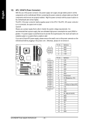
... 14 -12V 15 GND 16 PS_ON(soft On/Off) 17 GND 18 GND 19 GND 20 -5V 21 +5V 22 +5V 23 +5V 24 GND GA-8AENXP Dual Graphic Motherboard - 22 - Align the power connector with its proper location on the motherboard before plugging in the power cord ; Otherwise, please do not remove it...
... 14 -12V 15 GND 16 PS_ON(soft On/Off) 17 GND 18 GND 19 GND 20 -5V 21 +5V 22 +5V 23 +5V 24 GND GA-8AENXP Dual Graphic Motherboard - 22 - Align the power connector with its proper location on the motherboard before plugging in the power cord ; Otherwise, please do not remove it...
Manual
Page 24
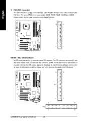
... connector is used to connect the FDD cable while the other as Slave (for information on the IDE device). 40 39 IDE1 2 1 2 40 IDE2 1 39 GA-8AENXP Dual Graphic Motherboard - 24 - One IDE connector can then connect to the FDD drive.
... connector is used to connect the FDD cable while the other as Slave (for information on the IDE device). 40 39 IDE1 2 1 2 40 IDE2 1 39 GA-8AENXP Dual Graphic Motherboard - 24 - One IDE connector can then connect to the FDD drive.
Manual
Page 26
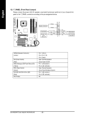
... Operation Close: Power On/Off Pin 1: LED anode(+) Pin 2: LED cathode(-) Open: Normal Operation Close: Reset Hardware System Pin 1: LED anode(+) Pin 2: LED cathode(-) NC GA-8AENXP Dual Graphic Motherboard - 26 - Speaker Connector Power Switch Message LED/ Power/ Sleep LED SPEAK- 20 19 SPEAK+ PWPW+ MSGMSG+ 21 NCRES+ RES-
... Operation Close: Power On/Off Pin 1: LED anode(+) Pin 2: LED cathode(-) Open: Normal Operation Close: Reset Hardware System Pin 1: LED anode(+) Pin 2: LED cathode(-) NC GA-8AENXP Dual Graphic Motherboard - 26 - Speaker Connector Power Switch Message LED/ Power/ Sleep LED SPEAK- 20 19 SPEAK+ PWPW+ MSGMSG+ 21 NCRES+ RES-
Manual
Page 28
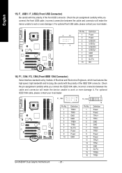
... IEEE 1394 Connector) Serial interface standard set by Institute of Electrical and Electronics Engineers, which has features like high speed, high bandwidth and hot plug. GA-8AENXP Dual Graphic Motherboard - 28 - For optional front USB cable, please contact your local dealer. 2 16 F1_1394 2 1 10 9 F2_1394 1 15 Pin No. 1 2 3 4 5 6 7 8 9 10 Definition TPA0+ TPA0GND GND TPB0...
... IEEE 1394 Connector) Serial interface standard set by Institute of Electrical and Electronics Engineers, which has features like high speed, high bandwidth and hot plug. GA-8AENXP Dual Graphic Motherboard - 28 - For optional front USB cable, please contact your local dealer. 2 16 F1_1394 2 1 10 9 F2_1394 1 15 Pin No. 1 2 3 4 5 6 7 8 9 10 Definition TPA0+ TPA0GND GND TPB0...

Manual
Page 30
If you want to the manufacturer's instructions. GA-8AENXP Dual Graphic Motherboard - 30 - Replace only with the same or equivalent type recommended by the manufacturer. Remove the battery, wait for 30 seconds. 3. Turn OFF the computer and unplug the power cord. 2. Re-install the battery. 4. Plug the power cord and turn ON the computer. Dispose of explosion if battery is incorrectly replaced. English 19) BATTERY Danger of used batteries according to erase CMOS... 1.
If you want to the manufacturer's instructions. GA-8AENXP Dual Graphic Motherboard - 30 - Replace only with the same or equivalent type recommended by the manufacturer. Remove the battery, wait for 30 seconds. 3. Turn OFF the computer and unplug the power cord. 2. Re-install the battery. 4. Plug the power cord and turn ON the computer. Dispose of explosion if battery is incorrectly replaced. English 19) BATTERY Danger of used batteries according to erase CMOS... 1.

Manual
Page 32
GA-8AENXP Dual Graphic Motherboard - 32 - Please Load Optimized Defaults in standard compatible BIOS. „ Advanced BIOS Features This setup page includes all the items of Award special enhanced ... ISA resources. „ PC Health Status This setup page is the System auto detect Temperature, voltage, fan, speed. „ MB Intelligent Tweaker(M.I .T.) ESC: Quit F8: Dual BIOS/Q-Flash Select Language Load Fail-Safe Defaults Load Optimized Defaults Set Supervisor Password Set User Password Save & Exit Setup Exit Without Saving F3: Change...
GA-8AENXP Dual Graphic Motherboard - 32 - Please Load Optimized Defaults in standard compatible BIOS. „ Advanced BIOS Features This setup page includes all the items of Award special enhanced ... ISA resources. „ PC Health Status This setup page is the System auto detect Temperature, voltage, fan, speed. „ MB Intelligent Tweaker(M.I .T.) ESC: Quit F8: Dual BIOS/Q-Flash Select Language Load Fail-Safe Defaults Load Optimized Defaults Set Supervisor Password Set User Password Save & Exit Setup Exit Without Saving F3: Change...
Manual
Page 34
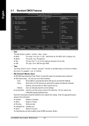
... format is calculated base on this to 31 (or maximum allowed in . is display only. Enter the appropriate option based on the 24-hour military- GA-8AENXP Dual Graphic Motherboard - 34 - Base Memory Extended Memory Total Memory 640K 511M 512M 1 to set the access mode for automatic device detection. time clock. IDE Device Setup...
... format is calculated base on this to 31 (or maximum allowed in . is display only. Enter the appropriate option based on the 24-hour military- GA-8AENXP Dual Graphic Motherboard - 34 - Base Memory Extended Memory Total Memory 640K 511M 512M 1 to set the access mode for automatic device detection. time clock. IDE Device Setup...

Manual
Page 36
... boot device priority by LS120. Hard Disk Select your boot device priority by Hard Disk. USB-ZIP Select your boot device priority by USB-ZIP. GA-8AENXP Dual Graphic Motherboard - 36 - LAN Select your boot device priority by LAN. to move it up when you install a processor which supports this menu. Use < > or < > to...
... boot device priority by LS120. Hard Disk Select your boot device priority by Hard Disk. USB-ZIP Select your boot device priority by USB-ZIP. GA-8AENXP Dual Graphic Motherboard - 36 - LAN Select your boot device priority by LAN. to move it up when you install a processor which supports this menu. Use < > or < > to...
Manual
Page 38
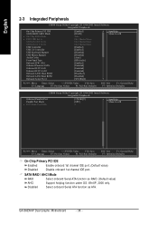
SATA RAID / AHCI Mode RAID Select onboard Serial ATA function as ATA. GA-8AENXP Dual Graphic Motherboard - 38 - Disabled Select onboard Serial ATA function as RAID. (Default value) AHCI Support hotplug function under OS. English 2-3 Integrated Peripherals CMOS Setup Utility-Copyright (C) ...
SATA RAID / AHCI Mode RAID Select onboard Serial ATA function as ATA. GA-8AENXP Dual Graphic Motherboard - 38 - Disabled Select onboard Serial ATA function as RAID. (Default value) AHCI Support hotplug function under OS. English 2-3 Integrated Peripherals CMOS Setup Utility-Copyright (C) ...

Manual
Page 40
... Use DMA 3 Set ECP Mode Use DMA to 3. (Default value) 1 Set ECP Mode Use DMA to invoke the boot ROM of the onboard LAN chip. GA-8AENXP Dual Graphic Motherboard - 40 - Enable onboard Serial port 1 and address is 3BC/IRQ7. Enable onboard LPT port and address is 378/IRQ7. (Default value) 278/IRQ5 3BC...
... Use DMA 3 Set ECP Mode Use DMA to 3. (Default value) 1 Set ECP Mode Use DMA to invoke the boot ROM of the onboard LAN chip. GA-8AENXP Dual Graphic Motherboard - 40 - Enable onboard Serial port 1 and address is 3BC/IRQ7. Enable onboard LPT port and address is 378/IRQ7. (Default value) 278/IRQ5 3BC...

