Manual
Page 1
GA-8AENXP Dual Graphic Intel® Pentium® 4 LGA775 Processor Motherboard User's Manual Rev. 1001 12ME-8AENXPDG-1001
GA-8AENXP Dual Graphic Intel® Pentium® 4 LGA775 Processor Motherboard User's Manual Rev. 1001 12ME-8AENXPDG-1001
Manual
Page 2
Motherboard GA-8AENXP Dual Graphic Feb. 4, 2005 Motherboard GA-8AENXP Dual Graphic Feb. 4, 2005
Motherboard GA-8AENXP Dual Graphic Feb. 4, 2005 Motherboard GA-8AENXP Dual Graphic Feb. 4, 2005

Manual
Page 4
Table of Contents GA-8AENXP Dual Graphic Motherboard Layout 6 Block Diagram ...7 Chapter 1 Hardware Installation 9 1-1 Considerations Prior to Installation 9 1-2 Feature Summary 10 1-3 Installation of the CPU and Heatsink 12 1-3-1 Installation of ...Northbridge Cooling Fan 14 1-5 Installation of Memory 14 1-6 Installation of Expansion Cards 16 1-7 Configuring a Quad View System 17 1-8 Installation of U-Plus DPS (Universal Plus Dual Power System 19 1-9 I/O Back Panel Introduction 20 1-10 Connectors Introduction 21 Chapter 2 BIOS Setup 31 The Main Menu (For example: BIOS Ver. : E15 32...
Table of Contents GA-8AENXP Dual Graphic Motherboard Layout 6 Block Diagram ...7 Chapter 1 Hardware Installation 9 1-1 Considerations Prior to Installation 9 1-2 Feature Summary 10 1-3 Installation of the CPU and Heatsink 12 1-3-1 Installation of ...Northbridge Cooling Fan 14 1-5 Installation of Memory 14 1-6 Installation of Expansion Cards 16 1-7 Configuring a Quad View System 17 1-8 Installation of U-Plus DPS (Universal Plus Dual Power System 19 1-9 I/O Back Panel Introduction 20 1-10 Connectors Introduction 21 Chapter 2 BIOS Setup 31 The Main Menu (For example: BIOS Ver. : E15 32...

Manual
Page 7
... TSB81BA3 RJ45 LAN1 RJ45 LAN2 Host Interface DDRII 711/600(Note)/533/400MHz DIMM Intel 925XE MCH Intel ICH6R Dual Channel Memory MCHCLK (266/200/133MHz) 100MHz 66MHz 33MHz 14.318MHz 48MHz Dual BIOS 4 Serial ATA PDC20779 2 Serial ATA II ATA33/66/100/133 IDE Channels ATA33/66/100 IDE Channels CODEC... Center/Subwoofer Speaker Out Side Speaker Out MIC Line-Out Line-In SPDIF In SPDIF Out (Note) To use a DDRII 600 memory module on the motherboard, you must install a 1066MHz FSB processor and overclock in BIOS. - 7 - To use a DDRII 711 memory module on the...
... TSB81BA3 RJ45 LAN1 RJ45 LAN2 Host Interface DDRII 711/600(Note)/533/400MHz DIMM Intel 925XE MCH Intel ICH6R Dual Channel Memory MCHCLK (266/200/133MHz) 100MHz 66MHz 33MHz 14.318MHz 48MHz Dual BIOS 4 Serial ATA PDC20779 2 Serial ATA II ATA33/66/100/133 IDE Channels ATA33/66/100 IDE Channels CODEC... Center/Subwoofer Speaker Out Side Speaker Out MIC Line-Out Line-In SPDIF In SPDIF Out (Note) To use a DDRII 600 memory module on the motherboard, you must install a 1066MHz FSB processor and overclock in BIOS. - 7 - To use a DDRII 711 memory module on the...
Manual
Page 9
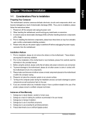
...be an unofficial Gigabyte product. - 9 - Prior to installation, please follow the instructions below: 1. Installation Notices 1. To prevent damage to the motherboard, please do not allow screws to use of uncertified components. 5. Damage due to come in contact with the motherboard circuit or its...using the product, please verify that you are required for warranty validation. 2. Please do not place the computer system on the motherboard or within a electrostatic shielding container. 5. Instances of electrostatic discharge (ESD). Damage due to the installation of the product, ...
...be an unofficial Gigabyte product. - 9 - Prior to installation, please follow the instructions below: 1. Installation Notices 1. To prevent damage to the motherboard, please do not allow screws to use of uncertified components. 5. Damage due to come in contact with the motherboard circuit or its...using the product, please verify that you are required for warranty validation. 2. Please do not place the computer system on the motherboard or within a electrostatic shielding container. 5. Instances of electrostatic discharge (ESD). Damage due to the installation of the product, ...

Manual
Page 10
... must install an 800MHz FSB processor and overclock in BIOS. GA-8AENXP Dual Graphic Motherboard - 10 - English 1-2 Feature Summary CPU Chipset Memory Slots IDE Connections FDD Connections Onboard SATA Peripherals Onboard LAN Š Supports the latest Intel® Pentium&#... certain amount of memory size will instead be shown as 3.xxGB memory during system startup. (Note 2) To use a DDRII 600 memory module on the motherboard, you must install a 1066MHz FSB processor and overclock in BIOS. For example, 4 GB of memory is reserved for system usage and therefore the actual memory...
... must install an 800MHz FSB processor and overclock in BIOS. GA-8AENXP Dual Graphic Motherboard - 10 - English 1-2 Feature Summary CPU Chipset Memory Slots IDE Connections FDD Connections Onboard SATA Peripherals Onboard LAN Š Supports the latest Intel® Pentium&#... certain amount of memory size will instead be shown as 3.xxGB memory during system startup. (Note 2) To use a DDRII 600 memory module on the motherboard, you must install a 1066MHz FSB processor and overclock in BIOS. For example, 4 GB of memory is reserved for system usage and therefore the actual memory...
Manual
Page 12
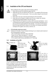
... the CPU host frequency in a straight and downwards motion. Avoid twisting or bending motions that the motherboard supports the CPU. 2. English 1-3 Installation of the CPU may occur. 5. If you wish to the CPU during installation.) GA-8AENXP Dual Graphic Motherboard - 12 - HT functionality requirement content : Enabling the functionality of the CPU Metal Lever Fig. 1 Gently lift...
... the CPU host frequency in a straight and downwards motion. Avoid twisting or bending motions that the motherboard supports the CPU. 2. English 1-3 Installation of the CPU may occur. 5. If you wish to the CPU during installation.) GA-8AENXP Dual Graphic Motherboard - 12 - HT functionality requirement content : Enabling the functionality of the CPU Metal Lever Fig. 1 Gently lift...
Manual
Page 13
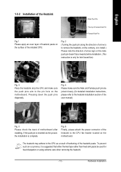
...6 Finally, please attach the power connector of the heatsink to the heatsink installation section of the user manual) Fig. 5 Please check the back of motherboard after installing. Fig. 2 (Turning the push pin along the direction of arrow is to remove the heatsink, on the contrary, is complete. The ... the push pins aim to the CPU as the picture, the installation is to install.) Please note the direction of arrow sign on the motherboard. To prevent such an occurrence, it is inserted as a result of hardening of the heatsink paste. English 1-3-2 Installation of the Heatsink Male...
...6 Finally, please attach the power connector of the heatsink to the heatsink installation section of the user manual) Fig. 5 Please check the back of motherboard after installing. Fig. 2 (Turning the push pin along the direction of arrow is to remove the heatsink, on the contrary, is complete. The ... the push pins aim to the CPU as the picture, the installation is to install.) Please note the direction of arrow sign on the motherboard. To prevent such an occurrence, it is inserted as a result of hardening of the heatsink paste. English 1-3-2 Installation of the Heatsink Male...

Manual
Page 14
... might cause the side extensions to break-off to prevent hardware damage. 3. The motherboard supports DDR II memory modules, whereby BIOS will automatically detect memory capacity and specifications. GA-8AENXP Dual Graphic Motherboard - 14 - Fig.2 Once the fan is supported by the motherboard. If you are designed so that they can be inserted only in only one...
... might cause the side extensions to break-off to prevent hardware damage. 3. The motherboard supports DDR II memory modules, whereby BIOS will automatically detect memory capacity and specifications. GA-8AENXP Dual Graphic Motherboard - 14 - Fig.2 Once the fan is supported by the motherboard. If you are designed so that they can be inserted only in only one...
Manual
Page 16
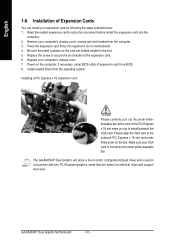
... your expansion card by the small white-drawable bar. The GA-8AENXP Dual Graphic will allow a four-monitor configuration(Quad View) when used in conjunction with two PCI Express graphics cards that are indeed seated in motherboard. 4. Replace the screw to secure the slot bracket of ...computer's chassis cover, screws and slot bracket from the operating system. Please align the VGA card to install/uninstall the VGA card. GA-8AENXP Dual Graphic Motherboard - 16 - Replace your VGA card is locked by following the steps outlined below: 1. Make sure your computer's chassis cover....
... your expansion card by the small white-drawable bar. The GA-8AENXP Dual Graphic will allow a four-monitor configuration(Quad View) when used in conjunction with two PCI Express graphics cards that are indeed seated in motherboard. 4. Replace the screw to secure the slot bracket of ...computer's chassis cover, screws and slot bracket from the operating system. Please align the VGA card to install/uninstall the VGA card. GA-8AENXP Dual Graphic Motherboard - 16 - Replace your VGA card is locked by following the steps outlined below: 1. Make sure your computer's chassis cover....
Manual
Page 17
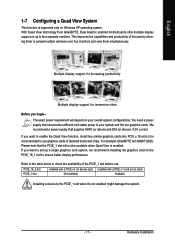
... to your overall system configurations. Refer to the table below to check the availability of the PCIE_1 slot before use graphics cards of the user by allowing them to the PCIE_1 slot when it is supported only on Windows XP operating system... to ensure better display performance. With Quad View technology from GIGABYTE, Dual Graphic enabled motherboards offer multiple display support on up a single graphics card system, we recommend installing the graphics card on your system and the two graphics cards. If you begin-- This improves the capabilities and productivity...
... to your overall system configurations. Refer to the table below to check the availability of the PCIE_1 slot before use graphics cards of the user by allowing them to the PCIE_1 slot when it is supported only on Windows XP operating system... to ensure better display performance. With Quad View technology from GIGABYTE, Dual Graphic enabled motherboards offer multiple display support on up a single graphics card system, we recommend installing the graphics card on your system and the two graphics cards. If you begin-- This improves the capabilities and productivity...
Manual
Page 18
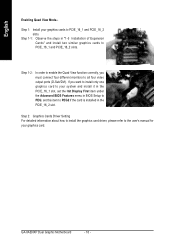
...BIOS Features menu in BIOS Setup to PCIE_16_1 and PCIE_16_2 slots. Step 1: Install your graphics card. Step 1-2: In order to enable the Quad View function correctly, you want to install only one graphics card to your system and install it in the PCIE_16_1 slot, set this item ...to PEG2 if the card is installed in "1-5 Installation of Expansion Cards" and install two similar graphics cards to all four video output ports (D-Sub/DVI). GA-8AENXP Dual Graphic Motherboard - 18 - If you must connect four different monitors to PCIE_16_1 and PCIE_16_2 slots.
...BIOS Features menu in BIOS Setup to PCIE_16_1 and PCIE_16_2 slots. Step 1: Install your graphics card. Step 1-2: In order to enable the Quad View function correctly, you want to install only one graphics card to your system and install it in the PCIE_16_1 slot, set this item ...to PEG2 if the card is installed in "1-5 Installation of Expansion Cards" and install two similar graphics cards to all four video output ports (D-Sub/DVI). GA-8AENXP Dual Graphic Motherboard - 18 - If you must connect four different monitors to PCIE_16_1 and PCIE_16_2 slots.
Manual
Page 19
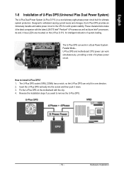
.... Reverse the installation steps if you want to install U-Plus DPS? 1. English 1-8 Installation of U-Plus DPS (Universal Plus Dual Power System) The U-Plus Dual Power System (U-Plus D.P.S.) is a revolutionary eight-phase power circuit built for intelligent indication of 8-phase power circuit. As well,...stability. The U-Plus DPS socket (VRM_CONN) has a notch, so the U-Plus DPS can only fit in a Dual Power System: Parallel Mode-U-Plus DPS and motherboard CPU power can work in one direction. 2. Hardware Installation The U-Plus DPS can work simultaneously, providing a total...
.... Reverse the installation steps if you want to install U-Plus DPS? 1. English 1-8 Installation of U-Plus DPS (Universal Plus Dual Power System) The U-Plus Dual Power System (U-Plus D.P.S.) is a revolutionary eight-phase power circuit built for intelligent indication of 8-phase power circuit. As well,...stability. The U-Plus DPS socket (VRM_CONN) has a notch, so the U-Plus DPS can only fit in a Dual Power System: Parallel Mode-U-Plus DPS and motherboard CPU power can work in one direction. 2. Hardware Installation The U-Plus DPS can work simultaneously, providing a total...

Manual
Page 20
... or device(s) vendors. Line Out (Front Speaker Out) Connect the stereo speakers, earphone or front surround speakers to serial-based mouse or data processing devices. GA-8AENXP Dual Graphic Motherboard - 20 - Parallel Port The parallel port allows connection of 10/100/ 1000Mbps. SPDIF_O (SPDIF Out) The SPDIF output is Gigabit Ethernet, providing data transfer speeds...
... or device(s) vendors. Line Out (Front Speaker Out) Connect the stereo speakers, earphone or front surround speakers to serial-based mouse or data processing devices. GA-8AENXP Dual Graphic Motherboard - 20 - Parallel Port The parallel port allows connection of 10/100/ 1000Mbps. SPDIF_O (SPDIF Out) The SPDIF output is Gigabit Ethernet, providing data transfer speeds...
Manual
Page 22
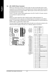
... . If the ATX_12V power connector is able to handle the system voltage requirements. Caution! If you use a power supply that all the components on the motherboard and connect tightly. Otherwise, please do not remove it. 42 31 Pin No. 1 2 3 4 Definition GND GND +12V +12V Pin No. The ... -12V 15 GND 16 PS_ON(soft On/Off) 17 GND 18 GND 19 GND 20 -5V 21 +5V 22 +5V 23 +5V 24 GND GA-8AENXP Dual Graphic Motherboard - 22 - English 1/2) ATX_12V/ATX (Power Connector) With the use of the power connector, the power supply can withstand high power consumption be used...
... . If the ATX_12V power connector is able to handle the system voltage requirements. Caution! If you use a power supply that all the components on the motherboard and connect tightly. Otherwise, please do not remove it. 42 31 Pin No. 1 2 3 4 Definition GND GND +12V +12V Pin No. The ... -12V 15 GND 16 PS_ON(soft On/Off) 17 GND 18 GND 19 GND 20 -5V 21 +5V 22 +5V 23 +5V 24 GND GA-8AENXP Dual Graphic Motherboard - 22 - English 1/2) ATX_12V/ATX (Power Connector) With the use of the power connector, the power supply can withstand high power consumption be used...
Manual
Page 24
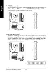
... an IDE connector. If you wish to connect two IDE devices, please set the jumper on the IDE device). 40 39 IDE1 2 1 2 40 IDE2 1 39 GA-8AENXP Dual Graphic Motherboard - 24 - The types of the cable connects to the FDD drive. One IDE connector can then connect to two IDE devices (hard drive or optical...
... an IDE connector. If you wish to connect two IDE devices, please set the jumper on the IDE device). 40 39 IDE1 2 1 2 40 IDE2 1 39 GA-8AENXP Dual Graphic Motherboard - 24 - The types of the cable connects to the FDD drive. One IDE connector can then connect to two IDE devices (hard drive or optical...
Manual
Page 26
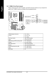
... Operation Close: Power On/Off Pin 1: LED anode(+) Pin 2: LED cathode(-) Open: Normal Operation Close: Reset Hardware System Pin 1: LED anode(+) Pin 2: LED cathode(-) NC GA-8AENXP Dual Graphic Motherboard - 26 - English 12) F_PANEL (Front Panel Jumper) Please connect the power LED, PC speaker, reset switch and power switch etc of your chassis front panel...
... Operation Close: Power On/Off Pin 1: LED anode(+) Pin 2: LED cathode(-) Open: Normal Operation Close: Reset Hardware System Pin 1: LED anode(+) Pin 2: LED cathode(-) NC GA-8AENXP Dual Graphic Motherboard - 26 - English 12) F_PANEL (Front Panel Jumper) Please connect the power LED, PC speaker, reset switch and power switch etc of your chassis front panel...
Manual
Page 28
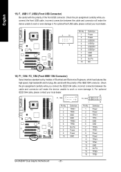
... GND Pin No. 1 2 3 4 5 6 7 8 9 10 11 12 13 14 15 16 Definition Power Power TPA1+ TPA1GND GND TPB1+ TPB1Power Power TPA2+ TPA2GND No Pin TPB2+ TPB2- GA-8AENXP Dual Graphic Motherboard - 28 - For optional IEEE1394 cable, please contact your local dealer. 2 10 1 9 Pin No. 1 2 3 4 5 6 7 8 9 10 Definition Power Power USB DXUSB DyUSB DX+ USB Dy+ GND GND...
... GND Pin No. 1 2 3 4 5 6 7 8 9 10 11 12 13 14 15 16 Definition Power Power TPA1+ TPA1GND GND TPB1+ TPB1Power Power TPA2+ TPA2GND No Pin TPB2+ TPB2- GA-8AENXP Dual Graphic Motherboard - 28 - For optional IEEE1394 cable, please contact your local dealer. 2 10 1 9 Pin No. 1 2 3 4 5 6 7 8 9 10 Definition Power Power USB DXUSB DyUSB DX+ USB Dy+ GND GND...

Manual
Page 30
Turn OFF the computer and unplug the power cord. 2. GA-8AENXP Dual Graphic Motherboard - 30 - Re-install the battery. 4. Dispose of explosion if battery is incorrectly replaced. If you want to the manufacturer's instructions. English 19) BATTERY Danger of used batteries according to erase CMOS... 1. Replace only with the same or equivalent type recommended by the manufacturer. Remove the battery, wait for 30 seconds. 3. Plug the power cord and turn ON the computer.
Turn OFF the computer and unplug the power cord. 2. GA-8AENXP Dual Graphic Motherboard - 30 - Re-install the battery. 4. Dispose of explosion if battery is incorrectly replaced. If you want to the manufacturer's instructions. English 19) BATTERY Danger of used batteries according to erase CMOS... 1. Replace only with the same or equivalent type recommended by the manufacturer. Remove the battery, wait for 30 seconds. 3. Plug the power cord and turn ON the computer.

Manual
Page 31
... highlighted item. Status Page Setup Menu / Option Page Setup Menu Press F1 to a new BIOS, either GIGABYTE's Q-Flash or @BIOS utility can enter the BIOS setup screen by pressing "Ctrl + F1". To exit... . - 31 - When the power is turned off, the battery on -line description of the motherboard. BIOS Setup If you to be used. CONTROL KEYS Move to activate certain system features. The CMOS... directly download and update BIOS from BIOS default table Load the Optimized Defaults Dual BIOS/Q-Flash utility System Information Save all the CMOS changes, only for Option...
... highlighted item. Status Page Setup Menu / Option Page Setup Menu Press F1 to a new BIOS, either GIGABYTE's Q-Flash or @BIOS utility can enter the BIOS setup screen by pressing "Ctrl + F1". To exit... . - 31 - When the power is turned off, the battery on -line description of the motherboard. BIOS Setup If you to be used. CONTROL KEYS Move to activate certain system features. The CMOS... directly download and update BIOS from BIOS default table Load the Optimized Defaults Dual BIOS/Q-Flash utility System Information Save all the CMOS changes, only for Option...


