
Manual
Page 1
GA-7PESH1 GA-7PESH2 Dual LGA2011 sockets motherboard for Intel® E5-2600 series processors User's Manual Rev. 1001
GA-7PESH1 GA-7PESH2 Dual LGA2011 sockets motherboard for Intel® E5-2600 series processors User's Manual Rev. 1001

Manual
Page 3
Table of Contents Box Contents...4 GA-7PESH1/7PESH2 Motherboard Layout 5 Chapter 1 Hardware Installation 8 1-1 Installation Precautions 8 1-2 Product Specifications 9 1-3 Installing the CPU and CPU Cooler 11 1-3-1 Installing the CPU...11 1-3-2 Installing the CPU Cooler 13 1-4 Installing the Memory 14 1-4-1 Four Channel Memory Configuration 14 1-4-2 Installing a Memory 15 1-4-3 DIMM Population Table 15 1-5 Back Panel Connectors 16 1-6 Internal Connectors 18 1-7 Jumper Setting 29 - 3 -
Table of Contents Box Contents...4 GA-7PESH1/7PESH2 Motherboard Layout 5 Chapter 1 Hardware Installation 8 1-1 Installation Precautions 8 1-2 Product Specifications 9 1-3 Installing the CPU and CPU Cooler 11 1-3-1 Installing the CPU...11 1-3-2 Installing the CPU Cooler 13 1-4 Installing the Memory 14 1-4-1 Four Channel Memory Configuration 14 1-4-2 Installing a Memory 15 1-4-3 DIMM Population Table 15 1-5 Back Panel Connectors 16 1-6 Internal Connectors 18 1-7 Jumper Setting 29 - 3 -
Manual
Page 4
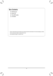
Box Contents Motherboard Driver CD Two SATA cables I/O Shield • The box contents above are subject to change without notice. • The motherboard image is for reference only and the actual items shall depend on the product package you obtain. The box contents are for reference only. - 4 -
Box Contents Motherboard Driver CD Two SATA cables I/O Shield • The box contents above are subject to change without notice. • The motherboard image is for reference only and the actual items shall depend on the product package you obtain. The box contents are for reference only. - 4 -

Manual
Page 5
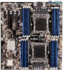
GA-7PESH1/7PESH2 Motherboard Layout 41 42 44 45 47 49 51 1 2 3 4 5 6 43 46 48 50 40 39 38 37 36 35 34 60 52 59 53 54 33 58 32 55 31 30 57 56 29 28 25 24 89 7 10 11 12 13 14 19 18 15 27 26 23 22 21 20 17 16 - 5 -
GA-7PESH1/7PESH2 Motherboard Layout 41 42 44 45 47 49 51 1 2 3 4 5 6 43 46 48 50 40 39 38 37 36 35 34 60 52 59 53 54 33 58 32 55 31 30 57 56 29 28 25 24 89 7 10 11 12 13 14 19 18 15 27 26 23 22 21 20 17 16 - 5 -
Manual
Page 7
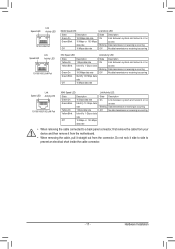
... SATA_DOM0 and SATA_DOM1 jumper setting instruction. - 7 - Please refer to reduce any risk of hard disk damage. If a SATA type hard drive is connected to the motherboard, please ensure the jumper is closed and set to 2-3 pins (Normal mode), in order to Page 33 for secondary CPU) CPU1 fan cable connector Battery...
... SATA_DOM0 and SATA_DOM1 jumper setting instruction. - 7 - Please refer to reduce any risk of hard disk damage. If a SATA type hard drive is connected to the motherboard, please ensure the jumper is closed and set to 2-3 pins (Normal mode), in order to Page 33 for secondary CPU) CPU1 fan cable connector Battery...
Manual
Page 8
... been turned off. • Before turning on the power, make sure they are connected tightly and securely. • When handling the motherboard, avoid touching any installation steps or have a problem related to the use of electrostatic discharge (ESD). These stickers are required for warranty validation...computer system on an uneven surface. • Do not place the computer system in a high-temperature environment. • Turning on the motherboard, make sure the power supply voltage has been set according to the local voltage standard. • Before using the product, please verify ...
... been turned off. • Before turning on the power, make sure they are connected tightly and securely. • When handling the motherboard, avoid touching any installation steps or have a problem related to the use of electrostatic discharge (ESD). These stickers are required for warranty validation...computer system on an uneven surface. • Do not place the computer system in a high-temperature environment. • Turning on the motherboard, make sure the power supply voltage has been set according to the local voltage standard. • Before using the product, please verify ...

Manual
Page 11
... Key Alignment Key LGA2011 CPU Notch Notch Triangle Pin One Marking on the computer if the CPU cooler is not recommended that the motherboard supports the CPU. (Go to GIGABYTE's website for the peripherals. The CPU cannot be set the frequency beyond hardware specifications since it does not meet the standard requirements...
... Key Alignment Key LGA2011 CPU Notch Notch Triangle Pin One Marking on the computer if the CPU cooler is not recommended that the motherboard supports the CPU. (Go to GIGABYTE's website for the peripherals. The CPU cannot be set the frequency beyond hardware specifications since it does not meet the standard requirements...
Manual
Page 12
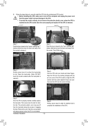
... - Remove the cover. B. Step 5: Once the CPU is opened.) Step 4: Hold the CPU with the socket alignment keys) and carefully insert the CPU into the motherboard CPU socket. •• Before installing the CPU, make sure to rise. Save the cover properly and always replace it if the CPU is inserted...
... - Remove the cover. B. Step 5: Once the CPU is opened.) Step 4: Hold the CPU with the socket alignment keys) and carefully insert the CPU into the motherboard CPU socket. •• Before installing the CPU, make sure to rise. Save the cover properly and always replace it if the CPU is inserted...
Manual
Page 13
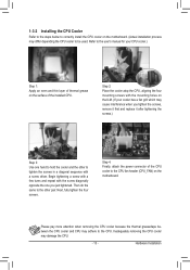
1-3-2 Installing the CPU Cooler Refer to the steps below to correctly install the CPU cooler on the motherboard. (Actual installation process may differ depending the CPU cooler to the CPU. Begin tightening a screw with a few turns and repeat with the screw diagonally opposite ... a diagonal sequence with the mounting holes on the ILM. (If your CPU cooler.) Step 1: Apply an even and thin layer of thermal grease on the motherboard. Refer to the user's manual for your cooler has a fan grill which may cause interference when you just tightened. Next, fully tighten the four screws...
1-3-2 Installing the CPU Cooler Refer to the steps below to correctly install the CPU cooler on the motherboard. (Actual installation process may differ depending the CPU cooler to the CPU. Begin tightening a screw with a few turns and repeat with the screw diagonally opposite ... a diagonal sequence with the mounting holes on the ILM. (If your CPU cooler.) Step 1: Apply an even and thin layer of thermal grease on the motherboard. Refer to the user's manual for your cooler has a fan grill which may cause interference when you just tightened. Next, fully tighten the four screws...
Manual
Page 14
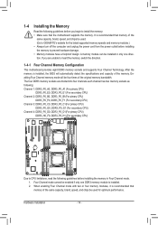
...Channel memory mode will automatically detect the specifications and capacity of the same capacity, brand, speed, and chips be used . (Go to GIGABYTE's website for optimum performance. Four Channel mode cannot be enabled if only one direction. Hardware Installation - 14 - 1-4 Installing the Memory ... in Four Channel mode. 1. If you begin to insert the memory, switch the direction. 1-4-1 Four Channel Memory Configuration This motherboard provides eight DDR3 memory sockets and supports Four Channel Technology. When enabling Four Channel mode with two or four memory modules, it...
...Channel memory mode will automatically detect the specifications and capacity of the same capacity, brand, speed, and chips be used . (Go to GIGABYTE's website for optimum performance. Four Channel mode cannot be enabled if only one direction. Hardware Installation - 14 - 1-4 Installing the Memory ... in Four Channel mode. 1. If you begin to insert the memory, switch the direction. 1-4-1 Four Channel Memory Configuration This motherboard provides eight DDR3 memory sockets and supports Four Channel Technology. When enabling Four Channel mode with two or four memory modules, it...
Manual
Page 15
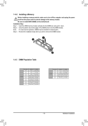
... from the power outlet to prevent damage to lock the DIMM module. Reverse the installation steps when you wish to install DDR3 DIMMs on this motherboard. Be sure to remove the DIMM module. 1 2 1-4-3 DIMM Population Table R-DIMM 1N or 2N 1N 1N 1N 1N 1N 1N 1N 1N 1N DIMM1 Empty...
... from the power outlet to prevent damage to lock the DIMM module. Reverse the installation steps when you wish to install DDR3 DIMMs on this motherboard. Be sure to remove the DIMM module. 1 2 1-4-3 DIMM Population Table R-DIMM 1N or 2N 1N 1N 1N 1N 1N 1N 1N 1N 1N DIMM1 Empty...
Manual
Page 17
Do not rock it straight out from the motherboard. • When removing the cable, pull it side to side to prevent an electrical short inside the cable connector. - 17 - Hardware Installation Speed LED Link ...
Do not rock it straight out from the motherboard. • When removing the cable, pull it side to side to prevent an electrical short inside the cable connector. - 17 - Hardware Installation Speed LED Link ...

Manual
Page 19
Read the following guidelines before turning on the computer, make sure your computer. Unplug the power cord from the power outlet to prevent damage to the devices. • After installing the device and before connecting external devices: • First make sure the device cable has been securely attached to turn off the devices and your devices are compliant with the connectors you wish to connect. • Before installing the devices, be sure to the connector on the motherboard. - 19 - Hardware Installation
Read the following guidelines before turning on the computer, make sure your computer. Unplug the power cord from the power outlet to prevent damage to the devices. • After installing the device and before connecting external devices: • First make sure the device cable has been securely attached to turn off the devices and your devices are compliant with the connectors you wish to connect. • Before installing the devices, be sure to the connector on the motherboard. - 19 - Hardware Installation
Manual
Page 20
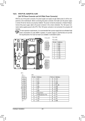
... the correct orientation. Connect the power supply cable to the CPU. If the 12V power connector is turned off and all the components on the motherboard. 1/2/3) ATX1/P12V_AUX2/P12V_AUX1 (2x4 12V Power Connector and 2x12 Main Power Connector) With the use of the power connector, the power supply can supply enough...
... the correct orientation. Connect the power supply cable to the CPU. If the 12V power connector is turned off and all the components on the motherboard. 1/2/3) ATX1/P12V_AUX2/P12V_AUX1 (2x4 12V Power Connector and 2x12 Main Power Connector) With the use of the power connector, the power supply can supply enough...
Manual
Page 21
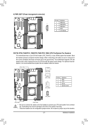
... connector) 1 5 Pin No. 1 2 3 4 5 Definition SMB CLK SMB DATA SMB Alert GND 3.3V Sense 5/6/7/8) CPU0_FAN/CPU1_FAN/SYS_FAN1/SYS_FAN2 (CPU Fan/System Fan Headers) The motherboard has a 4-pin CPU fan header (CPU_FAN1/2), a 4-pin (FAN4) system fan headers. For optimum heat dissipation, it in damage to prevent your CPU and system from...a system fan be sure to connect it is the ground wire). When connecting a fan cable, be installed inside the chassis. Hardware Installation The motherboard supports CPU fan speed control, which requires the use of a CPU fan with fan speed control design.
... connector) 1 5 Pin No. 1 2 3 4 5 Definition SMB CLK SMB DATA SMB Alert GND 3.3V Sense 5/6/7/8) CPU0_FAN/CPU1_FAN/SYS_FAN1/SYS_FAN2 (CPU Fan/System Fan Headers) The motherboard has a 4-pin CPU fan header (CPU_FAN1/2), a 4-pin (FAN4) system fan headers. For optimum heat dissipation, it in damage to prevent your CPU and system from...a system fan be sure to connect it is the ground wire). When connecting a fan cable, be installed inside the chassis. Hardware Installation The motherboard supports CPU fan speed control, which requires the use of a CPU fan with fan speed control design.

Manual
Page 30
Failure to do so may cause damage to the motherboard. • After system restart, go to BIOS Setup Exit menu and load factory defaults (select Load Default Values) or manually configure the BIOS settings (refer ...
Failure to do so may cause damage to the motherboard. • After system restart, go to BIOS Setup Exit menu and load factory defaults (select Load Default Values) or manually configure the BIOS settings (refer ...
Manual
Page 33
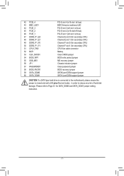
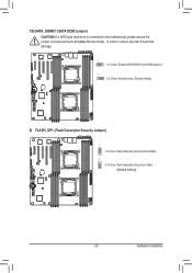
If a SATA type hard drive is connected to the motherboard, please ensure the jumper is closed and set to 2-3 pins (Normal mode), in order to reduce any risk of hard disk damage. 1 1-2 Close: Enable SATA0/SATA1 port DOM support. 1 2-3 Close: Normal mode. (Default setting) 9) FLASH_DP1 (Flash Descriptor Security Jumper) 1 1-2 Close: Flash Descriptor Security Overridden 1 2-3 Close: Flash Descriptor Security in effect. (Default setting) - 33 - Hardware Installation 7/8) SATA_DOM0/1 (SATA DOM Jumper) CAUTION!
If a SATA type hard drive is connected to the motherboard, please ensure the jumper is closed and set to 2-3 pins (Normal mode), in order to reduce any risk of hard disk damage. 1 1-2 Close: Enable SATA0/SATA1 port DOM support. 1 2-3 Close: Normal mode. (Default setting) 9) FLASH_DP1 (Flash Descriptor Security Jumper) 1 1-2 Close: Flash Descriptor Security Overridden 1 2-3 Close: Flash Descriptor Security in effect. (Default setting) - 33 - Hardware Installation 7/8) SATA_DOM0/1 (SATA DOM Jumper) CAUTION!
Manual
Page 34
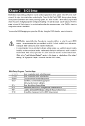
... this chapter or introductions of the battery/ clearing CMOS jumper in the CMOS. Inadequate BIOS flashing may result in the EFI on the motherboard supplies the necessary power to the CMOS to keep the configuration values in Chapter 1 for the current submenus Save all the changes and ... activate certain system features. Inadequately altering the settings may result in system malfunction. • It is turned off, the battery on the motherboard. BIOS includes a BIOS Setup program that you not alter the default settings (unless you do it is recommended that you don't flash the BIOS...
... this chapter or introductions of the battery/ clearing CMOS jumper in the CMOS. Inadequate BIOS flashing may result in the EFI on the motherboard supplies the necessary power to the CMOS to keep the configuration values in Chapter 1 for the current submenus Save all the changes and ... activate certain system features. Inadequately altering the settings may result in system malfunction. • It is turned off, the battery on the motherboard. BIOS includes a BIOS Setup program that you not alter the default settings (unless you do it is recommended that you don't flash the BIOS...
Manual
Page 52
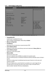
...in parallel. BIOS Setup - 52 - Memory mode can be determined in place of memory to run the same set to Lockstep mode, the motherboard uses two areas of the failed memory. The spare memory is used as active memory in Memory Mode item. When set to Sparing mode,... a preset threshold of all DIMMs are available to trigger fail-over. When set to Mirroring mode, the motherboard maintains two identical (redundant) copies of coorectable errors is put online and used to the operation system. Current Memory Speed Displays the cuurent ...
...in parallel. BIOS Setup - 52 - Memory mode can be determined in place of memory to run the same set to Lockstep mode, the motherboard uses two areas of the failed memory. The spare memory is used as active memory in Memory Mode item. When set to Sparing mode,... a preset threshold of all DIMMs are available to trigger fail-over. When set to Mirroring mode, the motherboard maintains two identical (redundant) copies of coorectable errors is put online and used to the operation system. Current Memory Speed Displays the cuurent ...


