Manual
Page 1
GA-785GMT-USB3 AM3 socket motherboard for AMD Phenom™ II processor/ AMD Athlon™ II processor User's Manual Rev. 1001 12ME-785TB3-1001R
GA-785GMT-USB3 AM3 socket motherboard for AMD Phenom™ II processor/ AMD Athlon™ II processor User's Manual Rev. 1001 12ME-785TB3-1001R
Manual
Page 2
Motherboard GA-785GMT-USB3 Jan 16, 2010 Motherboard GA-785GMT-USB3 Jan. 16, 2010
Motherboard GA-785GMT-USB3 Jan 16, 2010 Motherboard GA-785GMT-USB3 Jan. 16, 2010
Manual
Page 3
... or download the information on/from the Support&Downloads\Motherboard\Technology Guide page on our website. For product-related information, check on our website at: http://www.gigabyte.com.tw Identifying Your Motherboard Revision The revision number on how to their respective owners.... Example: The trademarks mentioned in any form or by GIGABYTE without GIGABYTE's prior written permission. All rights reserved. Copyright &#...
... or download the information on/from the Support&Downloads\Motherboard\Technology Guide page on our website. For product-related information, check on our website at: http://www.gigabyte.com.tw Identifying Your Motherboard Revision The revision number on how to their respective owners.... Example: The trademarks mentioned in any form or by GIGABYTE without GIGABYTE's prior written permission. All rights reserved. Copyright &#...
Manual
Page 4
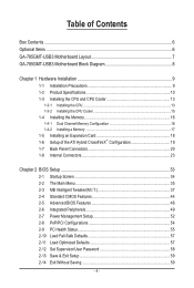
Table of Contents Box Contents...6 Optional Items...6 GA-785GMT-USB3 Motherboard Layout 7 GA-785GMT-USB3 Motherboard Block Diagram 8 Chapter 1 Hardware Installation 9 1-1 Installation Precautions 9 1-2 Product Specifications 10 1-3 Installing the CPU and CPU Cooler 13 1-3-1 Installing the CPU 13 1-3-2 Installing the CPU Cooler ...
Table of Contents Box Contents...6 Optional Items...6 GA-785GMT-USB3 Motherboard Layout 7 GA-785GMT-USB3 Motherboard Block Diagram 8 Chapter 1 Hardware Installation 9 1-1 Installation Precautions 9 1-2 Product Specifications 10 1-3 Installing the CPU and CPU Cooler 13 1-3-1 Installing the CPU 13 1-3-2 Installing the CPU Cooler ...
Manual
Page 6
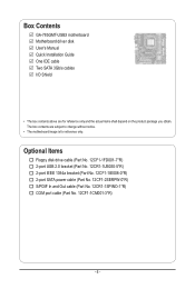
... SATA power cable (Part No. 12CF1-2SERPW-0*R) S/PDIF In and Out cable (Part No. 12CR1-1SPINO-1*R) COM port cable (Part No. 12CF1-1CM001-3*R) - 6 - Box Contents GA-785GMT-USB3 motherboard Motherboard driver disk User's Manual Quick Installation Guide One IDE cable Two SATA 3Gb/s cables I/O Shield • The box contents above are subject to change without...
... SATA power cable (Part No. 12CF1-2SERPW-0*R) S/PDIF In and Out cable (Part No. 12CR1-1SPINO-1*R) COM port cable (Part No. 12CF1-1CM001-3*R) - 6 - Box Contents GA-785GMT-USB3 motherboard Motherboard driver disk User's Manual Quick Installation Guide One IDE cable Two SATA 3Gb/s cables I/O Shield • The box contents above are subject to change without...
Manual
Page 7
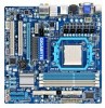
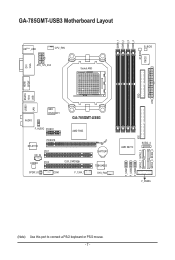
FDD ATX GA-785GMT-USB3 Motherboard Layout DDR3_1 DDR3_2 DDR3_3 DDR3_4 M_BIOS IT8720 DVI VGA KB(Note)_USB CPU_FAN ATX_12V_2X4 Socket AM3 B_BIOS SPDIF HDMI USB 1394 USB30 ESATA LAN AUDIO NEC D720200F1 F_AUDIO PCIEX1 GA-785GMT-USB3 AMD 785G PCIEX16 RTL8111D PCI1 CD_IN CODEC PCI2 CLR_CMOS SPDIF_IO COM F_1394_1 BATTERY TSB43AB23 SYS_FAN AMD SB710 SATA2_4 SATA2_1 SATA2_3 F_USB3 F_USB2 F_USB1 F_PANEL IDE SATA2_0 SATA2_2 (Note) Use this port to connect a PS/2 keyboard or PS/2 mouse. - 7 -
FDD ATX GA-785GMT-USB3 Motherboard Layout DDR3_1 DDR3_2 DDR3_3 DDR3_4 M_BIOS IT8720 DVI VGA KB(Note)_USB CPU_FAN ATX_12V_2X4 Socket AM3 B_BIOS SPDIF HDMI USB 1394 USB30 ESATA LAN AUDIO NEC D720200F1 F_AUDIO PCIEX1 GA-785GMT-USB3 AMD 785G PCIEX16 RTL8111D PCI1 CD_IN CODEC PCI2 CLR_CMOS SPDIF_IO COM F_1394_1 BATTERY TSB43AB23 SYS_FAN AMD SB710 SATA2_4 SATA2_1 SATA2_3 F_USB3 F_USB2 F_USB1 F_PANEL IDE SATA2_0 SATA2_2 (Note) Use this port to connect a PS/2 keyboard or PS/2 mouse. - 7 -
Manual
Page 8
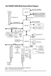
GA-785GMT-USB3 Motherboard Block Diagram PCIe CLK (100 MHz) 1 PCI Express x16 CPU CLK+/- (200 MHz) AM3 CPU DDR3 1800 (O.C.)/1333/1066 MHz Dual Channel Memory Hyper Transport 3.0 ...
GA-785GMT-USB3 Motherboard Block Diagram PCIe CLK (100 MHz) 1 PCI Express x16 CPU CLK+/- (200 MHz) AM3 CPU DDR3 1800 (O.C.)/1333/1066 MHz Dual Channel Memory Hyper Transport 3.0 ...
Manual
Page 9
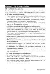
... have an ESD wrist strap, keep your hands dry and first touch a metal object to eliminate static electricity. • Prior to installing the motherboard, please have it on top of an antistatic pad or within the computer casing. • Do not place the computer system on an uneven...power supply has been turned off. • Before turning on the power, make sure they are connected tightly and securely. • When handling the motherboard, avoid touching any installation steps or have a problem related to the use of electrostatic discharge (ESD). ponents such as a result of the product, ...
... have an ESD wrist strap, keep your hands dry and first touch a metal object to eliminate static electricity. • Prior to installing the motherboard, please have it on top of an antistatic pad or within the computer casing. • Do not place the computer system on an uneven...power supply has been turned off. • Before turning on the power, make sure they are connected tightly and securely. • When handling the motherboard, avoid touching any installation steps or have a problem related to the use of electrostatic discharge (ESD). ponents such as a result of the product, ...

Manual
Page 12
... CPU/system fan speed control function is supported will depend on the CPU/system cooler you install. (Note 6) Available functions in EasyTune may differ by motherboard model. Hardware Installation - 12 -
... CPU/system fan speed control function is supported will depend on the CPU/system cooler you install. (Note 6) Available functions in EasyTune may differ by motherboard model. Hardware Installation - 12 -
Manual
Page 13
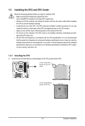
... meet the standard requirements for the latest CPU support list.) • Always turn on the computer if the CPU cooler is not recommended that the motherboard supports the CPU. (Go to install the CPU: • Make sure that the system bus frequency be inserted if oriented incorrectly. (Or you begin to...
... meet the standard requirements for the latest CPU support list.) • Always turn on the computer if the CPU cooler is not recommended that the motherboard supports the CPU. (Go to install the CPU: • Make sure that the system bus frequency be inserted if oriented incorrectly. (Or you begin to...
Manual
Page 14
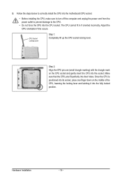
... CPU, lowering the locking lever and latching it into the socket. Hardware Installation - 14 - Follow the steps below to correctly install the CPU into the motherboard CPU socket. • Before installing the CPU, make sure to turn off the computer and unplug the power cord from the power outlet to prevent...
... CPU, lowering the locking lever and latching it into the socket. Hardware Installation - 14 - Follow the steps below to correctly install the CPU into the motherboard CPU socket. • Before installing the CPU, make sure to turn off the computer and unplug the power cord from the power outlet to prevent...
Manual
Page 15
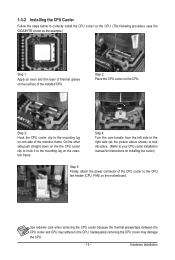
... frame. 1-3-2 Installing the CPU Cooler Follow the steps below to correctly install the CPU cooler on the CPU. (The following procedure uses the GIGABYTE cooler as the picture above shows) to lock into place. (Refer to your CPU cooler installation manual for instructions on installing the cooler.) Step... 5: Finally, attach the power connector of the CPU cooler to the CPU fan header (CPU_FAN) on the motherboard. Step 4: Turn the cam handle from the left side to the CPU. Use extreme care when removing the CPU cooler because the thermal ...
... frame. 1-3-2 Installing the CPU Cooler Follow the steps below to correctly install the CPU cooler on the CPU. (The following procedure uses the GIGABYTE cooler as the picture above shows) to lock into place. (Refer to your CPU cooler installation manual for instructions on installing the cooler.) Step... 5: Finally, attach the power connector of the CPU cooler to the CPU fan header (CPU_FAN) on the motherboard. Step 4: Turn the cam handle from the left side to the CPU. Use extreme care when removing the CPU cooler because the thermal ...
Manual
Page 16
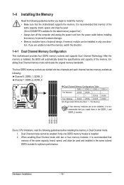
...if only one direction. If you install them in only one DDR3 memory module is recommended that you are to be used . (Go to GIGABYTE's website for optimum performance. DS/SS DS/SS Four Modules DS/SS DS/SS DS/SS DS/SS (SS=Single-Sided, DS=Double-...Sided, "- -"=No Memory) If two memory modules are unable to insert the memory, switch the direction. 1-4-1 Dual Channel Memory Configuration This motherboard provides four DDR3 memory sockets and supports Dual Channel Technology. Hardware Installation - 16 - After the memory is recommended that memory of the memory. When...
...if only one direction. If you install them in only one DDR3 memory module is recommended that you are to be used . (Go to GIGABYTE's website for optimum performance. DS/SS DS/SS Four Modules DS/SS DS/SS DS/SS DS/SS (SS=Single-Sided, DS=Double-...Sided, "- -"=No Memory) If two memory modules are unable to insert the memory, switch the direction. 1-4-1 Dual Channel Memory Configuration This motherboard provides four DDR3 memory sockets and supports Dual Channel Technology. Hardware Installation - 16 - After the memory is recommended that memory of the memory. When...

Manual
Page 17
..., make sure to turn off the computer and unplug the power cord from the power outlet to prevent damage to install DDR3 DIMMs on this motherboard. As indicated in the picture on the socket. Hardware Installation
..., make sure to turn off the computer and unplug the power cord from the power outlet to prevent damage to install DDR3 DIMMs on this motherboard. As indicated in the picture on the socket. Hardware Installation
Manual
Page 18
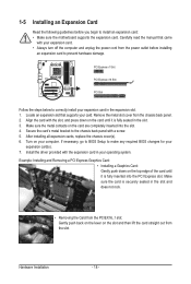
... off the computer and unplug the power cord from the slot. Secure the card's metal bracket to install an expansion card: • Make sure the motherboard supports the expansion card. Remove the metal slot cover from the PCIEX16_1 slot: Gently push back on the lever on the card are completely inserted...
... off the computer and unplug the power cord from the slot. Secure the card's metal bracket to install an expansion card: • Make sure the motherboard supports the expansion card. Remove the metal slot cover from the PCIEX16_1 slot: Gently push back on the lever on the card are completely inserted...
Manual
Page 19
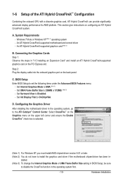
...with a discrete graphics card, ATI Hybrid CrossFireX can provide significantly advanced display performance for AMD platform. An ATI Hybrid CrossFireX-supported motherboard and correct driver - C. D. Hardware Installation Select CrossFire™ on the Graphics menu on the PCI Express slot. Connecting ...- System Requirements - Set Surround View to OnChipVGA. Set Internal Graphics Mode to install the graphics card driver if the motherboard chipset driver has been in "1-5 Installing an Expansion Card" and install an ATI Hybrid CrossFireX-supported graphics card on the ...
...with a discrete graphics card, ATI Hybrid CrossFireX can provide significantly advanced display performance for AMD platform. An ATI Hybrid CrossFireX-supported motherboard and correct driver - C. D. Hardware Installation Select CrossFire™ on the Graphics menu on the PCI Express slot. Connecting ...- System Requirements - Set Surround View to OnChipVGA. Set Internal Graphics Mode to install the graphics card driver if the motherboard chipset driver has been in "1-5 Installing an Expansion Card" and install an ATI Hybrid CrossFireX-supported graphics card on the ...
Manual
Page 21
Dual Display Configurations: This motherboard provides three ports for an IEEE 1394a device. Use this feature, ensure that supports digital optical audio. RJ-45 LAN Port The Gigabit Ethernet LAN ... Setup: At least 256 MB of UMA Frame Buffer Size (refer to an external audio system that your device and then remove it from the motherboard. • When removing the cable, pull it side to side to a back panel connector, first remove the cable from the connector. Use the port to...
Dual Display Configurations: This motherboard provides three ports for an IEEE 1394a device. Use this feature, ensure that supports digital optical audio. RJ-45 LAN Port The Gigabit Ethernet LAN ... Setup: At least 256 MB of UMA Frame Buffer Size (refer to an external audio system that your device and then remove it from the motherboard. • When removing the cable, pull it side to side to a back panel connector, first remove the cable from the connector. Use the port to...
Manual
Page 23
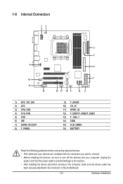
... devices and your devices are compliant with the connectors you wish to connect. • Before installing the devices, be sure to the connector on the motherboard. - 23 - Hardware Installation 1-8 Internal Connectors 13 9 10 11 14 1) ATX_12V_2X4 2) ATX 3) CPU_FAN 4) SYS_FAN 5) FDD 6) IDE 7) SATA2_0/1/2/3/4 8) F_PANEL 2 5 6 7 15 13 16 4 12 8 9) F_AUDIO 10) CD_IN 11...
... devices and your devices are compliant with the connectors you wish to connect. • Before installing the devices, be sure to the connector on the motherboard. - 23 - Hardware Installation 1-8 Internal Connectors 13 9 10 11 14 1) ATX_12V_2X4 2) ATX 3) CPU_FAN 4) SYS_FAN 5) FDD 6) IDE 7) SATA2_0/1/2/3/4 8) F_PANEL 2 5 6 7 15 13 16 4 12 8 9) F_AUDIO 10) CD_IN 11...
Manual
Page 24
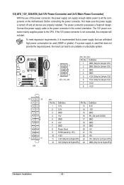
..., the result can supply enough stable power to all devices are properly installed. If a power supply is turned off and all the components on the motherboard. Connect the power supply cable to the CPU.
..., the result can supply enough stable power to all devices are properly installed. If a power supply is turned off and all the components on the motherboard. Connect the power supply cable to the CPU.

Manual
Page 25
... that a system fan be sure to locate pin 1 of floppy disk drives supported are designed with fan speed control design. The motherboard supports CPU fan speed control, which requires the use of different color. CPU_FAN: Pin No. Overheating may hang. • These ... The black connector wire is used to prevent your CPU, North Bridge and system from overheating. Hardware Installation 3/4) CPU_FAN/SYS_FAN (Fan Headers) The motherboard has a 4-pin CPU fan header (CPU_FAN)and a 4-pin system fan header(SYS_FAN). Each fan header supplies a +12V power voltage and possesses...
... that a system fan be sure to locate pin 1 of floppy disk drives supported are designed with fan speed control design. The motherboard supports CPU fan speed control, which requires the use of different color. CPU_FAN: Pin No. Overheating may hang. • These ... The black connector wire is used to prevent your CPU, North Bridge and system from overheating. Hardware Installation 3/4) CPU_FAN/SYS_FAN (Fan Headers) The motherboard has a 4-pin CPU fan header (CPU_FAN)and a 4-pin system fan header(SYS_FAN). Each fan header supplies a +12V power voltage and possesses...


