Manual
Page 4
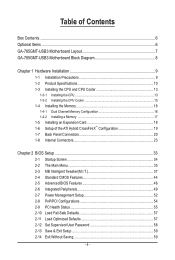
Table of Contents Box Contents...6 Optional Items...6 GA-785GMT-USB3 Motherboard Layout 7 GA-785GMT-USB3 Motherboard Block Diagram 8 Chapter 1 Hardware Installation 9 1-1 Installation Precautions 9 1-2 Product Specifications 10 1-3 Installing the CPU and CPU Cooler 13 1-3-1 Installing the CPU 13 1-3-2 Installing the CPU Cooler 15 1-4 Installing the Memory 16 1-4-1 Dual Channel Memory Configuration 16 1-4-2 Installing a Memory 17 1-5 Installing an Expansion Card 18 1-6 Setup...
Table of Contents Box Contents...6 Optional Items...6 GA-785GMT-USB3 Motherboard Layout 7 GA-785GMT-USB3 Motherboard Block Diagram 8 Chapter 1 Hardware Installation 9 1-1 Installation Precautions 9 1-2 Product Specifications 10 1-3 Installing the CPU and CPU Cooler 13 1-3-1 Installing the CPU 13 1-3-2 Installing the CPU Cooler 15 1-4 Installing the Memory 16 1-4-1 Dual Channel Memory Configuration 16 1-4-2 Installing a Memory 17 1-5 Installing an Expansion Card 18 1-6 Setup...
Manual
Page 8
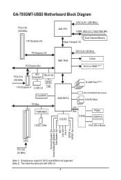
GA-785GMT-USB3 Motherboard Block Diagram PCIe CLK (100 MHz) 1 PCI Express x16 CPU CLK+/- (200 MHz) AM3 CPU DDR3 1800 (O.C.)/1333/1066 MHz Dual Channel Memory Hyper Transport 3.0 PCI Express x16 GFX CLK (100 MHz) PCI Express Bus PCIe CLK (100 MHz) x1 NEC RTL8111D D720200F1 RJ45 1 PCI Express x1 2 USB 3.0 ...
GA-785GMT-USB3 Motherboard Block Diagram PCIe CLK (100 MHz) 1 PCI Express x16 CPU CLK+/- (200 MHz) AM3 CPU DDR3 1800 (O.C.)/1333/1066 MHz Dual Channel Memory Hyper Transport 3.0 PCI Express x16 GFX CLK (100 MHz) PCI Express Bus PCIe CLK (100 MHz) x1 NEC RTL8111D D720200F1 RJ45 1 PCI Express x1 2 USB 3.0 ...
Manual
Page 9
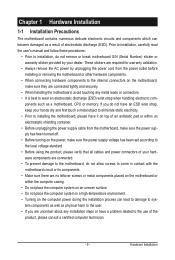
... components. • When connecting hardware components to the internal connectors on the computer power during the installation process can become damaged as a motherboard, CPU or memory. Chapter 1 Hardware Installation 1-1 Installation Precautions The motherboard contains numerous delicate electronic circuits and components which can lead to damage to system components as well as...
... components. • When connecting hardware components to the internal connectors on the computer power during the installation process can become damaged as a motherboard, CPU or memory. Chapter 1 Hardware Installation 1-1 Installation Precautions The motherboard contains numerous delicate electronic circuits and components which can lead to damage to system components as well as...
Manual
Page 10
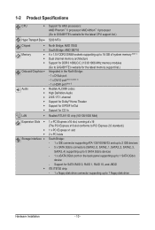
...Phenom™ II processor/ AMD Athlon™ II processor (Go to GIGABYTE's website for the latest CPU support list.) Hyper Transport Bus 5200 MT/s Chipset Memory Onboard Graphics Audio ... SB710 4 x 1.5V DDR3 DIMM sockets supporting up to 16 GB of system memory (Note 1) Dual channel memory architecture Support for DDR3 1800(O.C.)/1333/1066 MHz memory modules (Go to GIGABYTE's website for the latest memory support list.) Integrated in the North Bridge: - 1 x D-Sub port - ...
...Phenom™ II processor/ AMD Athlon™ II processor (Go to GIGABYTE's website for the latest CPU support list.) Hyper Transport Bus 5200 MT/s Chipset Memory Onboard Graphics Audio ... SB710 4 x 1.5V DDR3 DIMM sockets supporting up to 16 GB of system memory (Note 1) Dual channel memory architecture Support for DDR3 1800(O.C.)/1333/1066 MHz memory modules (Go to GIGABYTE's website for the latest memory support list.) Integrated in the North Bridge: - 1 x D-Sub port - ...

Manual
Page 12
... w Micro ATX Form Factor; 24.3cm x 24.3cm (Note 1) Due to Windows 32-bit operating system limitation, when more than 4 GB of physical memory is installed, the actual memory size displayed will be less than 4 GB. (Note 2) The DVI-D port does not support D-Sub connection by adapter. (Note 3) Simultaneous output for DVI...
... w Micro ATX Form Factor; 24.3cm x 24.3cm (Note 1) Due to Windows 32-bit operating system limitation, when more than 4 GB of physical memory is installed, the actual memory size displayed will be less than 4 GB. (Note 2) The DVI-D port does not support D-Sub connection by adapter. (Note 3) Simultaneous output for DVI...
Manual
Page 13
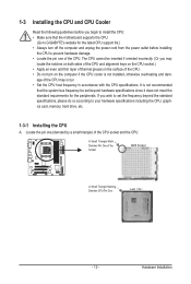
...incorrectly. (Or you wish to set beyond the standard specifications, please do so according to your hardware specifications including the CPU, graphics card, memory, hard drive, etc. 1-3-1 Installing the CPU A. The CPU cannot be set the frequency beyond hardware specifications since it does not meet ... list.) • Always turn on the computer if the CPU cooler is not recommended that the motherboard supports the CPU. (Go to GIGABYTE's website for the peripherals. Hardware Installation A Small Triangle Mark Denotes Pin One of the CPU socket and the CPU. It is not installed...
...incorrectly. (Or you wish to set beyond the standard specifications, please do so according to your hardware specifications including the CPU, graphics card, memory, hard drive, etc. 1-3-1 Installing the CPU A. The CPU cannot be set the frequency beyond hardware specifications since it does not meet ... list.) • Always turn on the computer if the CPU cooler is not recommended that the motherboard supports the CPU. (Go to GIGABYTE's website for the peripherals. Hardware Installation A Small Triangle Mark Denotes Pin One of the CPU socket and the CPU. It is not installed...
Manual
Page 16
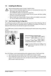
...Always turn off the computer and unplug the power cord from the power outlet before installing the memory to prevent hardware damage. • Memory modules have a foolproof design. A memory module can be enabled if only one direction. DS/SS DS/SS Four Modules DS/SS DS... four memory modules, it is recommended that memory of the memory. It is installed, the BIOS will double the original memory bandwidth. Enabling Dual Channel memory mode will automatically detect the specifications and capacity of the same capacity, brand, speed, and chips be used . (Go to GIGABYTE's website...
...Always turn off the computer and unplug the power cord from the power outlet before installing the memory to prevent hardware damage. • Memory modules have a foolproof design. A memory module can be enabled if only one direction. DS/SS DS/SS Four Modules DS/SS DS... four memory modules, it is recommended that memory of the memory. It is installed, the BIOS will double the original memory bandwidth. Enabling Dual Channel memory mode will automatically detect the specifications and capacity of the same capacity, brand, speed, and chips be used . (Go to GIGABYTE's website...

Manual
Page 17
...orientation of the socket will snap into the memory socket. Hardware Installation Step 2: The clips at both ends of the memory module. Follow the steps below to correctly install your fingers on the memory and insert it can only fit in the memory sockets. As indicated in the picture on... the socket. Notch DDR3 DIMM A DDR3 memory module has a notch, so it vertically into place when the memory module is securely inserted. - 17 - Place the memory module on the left, place your memory modules in one direction. DDR3 and DDR2 DIMMs are not compatible to...
...orientation of the socket will snap into the memory socket. Hardware Installation Step 2: The clips at both ends of the memory module. Follow the steps below to correctly install your fingers on the memory and insert it can only fit in the memory sockets. As indicated in the picture on... the socket. Notch DDR3 DIMM A DDR3 memory module has a notch, so it vertically into place when the memory module is securely inserted. - 17 - Place the memory module on the left, place your memory modules in one direction. DDR3 and DDR2 DIMMs are not compatible to...
Manual
Page 21
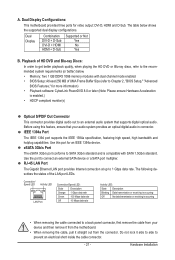
... an optical digital audio in connector. Dual Display Configurations: This motherboard provides three ports for an IEEE 1394a device. The table below . • Memory: Two 1 GB DDR3 1066 memory modules with SATA 1.5Gb/s standard. Use this feature, ensure that supports digital optical audio. Dual Display Combination DVI-D + D-Sub DVI-D + HDMI HDMI + D-Sub...
... an optical digital audio in connector. Dual Display Configurations: This motherboard provides three ports for an IEEE 1394a device. The table below . • Memory: Two 1 GB DDR3 1066 memory modules with SATA 1.5Gb/s standard. Use this feature, ensure that supports digital optical audio. Dual Display Combination DVI-D + D-Sub DVI-D + HDMI HDMI + D-Sub...

Manual
Page 36
... settings. First enter the profile name (to erase the default profile name, use this function to load the BIOS settings from BIOS If your CPU, memory, etc. Standard CMOS Features Use this menu to configure the system time and date, hard drive types, floppy disk drive types, and the type...
... settings. First enter the profile name (to erase the default profile name, use this function to load the BIOS settings from BIOS If your CPU, memory, etc. Standard CMOS Features Use this menu to configure the system time and date, hard drive types, floppy disk drive types, and the type...
Manual
Page 37
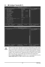
...Auto to optimize the system voltage settings. - 37 - CPU Host Clock Control x CPU Frequency(MHz) PCIE Clock(MHz) HT Link Width HT Link Frequency Set Memory Clock x Memory Clock } DRAM Configuration ******** System Voltage Optimized ******** System Voltage Control x DDR3 Voltage Control x NorthBridge Volt Control x SouthBridge Volt Control x CPU NB VID Control... settings to prevent system instability or other unexpected results. (Inadequately altering the settings may result in damage to CPU, chipset, or memory and reduce the useful life of these components.
...Auto to optimize the system voltage settings. - 37 - CPU Host Clock Control x CPU Frequency(MHz) PCIE Clock(MHz) HT Link Width HT Link Frequency Set Memory Clock x Memory Clock } DRAM Configuration ******** System Voltage Optimized ******** System Voltage Control x DDR3 Voltage Control x NorthBridge Volt Control x SouthBridge Volt Control x CPU NB VID Control... settings to prevent system instability or other unexpected results. (Inadequately altering the settings may result in damage to CPU, chipset, or memory and reduce the useful life of these components.
Manual
Page 39
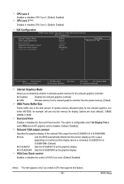
... automatically determines the primary display port for display. Surround View Enables or disables the Surround View function. BIOS Setup UMA Allocates memory for the onboard graphics controller from the D-SUB/DVI-D or D-SUB/HDMI. VGA Core Clock control Enables or disables the control... of VGA Core clock. (Default: Disabled) (Note) This item appears only if you to determine whether to allocate system memory for the onboard graphics controller. CPU core 2 Enables or disables CPU Core 2. (Default: Enabled) CPU core 3 (Note) Enables or disables CPU...
... automatically determines the primary display port for display. Surround View Enables or disables the Surround View function. BIOS Setup UMA Allocates memory for the onboard graphics controller from the D-SUB/DVI-D or D-SUB/HDMI. VGA Core Clock control Enables or disables the control... of VGA Core clock. (Default: Disabled) (Note) This item appears only if you to determine whether to allocate system memory for the onboard graphics controller. CPU core 2 Enables or disables CPU Core 2. (Default: Enabled) CPU core 3 (Note) Enables or disables CPU...
Manual
Page 40
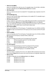
...(MHz) Allows you to 200 MHz. The adjustable range is from 100 MHz to manually set in accordance with the CPU specifications. X4.00 Sets Memory Clock to alter the clock ratio for automated system reboot, or clear the CMOS values to reset the board to 16 bit. CPU Clock Ratio... Allows you to X4.00. The adjustable range is from 200 MHz to X8.00. X8.00 Sets Memory Clock to 500 MHz. CPU NorthBridge Freq. CPU Host Clock Control Enables or disables the control of CPU host clock. Auto (default) allows the BIOS...
...(MHz) Allows you to 200 MHz. The adjustable range is from 100 MHz to manually set in accordance with the CPU specifications. X4.00 Sets Memory Clock to alter the clock ratio for automated system reboot, or clear the CMOS values to reset the board to 16 bit. CPU Clock Ratio... Allows you to X4.00. The adjustable range is from 200 MHz to X8.00. X8.00 Sets Memory Clock to 500 MHz. CPU NorthBridge Freq. CPU Host Clock Control Enables or disables the control of CPU host clock. Auto (default) allows the BIOS...
Manual
Page 41
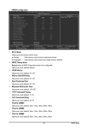
Unganged Sets memory control mode to two single-channel. (Default) DDR3 Timing Items Manual allows all DDR3 Timing items below to CAS R/W Delay Options are: Auto (default), 5T~... Active Time Options are: Auto (default), 15T~30T. 1T/2T Command Timing Options are : Auto (default), 90ns, 110ns, 160ns, 300ns, 350ns. Ganged Sets memory control mode to set memory control mode. Trfc2 for DIMM1 Options are : Auto (default), 5T~12T. Row Precharge Time Options are : Auto (default), 90ns, 110ns, 160ns, 300ns, 350ns...
Unganged Sets memory control mode to two single-channel. (Default) DDR3 Timing Items Manual allows all DDR3 Timing items below to CAS R/W Delay Options are: Auto (default), 5T~... Active Time Options are: Auto (default), 15T~30T. 1T/2T Command Timing Options are : Auto (default), 90ns, 110ns, 160ns, 300ns, 350ns. Ganged Sets memory control mode to set memory control mode. Trfc2 for DIMM1 Options are : Auto (default), 5T~12T. Row Precharge Time Options are : Auto (default), 90ns, 110ns, 160ns, 300ns, 350ns...
Manual
Page 42
.... (Default: Normal) Note: Increasing CPU voltage may result in damage to your CPU or reduce the useful life of the memory to increase memory performance and stability. (Default: Enabled) ******** System Voltage Optimized ******** System Voltage Control Determines whether to set the North Bridge voltage.... Write Recovery Time Options are : Auto (default), 4T~7T. Bank Interleaving Enables or disables memory bank interleaving. The adjustable range is from +0.1V to +0.3V. NorthBridge Volt Control Allows you to manually set the system voltages as...
.... (Default: Normal) Note: Increasing CPU voltage may result in damage to your CPU or reduce the useful life of the memory to increase memory performance and stability. (Default: Enabled) ******** System Voltage Optimized ******** System Voltage Control Determines whether to set the North Bridge voltage.... Write Recovery Time Options are : Auto (default), 4T~7T. Bank Interleaving Enables or disables memory bank interleaving. The adjustable range is from +0.1V to +0.3V. NorthBridge Volt Control Allows you to manually set the system voltages as...
Manual
Page 44
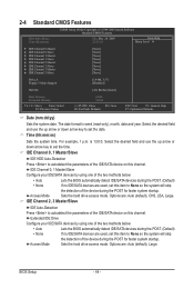
... 3 Master } IDE Channel 3 Slave [None] [None] [None] [None] [None] [None] [None] [None] Drive A Floppy 3 Mode Support [1.44M, 3.5"] [Disabled] Halt On [All, But Keyboard] Base Memory Extended Memory 640K 382M Move Enter: Select F5: Previous Values +/-/PU/PD: Value F10: Save F6: Fail-Safe Defaults ESC: Exit F1: General Help F7: Optimized Defaults...
... 3 Master } IDE Channel 3 Slave [None] [None] [None] [None] [None] [None] [None] [None] Drive A Floppy 3 Mode Support [1.44M, 3.5"] [Disabled] Halt On [All, But Keyboard] Base Memory Extended Memory 640K 382M Move Enter: Select F5: Previous Values +/-/PU/PD: Value F10: Save F6: Fail-Safe Defaults ESC: Exit F1: General Help F7: Optimized Defaults...
Manual
Page 45
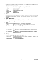
...of sectors. Precomp Write precompensation cylinder. If you wish to enter the parameters manually, refer to the information on the hard drive. Memory These fields are read-only and are : Disabled (default), Drive A. BIOS Setup Sector Number of the currently installed hard drive. ... disk drive. Drive A Allows you to None. Halt On Allows you to select the type of cylinders. Base Memory Also called conventional memory. Head Number of extended memory. - 45 - Floppy 3 Mode Support Allows you to determine whether the system will not stop for any error....
...of sectors. Precomp Write precompensation cylinder. If you wish to enter the parameters manually, refer to the information on the hard drive. Memory These fields are read-only and are : Disabled (default), Drive A. BIOS Setup Sector Number of the currently installed hard drive. ... disk drive. Drive A Allows you to None. Halt On Allows you to select the type of cylinders. Base Memory Also called conventional memory. Head Number of extended memory. - 45 - Floppy 3 Mode Support Allows you to determine whether the system will not stop for any error....
Manual
Page 46
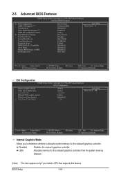
... Third Boot Device Password Check HDD S.M.A.R.T. Disabled Disables the onboard graphics controller. Capability Away Mode Backup BIOS Image to allocate system memory for the onboard graphics controller from the system memory. (Default) (Note) This item appears only if you to determine whether to HDD Init Display First [Press Enter] [Software ...-Safe Defaults ESC: Exit F1: General Help F7: Optimized Defaults Internal Graphics Mode Allows you install a CPU that supports this feature. UMA Allocates memory for the onboard graphics controller.
... Third Boot Device Password Check HDD S.M.A.R.T. Disabled Disables the onboard graphics controller. Capability Away Mode Backup BIOS Image to allocate system memory for the onboard graphics controller from the system memory. (Default) (Note) This item appears only if you to determine whether to HDD Init Display First [Press Enter] [Software ...-Safe Defaults ESC: Exit F1: General Help F7: Optimized Defaults Internal Graphics Mode Allows you install a CPU that supports this feature. UMA Allocates memory for the onboard graphics controller.

Manual
Page 47
...Enables or disables the control of VGA Core clock. (Default: Disabled) VGA Core Clock(MHz) Allows you install a CPU that supports this memory for output, depending on the list. This item is configurable only if the VGA Core Clock control option is enabled. This option is ...loading the operating system from the D-SUB/DVI-D or D-SUB/HDMI. UMA Frame Buffer Size Frame buffer size is the total amount of system memory allocated solely for example, will be reduced during system halt state to decrease power consumption. (Default: Disabled) Virtualization Virtualization allows a platform to...
...Enables or disables the control of VGA Core clock. (Default: Disabled) VGA Core Clock(MHz) Allows you install a CPU that supports this memory for output, depending on the list. This item is configurable only if the VGA Core Clock control option is enabled. This option is ...loading the operating system from the D-SUB/DVI-D or D-SUB/HDMI. UMA Frame Buffer Size Frame buffer size is the total amount of system memory allocated solely for example, will be reduced during system halt state to decrease power consumption. (Default: Disabled) Virtualization Virtualization allows a platform to...
Manual
Page 53
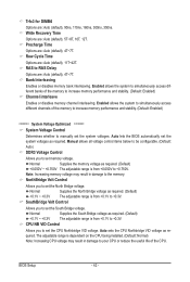
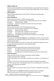
... prompted for Windows Vista operating system. (Default: Enabled) Power On By Mouse Allows the system to turn on the system, enter the password and press . Memory The system returns to turn on the system. Disabled Disables this function. (Default) Password Set a password with up event. Power-On by Alarm Determines whether...
... prompted for Windows Vista operating system. (Default: Enabled) Power On By Mouse Allows the system to turn on the system, enter the password and press . Memory The system returns to turn on the system. Disabled Disables this function. (Default) Password Set a password with up event. Power-On by Alarm Determines whether...


