Manual
Page 3
... In order to the specifications and features in the use GIGABYTE's unique features, read or download the information on/from the Support&Downloads\Motherboard\Technology Guide page on how to their respective owners. For product-related information, check on our website at: http://www.gigabyte.com.tw Identifying Your Motherboard Revision The revision number on your motherboard revision before updating motherboard BIOS, drivers, or when looking...
... In order to the specifications and features in the use GIGABYTE's unique features, read or download the information on/from the Support&Downloads\Motherboard\Technology Guide page on how to their respective owners. For product-related information, check on our website at: http://www.gigabyte.com.tw Identifying Your Motherboard Revision The revision number on your motherboard revision before updating motherboard BIOS, drivers, or when looking...
Manual
Page 4
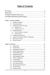
... Motherboard Layout 7 GA-785GMT-USB3 Motherboard Block Diagram 8 Chapter 1 Hardware Installation 9 1-1 Installation Precautions 9 1-2 Product Specifications 10 1-3 Installing the CPU and CPU Cooler 13 1-3-1 Installing the CPU 13 1-3-2 Installing the CPU Cooler 15 1-4 Installing the Memory 16 1-4-1 Dual Channel Memory Configuration 16 1-4-2 Installing a Memory 17 1-5 Installing an Expansion Card 18 1-6 Setup of the ATI Hybrid CrossFireX™ Configuration 19 1-7 Back Panel Connectors 20 1-8 Internal Connectors 23 Chapter 2 BIOS Setup 33 2-1 Startup Screen 34 2-2 The Main Menu...
... Motherboard Layout 7 GA-785GMT-USB3 Motherboard Block Diagram 8 Chapter 1 Hardware Installation 9 1-1 Installation Precautions 9 1-2 Product Specifications 10 1-3 Installing the CPU and CPU Cooler 13 1-3-1 Installing the CPU 13 1-3-2 Installing the CPU Cooler 15 1-4 Installing the Memory 16 1-4-1 Dual Channel Memory Configuration 16 1-4-2 Installing a Memory 17 1-5 Installing an Expansion Card 18 1-6 Setup of the ATI Hybrid CrossFireX™ Configuration 19 1-7 Back Panel Connectors 20 1-8 Internal Connectors 23 Chapter 2 BIOS Setup 33 2-1 Startup Screen 34 2-2 The Main Menu...
Manual
Page 8
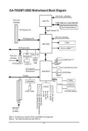
GA-785GMT-USB3 Motherboard Block Diagram PCIe CLK (100 MHz) 1 PCI Express x16 CPU CLK+/- (200 MHz) AM3 CPU DDR3 1800 (O.C.)/1333/1066 MHz Dual Channel Memory Hyper Transport 3.0 PCI Express x16 GFX CLK (100 MHz) PCI Express Bus PCIe CLK (100 MHz) x1 NEC RTL8111D D720200F1 RJ45 1 PCI Express x1 2 USB 3.0 LAN Dual BIOS PCI Bus TSB43AB23 AMD 785G AMD SB710 CODEC D-Sub DVI-D or HDMI (Note 1) 12 USB Ports (Note 2) ATA-133/100/66/33 IDE Channel 6 SATA 3Gb/s LPC Bus IT8720 Floppy COM Port 2 IEEE 1394a...
GA-785GMT-USB3 Motherboard Block Diagram PCIe CLK (100 MHz) 1 PCI Express x16 CPU CLK+/- (200 MHz) AM3 CPU DDR3 1800 (O.C.)/1333/1066 MHz Dual Channel Memory Hyper Transport 3.0 PCI Express x16 GFX CLK (100 MHz) PCI Express Bus PCIe CLK (100 MHz) x1 NEC RTL8111D D720200F1 RJ45 1 PCI Express x1 2 USB 3.0 LAN Dual BIOS PCI Bus TSB43AB23 AMD 785G AMD SB710 CODEC D-Sub DVI-D or HDMI (Note 1) 12 USB Ports (Note 2) ATA-133/100/66/33 IDE Channel 6 SATA 3Gb/s LPC Bus IT8720 Floppy COM Port 2 IEEE 1394a...
Manual
Page 10
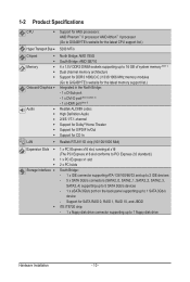
... up to 2 IDE devices - 5 x SATA 3Gb/s connectors (SATA2_0, SATA2_1, SATA2_2, SATA2_3, SATA2_4) supporting up to 5 SATA 3Gb/s devices - 1 x eSATA 3Gb/s port on the back panel supporting up to 1 SATA 3Gb/s device - 1-2 Product Specifications CPU Support for AM3 processors: AMD Phenom™ II processor/ AMD Athlon™ II processor (Go to GIGABYTE's website for the latest CPU support list.) Hyper Transport Bus 5200 MT/s Chipset Memory Onboard Graphics Audio ...
... up to 2 IDE devices - 5 x SATA 3Gb/s connectors (SATA2_0, SATA2_1, SATA2_2, SATA2_3, SATA2_4) supporting up to 5 SATA 3Gb/s devices - 1 x eSATA 3Gb/s port on the back panel supporting up to 1 SATA 3Gb/s device - 1-2 Product Specifications CPU Support for AM3 processors: AMD Phenom™ II processor/ AMD Athlon™ II processor (Go to GIGABYTE's website for the latest CPU support list.) Hyper Transport Bus 5200 MT/s Chipset Memory Onboard Graphics Audio ...
Manual
Page 19
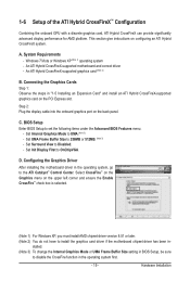
... 2: Plug the display cable into the onboard graphics port on configuring an ATI Hybrid CrossFireX system. Set Internal Graphics Mode to set the following items under the Advanced BIOS Features menu: - Select CrossFire™ on the Graphics menu on the PCI Express slot. Hardware Installation Windows 7/Vista or Windows XP (Note 1) operating system - BIOS Setup Enter BIOS Setup to UMA.(Note 3) - Set Surround View to 256MB or 512MB. (Note 3) - D. stalled. (Note 3) To change the Internal Graphics Mode or UMA Frame Buffer Size setting in BIOS Setup...
... 2: Plug the display cable into the onboard graphics port on configuring an ATI Hybrid CrossFireX system. Set Internal Graphics Mode to set the following items under the Advanced BIOS Features menu: - Select CrossFire™ on the Graphics menu on the PCI Express slot. Hardware Installation Windows 7/Vista or Windows XP (Note 1) operating system - BIOS Setup Enter BIOS Setup to UMA.(Note 3) - Set Surround View to 256MB or 512MB. (Note 3) - D. stalled. (Note 3) To change the Internal Graphics Mode or UMA Frame Buffer Size setting in BIOS Setup...

Manual
Page 25
... installed inside the chassis. For purchasing the optional floppy disk drive cable, please contact the local dealer. 34 33 2 1 - 25 - Most fans are designed with fan speed control design. The black connector wire is used to connect a floppy disk drive. For optimum heat dissipation, it in damage to locate pin 1 of floppy disk drives supported are not configuration jumper blocks. Overheating may result in the correct orientation. 3/4) CPU_FAN/SYS_FAN (Fan Headers) The motherboard has a 4-pin CPU fan header (CPU_FAN)and a 4-pin system fan header(SYS_FAN). A red power...
... installed inside the chassis. For purchasing the optional floppy disk drive cable, please contact the local dealer. 34 33 2 1 - 25 - Most fans are designed with fan speed control design. The black connector wire is used to connect a floppy disk drive. For optimum heat dissipation, it in damage to locate pin 1 of floppy disk drives supported are not configuration jumper blocks. Overheating may result in the correct orientation. 3/4) CPU_FAN/SYS_FAN (Fan Headers) The motherboard has a 4-pin CPU fan header (CPU_FAN)and a 4-pin system fan header(SYS_FAN). A red power...
Manual
Page 31
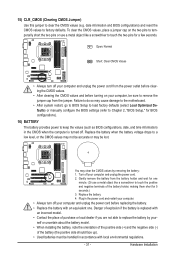
... BIOS configurations) and reset the CMOS values to clear the CMOS values (e.g. To clear the CMOS values, place a jumper cap on your computer and unplug the power cord. 2. Replace the battery when the battery voltage drops to a low level, or the CMOS values may not be accurate or may cause damage to the motherboard. • After system restart, go to BIOS Setup to load factory defaults (select Load Optimized Defaults) or manually configure the BIOS settings...
... BIOS configurations) and reset the CMOS values to clear the CMOS values (e.g. To clear the CMOS values, place a jumper cap on your computer and unplug the power cord. 2. Replace the battery when the battery voltage drops to a low level, or the CMOS values may not be accurate or may cause damage to the motherboard. • After system restart, go to BIOS Setup to load factory defaults (select Load Optimized Defaults) or manually configure the BIOS settings...
Manual
Page 34
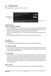
... access the Q-Flash utility in Boot Menu. BIOS Setup - 34 - The system will still be used for the SATA connectors. For more information, refer to Chapter 4, "Xpress Recovery2." : BOOT MENU Boot Menu allows you want to change the first boot device setting as needed. : Q-FLASH Press the key to access the Q-Flash utility directly without entering BIOS Setup. In Boot Menu, use the up hard drive data using the driver disk, the key can access Boot Menu again to change it to AHCI mode and enable hot plug functionality for subsequent access to continue IDE mode...
... access the Q-Flash utility in Boot Menu. BIOS Setup - 34 - The system will still be used for the SATA connectors. For more information, refer to Chapter 4, "Xpress Recovery2." : BOOT MENU Boot Menu allows you want to change the first boot device setting as needed. : Q-FLASH Press the key to access the Q-Flash utility directly without entering BIOS Setup. In Boot Menu, use the up hard drive data using the driver disk, the key can access Boot Menu again to change it to AHCI mode and enable hot plug functionality for subsequent access to continue IDE mode...

Manual
Page 36
... clock, frequency and voltages of your CPU, memory, etc. Standard CMOS Features Use this menu to configure the system time and date, hard drive types, floppy disk drive types, and the type of errors that stop the system boot, etc. Advanced BIOS Features Use this menu to configure the device boot order, advanced features available on the CPU, and the primary display adapter. Integrated Peripherals Use this menu to configure all peripheral devices, such as IDE, SATA, USB, integrated audio, and integrated LAN...
... clock, frequency and voltages of your CPU, memory, etc. Standard CMOS Features Use this menu to configure the system time and date, hard drive types, floppy disk drive types, and the type of errors that stop the system boot, etc. Advanced BIOS Features Use this menu to configure the device boot order, advanced features available on the CPU, and the primary display adapter. Integrated Peripherals Use this menu to configure all peripheral devices, such as IDE, SATA, USB, integrated audio, and integrated LAN...
Manual
Page 39
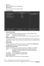
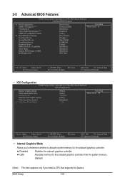
...HDMI as the graphics display. UMA Allocates memory for the onboard graphics controller from the D-SUB/DVI-D or D-SUB/HDMI. CPU core 2 Enables or disables CPU Core 2. (Default: Enabled) CPU core 3 (Note) Enables or disables CPU Core 3. (Default: Enabled) IGX Configuration CMOS Setup Utility-Copyright (C) 1984-2009 Award Software IGX Configuration Internal Graphics Mode UMA Frame Buffer Size x Surround View Onboard VGA output connect VGA Core Clock control x VGA Core Clock(MHz) [UMA] [Auto] Disabled [Auto] [Disabled] 500 Item Help Menu Level Move Enter...
...HDMI as the graphics display. UMA Allocates memory for the onboard graphics controller from the D-SUB/DVI-D or D-SUB/HDMI. CPU core 2 Enables or disables CPU Core 2. (Default: Enabled) CPU core 3 (Note) Enables or disables CPU Core 3. (Default: Enabled) IGX Configuration CMOS Setup Utility-Copyright (C) 1984-2009 Award Software IGX Configuration Internal Graphics Mode UMA Frame Buffer Size x Surround View Onboard VGA output connect VGA Core Clock control x VGA Core Clock(MHz) [UMA] [Auto] Disabled [Auto] [Disabled] 500 Item Help Menu Level Move Enter...
Manual
Page 46
...HDD Init Display First [Press Enter] [Software SMI] [Disabled] [Enabled] [Auto] [Press Enter] [Floppy] [Hard Disk] [CDROM] [Setup] [Disabled] [Disabled] [Disabled] [PCI Slot] Item Help Menu Level Move Enter: Select F5: Previous Values +/-/PU/PD: Value F10: Save F6: Fail-Safe Defaults ESC: Exit F1: General Help F7: Optimized Defaults IGX Configuration CMOS Setup Utility-Copyright (C) 1984-2009 Award Software IGX Configuration Internal Graphics Mode UMA Frame Buffer Size x Surround View Onboard VGA output connect VGA Core Clock control x VGA Core Clock...
...HDD Init Display First [Press Enter] [Software SMI] [Disabled] [Enabled] [Auto] [Press Enter] [Floppy] [Hard Disk] [CDROM] [Setup] [Disabled] [Disabled] [Disabled] [PCI Slot] Item Help Menu Level Move Enter: Select F5: Previous Values +/-/PU/PD: Value F10: Save F6: Fail-Safe Defaults ESC: Exit F1: General Help F7: Optimized Defaults IGX Configuration CMOS Setup Utility-Copyright (C) 1984-2009 Award Software IGX Configuration Internal Graphics Mode UMA Frame Buffer Size x Surround View Onboard VGA output connect VGA Core Clock control x VGA Core Clock...

Manual
Page 47
... list. BIOS Setup D-SUB/HDMI Sets the D-SUB/HDMI as the graphics display. This option is configurable only if an ATI graphics card is the total amount of system memory allocated solely for example, will be reduced during system halt state to decrease power consumption. (Default: Disabled) Virtualization Virtualization allows a platform to 2000 MHz. This item is configurable only if the VGA Core Clock control option is from the installed hard drives. Press to manually set the VGA Core clock. AMD C1E Support (Note) Enables...
... list. BIOS Setup D-SUB/HDMI Sets the D-SUB/HDMI as the graphics display. This option is configurable only if an ATI graphics card is the total amount of system memory allocated solely for example, will be reduced during system halt state to decrease power consumption. (Default: Disabled) Virtualization Virtualization allows a platform to 2000 MHz. This item is configurable only if the VGA Core Clock control option is from the installed hard drives. Press to manually set the VGA Core clock. AMD C1E Support (Note) Enables...
Manual
Page 48
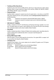
... hardware monitor utility is required every time the system boots, or only when you enter BIOS Setup. HDD S.M.A.R.T. BIOS Setup - 48 - Away Mode allows the system to report read/write errors of the monitor display from the available devices. Options are: Floppy, LS120, Hard Disk, CDROM, ZIP, USB-FDD, USB-ZIP, USB-CDROM, USB-HDD, Legacy LAN, Disabled. First/Second/Third Boot Device Specifies the boot order from the installed PCI graphics card, PCI Express graphics card, or the onboard VGA. After configuring this image file. (Default: Disabled) Init Display First Specifies...
... hardware monitor utility is required every time the system boots, or only when you enter BIOS Setup. HDD S.M.A.R.T. BIOS Setup - 48 - Away Mode allows the system to report read/write errors of the monitor display from the available devices. Options are: Floppy, LS120, Hard Disk, CDROM, ZIP, USB-FDD, USB-ZIP, USB-CDROM, USB-HDD, Legacy LAN, Disabled. First/Second/Third Boot Device Specifies the boot order from the installed PCI graphics card, PCI Express graphics card, or the onboard VGA. After configuring this image file. (Default: Disabled) Init Display First Specifies...

Manual
Page 49
...AHCI Configures the SATA controllers to RAID or AHCI. 2-6 Integrated Peripherals CMOS Setup Utility-Copyright (C) 1984-2009 Award Software Integrated Peripherals OnChip SATA Controller OnChip SATA Type x OnChip SATA Port4/5 Type Onboard LAN Function Onboard LAN Boot ROM } SMART LAN Onboard Audio Function Onboard 1394 Function Onboard USB 3.0 Controller OnChip USB Controller USB EHCI Controller USB Keyboard Support USB Mouse Support Legacy USB storage detect Onboard Serial Port 1 [Enabled] [Native IDE] IDE [Enabled] [Disabled] [Press Enter] [Enabled...
...AHCI Configures the SATA controllers to RAID or AHCI. 2-6 Integrated Peripherals CMOS Setup Utility-Copyright (C) 1984-2009 Award Software Integrated Peripherals OnChip SATA Controller OnChip SATA Type x OnChip SATA Port4/5 Type Onboard LAN Function Onboard LAN Boot ROM } SMART LAN Onboard Audio Function Onboard 1394 Function Onboard USB 3.0 Controller OnChip USB Controller USB EHCI Controller USB Keyboard Support USB Mouse Support Legacy USB storage detect Onboard Serial Port 1 [Enabled] [Native IDE] IDE [Enabled] [Disabled] [Press Enter] [Enabled...
Manual
Page 52
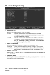
... to RAM) sleep state (default). S3(STR) Enables the system to enter the ACPI S3 (Suspend to be off the computer in MS-DOS mode using the power button. 2-7 Power Management Setup CMOS Setup Utility-Copyright (C) 1984-2009 Award Software Power Management Setup ACPI Suspend Type Soft-Off by Power button USB Wake Up from S3 Modem Ring Resume PME Event Wake Up HPET Support (Note) Power On By Mouse Power On By Keyboard x KB Power ON Password AC Back Function Power-On...
... to RAM) sleep state (default). S3(STR) Enables the system to enter the ACPI S3 (Suspend to be off the computer in MS-DOS mode using the power button. 2-7 Power Management Setup CMOS Setup Utility-Copyright (C) 1984-2009 Award Software Power Management Setup ACPI Suspend Type Soft-Off by Power button USB Wake Up from S3 Modem Ring Resume PME Event Wake Up HPET Support (Note) Power On By Mouse Power On By Keyboard x KB Power ON Password AC Back Function Power-On...
Manual
Page 68
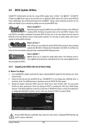
..., users cannot update the backup BIOS manually. Before You Begin 1. During the POST, press the key to enter operating systems like MS-DOS or Window first. Motherboards that matches your computer by either pressing the key during the POST to your floppy disk, USB flash drive, or hard drive. With Q-Flash you to update the system BIOS while in BIOS Setup. site and update the BIOS. From GIGABYTE's website, download the latest compressed BIOS update file that support DualBIOS have two BIOS onboard, a main BIOS...
..., users cannot update the backup BIOS manually. Before You Begin 1. During the POST, press the key to enter operating systems like MS-DOS or Window first. Motherboards that matches your computer by either pressing the key during the POST to your floppy disk, USB flash drive, or hard drive. With Q-Flash you to update the system BIOS while in BIOS Setup. site and update the BIOS. From GIGABYTE's website, download the latest compressed BIOS update file that support DualBIOS have two BIOS onboard, a main BIOS...

Manual
Page 79
... a RAID array in BIOS Setup. Installing SATA hard drive(s) in your power supply to the hard drive. (Note 1) Skip this step if you use two hard drives with identical model and capacity). Then connect the power connector from your computer. Install the SATA RAID/AHCI driver (Note 2) and operating system. Configure SATA controller mode in RAID BIOS. (Note 1) D. Install SATA hard drive(s) in your computer Attach one hard drive. • An empty formatted floppy disk. • Windows Vista/XP setup disk. • Motherboard driver disk. 5-1-1 Configuring the Onboard SATA Controller...
... a RAID array in BIOS Setup. Installing SATA hard drive(s) in your power supply to the hard drive. (Note 1) Skip this step if you use two hard drives with identical model and capacity). Then connect the power connector from your computer. Install the SATA RAID/AHCI driver (Note 2) and operating system. Configure SATA controller mode in RAID BIOS. (Note 1) D. Install SATA hard drive(s) in your computer Attach one hard drive. • An empty formatted floppy disk. • Windows Vista/XP setup disk. • Motherboard driver disk. 5-1-1 Configuring the Onboard SATA Controller...
Manual
Page 85
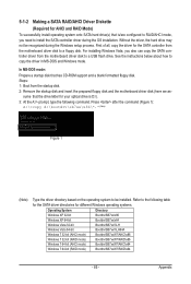
... the motherboard driver disk to install the SATA controller driver during the Windows setup process. Press after the command (Figure 1): A:\>copy d:\bootdrv\sb7xx\x86\*.* (Note) Figure 1 (Note) Type the driver directory based on the operating system to copy the driver in MS-DOS and Windows mode. Refer to a USB flash drive. For installing Windows Vista, you need to a floppy disk. sume that has CD-ROM support and a blank formatted floppy disk. Appendix Without the driver, the hard drive...
... the motherboard driver disk to install the SATA controller driver during the Windows setup process. Press after the command (Figure 1): A:\>copy d:\bootdrv\sb7xx\x86\*.* (Note) Figure 1 (Note) Type the driver directory based on the operating system to copy the driver in MS-DOS and Windows mode. Refer to a USB flash drive. For installing Windows Vista, you need to a floppy disk. sume that has CD-ROM support and a blank formatted floppy disk. Appendix Without the driver, the hard drive...
Manual
Page 87
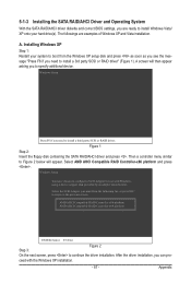
... RAID driver" (Figure 1). Figure 1 Step 2: Insert the floppy disk containing the SATA RAID/AHCI driver and press . Windows Setup You have chosen to Figure 2 below will then appear asking you to install a third party SCSI or RAID driver. A. 5-1-3 Installing the SATA RAID/AHCI Driver and Operating System With the SATA RAID/AHCI driver diskette and correct BIOS settings, you are examples of Windows XP and Vista installation. Then a controller menu similar to configure a SCSI Adapter for use with the Windows XP installation...
... RAID driver" (Figure 1). Figure 1 Step 2: Insert the floppy disk containing the SATA RAID/AHCI driver and press . Windows Setup You have chosen to Figure 2 below will then appear asking you to install a third party SCSI or RAID driver. A. 5-1-3 Installing the SATA RAID/AHCI Driver and Operating System With the SATA RAID/AHCI driver diskette and correct BIOS settings, you are examples of Windows XP and Vista installation. Then a controller menu similar to configure a SCSI Adapter for use with the Windows XP installation...

Manual
Page 99
...install the onboard HD audio driver successfully? (For Windows XP only) A: Step 1: First, make sure the Microsoft UAA Bus Driver for hardware changes. A: The following Award BIOS beep code descriptions may help you identify possible computer problems. (For reference only.) 1 short: System boots successfully 1 long, 3 short: Keyboard error 2 short: CMOS setting error 1 long, 9 short: BIOS ROM error 1 long, 1 short: Memory or motherboard error Continuous long beeps: Graphics card not inserted properly 1 long, 2 short: Monitor or graphics card error Continuous short beeps: Power error...
...install the onboard HD audio driver successfully? (For Windows XP only) A: Step 1: First, make sure the Microsoft UAA Bus Driver for hardware changes. A: The following Award BIOS beep code descriptions may help you identify possible computer problems. (For reference only.) 1 short: System boots successfully 1 long, 3 short: Keyboard error 2 short: CMOS setting error 1 long, 9 short: BIOS ROM error 1 long, 1 short: Memory or motherboard error Continuous long beeps: Graphics card not inserted properly 1 long, 2 short: Monitor or graphics card error Continuous short beeps: Power error...


