Manual
Page 1
GA-785GMT-USB3 AM3 socket motherboard for AMD Phenom™ II processor/ AMD Athlon™ II processor User's Manual Rev. 1001 12ME-785TB3-1001R
GA-785GMT-USB3 AM3 socket motherboard for AMD Phenom™ II processor/ AMD Athlon™ II processor User's Manual Rev. 1001 12ME-785TB3-1001R
Manual
Page 2
Motherboard GA-785GMT-USB3 Jan 16, 2010 Motherboard GA-785GMT-USB3 Jan. 16, 2010
Motherboard GA-785GMT-USB3 Jan 16, 2010 Motherboard GA-785GMT-USB3 Jan. 16, 2010
Manual
Page 3
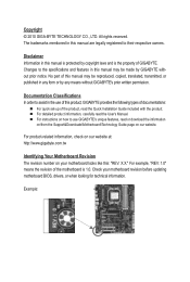
... without prior notice. Documentation Classifications In order to assist in the use GIGABYTE's unique features, read or download the information on/from the Support&Downloads\Motherboard\Technology Guide page on our website. For detailed product information, carefully read...included with the product. Disclaimer Information in any form or by GIGABYTE without GIGABYTE's prior written permission. Changes to their respective owners. Example: For instructions on your motherboard revision before updating motherboard BIOS, drivers, or when looking for technical information. For ...
... without prior notice. Documentation Classifications In order to assist in the use GIGABYTE's unique features, read or download the information on/from the Support&Downloads\Motherboard\Technology Guide page on our website. For detailed product information, carefully read...included with the product. Disclaimer Information in any form or by GIGABYTE without GIGABYTE's prior written permission. Changes to their respective owners. Example: For instructions on your motherboard revision before updating motherboard BIOS, drivers, or when looking for technical information. For ...
Manual
Page 4
Table of Contents Box Contents...6 Optional Items...6 GA-785GMT-USB3 Motherboard Layout 7 GA-785GMT-USB3 Motherboard Block Diagram 8 Chapter 1 Hardware Installation 9 1-1 Installation Precautions 9 1-2 Product Specifications 10 1-3 Installing the CPU and CPU Cooler 13 1-3-1 Installing the CPU 13 1-3-2 Installing the CPU Cooler ...
Table of Contents Box Contents...6 Optional Items...6 GA-785GMT-USB3 Motherboard Layout 7 GA-785GMT-USB3 Motherboard Block Diagram 8 Chapter 1 Hardware Installation 9 1-1 Installation Precautions 9 1-2 Product Specifications 10 1-3 Installing the CPU and CPU Cooler 13 1-3-1 Installing the CPU 13 1-3-2 Installing the CPU Cooler ...
Manual
Page 6
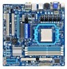
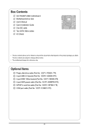
... 12CF1-2SERPW-0*R) S/PDIF In and Out cable (Part No. 12CR1-1SPINO-1*R) COM port cable (Part No. 12CF1-1CM001-3*R) - 6 - Box Contents GA-785GMT-USB3 motherboard Motherboard driver disk User's Manual Quick Installation Guide One IDE cable Two SATA 3Gb/s cables I/O Shield • The box contents above are subject to change ...without notice. • The motherboard image is for reference only and the actual items shall depend on the product package you obtain. The box contents are for reference only....
... 12CF1-2SERPW-0*R) S/PDIF In and Out cable (Part No. 12CR1-1SPINO-1*R) COM port cable (Part No. 12CF1-1CM001-3*R) - 6 - Box Contents GA-785GMT-USB3 motherboard Motherboard driver disk User's Manual Quick Installation Guide One IDE cable Two SATA 3Gb/s cables I/O Shield • The box contents above are subject to change ...without notice. • The motherboard image is for reference only and the actual items shall depend on the product package you obtain. The box contents are for reference only....
Manual
Page 7
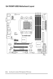
FDD ATX GA-785GMT-USB3 Motherboard Layout DDR3_1 DDR3_2 DDR3_3 DDR3_4 M_BIOS IT8720 DVI VGA KB(Note)_USB CPU_FAN ATX_12V_2X4 Socket AM3 B_BIOS SPDIF HDMI USB 1394 USB30 ESATA LAN AUDIO NEC D720200F1 F_AUDIO PCIEX1 GA-785GMT-USB3 AMD 785G PCIEX16 RTL8111D PCI1 CD_IN CODEC PCI2 CLR_CMOS SPDIF_IO COM F_1394_1 BATTERY TSB43AB23 SYS_FAN AMD SB710 SATA2_4 SATA2_1 SATA2_3 F_USB3 F_USB2 F_USB1 F_PANEL IDE SATA2_0 SATA2_2 (Note) Use this port to connect a PS/2 keyboard or PS/2 mouse. - 7 -
FDD ATX GA-785GMT-USB3 Motherboard Layout DDR3_1 DDR3_2 DDR3_3 DDR3_4 M_BIOS IT8720 DVI VGA KB(Note)_USB CPU_FAN ATX_12V_2X4 Socket AM3 B_BIOS SPDIF HDMI USB 1394 USB30 ESATA LAN AUDIO NEC D720200F1 F_AUDIO PCIEX1 GA-785GMT-USB3 AMD 785G PCIEX16 RTL8111D PCI1 CD_IN CODEC PCI2 CLR_CMOS SPDIF_IO COM F_1394_1 BATTERY TSB43AB23 SYS_FAN AMD SB710 SATA2_4 SATA2_1 SATA2_3 F_USB3 F_USB2 F_USB1 F_PANEL IDE SATA2_0 SATA2_2 (Note) Use this port to connect a PS/2 keyboard or PS/2 mouse. - 7 -
Manual
Page 8
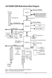
GA-785GMT-USB3 Motherboard Block Diagram PCIe CLK (100 MHz) 1 PCI Express x16 CPU CLK+/- (200 MHz) AM3 CPU DDR3 1800 (O.C.)/1333/1066 MHz Dual Channel Memory Hyper Transport 3.0 ...
GA-785GMT-USB3 Motherboard Block Diagram PCIe CLK (100 MHz) 1 PCI Express x16 CPU CLK+/- (200 MHz) AM3 CPU DDR3 1800 (O.C.)/1333/1066 MHz Dual Channel Memory Hyper Transport 3.0 ...
Manual
Page 9
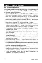
... an electrostatic discharge (ESD) wrist strap when handling electronic com- Hardware Installation Chapter 1 Hardware Installation 1-1 Installation Precautions The motherboard contains numerous delicate electronic circuits and components which can lead to damage to system components as well as physical harm to the... shielding container. • Before unplugging the power supply cable from the power outlet before installing or removing the motherboard or other hardware components. • When connecting hardware components to the internal connectors on the computer power during ...
... an electrostatic discharge (ESD) wrist strap when handling electronic com- Hardware Installation Chapter 1 Hardware Installation 1-1 Installation Precautions The motherboard contains numerous delicate electronic circuits and components which can lead to damage to system components as well as physical harm to the... shielding container. • Before unplugging the power supply cable from the power outlet before installing or removing the motherboard or other hardware components. • When connecting hardware components to the internal connectors on the computer power during ...

Manual
Page 12
... CPU/system fan speed control function is supported will depend on the CPU/system cooler you install. (Note 6) Available functions in EasyTune may differ by motherboard model. Hardware Installation - 12 -
... CPU/system fan speed control function is supported will depend on the CPU/system cooler you install. (Note 6) Available functions in EasyTune may differ by motherboard model. Hardware Installation - 12 -
Manual
Page 13
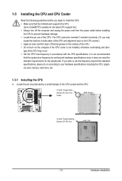
... standard requirements for the latest CPU support list.) • Always turn on the computer if the CPU cooler is not recommended that the motherboard supports the CPU. (Go to GIGABYTE's website for the peripherals. It is not installed, otherwise overheating and dam- Locate the pin one of the CPU. A Small Triangle Mark...
... standard requirements for the latest CPU support list.) • Always turn on the computer if the CPU cooler is not recommended that the motherboard supports the CPU. (Go to GIGABYTE's website for the peripherals. It is not installed, otherwise overheating and dam- Locate the pin one of the CPU. A Small Triangle Mark...
Manual
Page 14
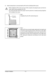
... the CPU into the CPU socket. B. The CPU cannot fit in if oriented incorrectly. Follow the steps below to correctly install the CPU into the motherboard CPU socket. • Before installing the CPU, make sure to turn off the computer and unplug the power cord from the power outlet to prevent...
... the CPU into the CPU socket. B. The CPU cannot fit in if oriented incorrectly. Follow the steps below to correctly install the CPU into the motherboard CPU socket. • Before installing the CPU, make sure to turn off the computer and unplug the power cord from the power outlet to prevent...
Manual
Page 15
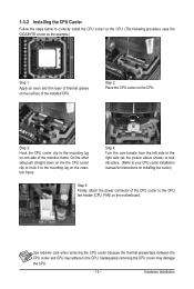
...to the CPU. 1-3-2 Installing the CPU Cooler Follow the steps below to correctly install the CPU cooler on the CPU. (The following procedure uses the GIGABYTE cooler as the picture above shows) to lock into place. (Refer to your CPU cooler installation manual for instructions on installing the cooler.) Step 5:... handle from the left side to the right side (as the example.) Step 1: Apply an even and thin layer of thermal grease on the motherboard. Step 2: Place the CPU cooler on the CPU. Use extreme care when removing the CPU cooler because the thermal grease/tape between the CPU ...
...to the CPU. 1-3-2 Installing the CPU Cooler Follow the steps below to correctly install the CPU cooler on the CPU. (The following procedure uses the GIGABYTE cooler as the picture above shows) to lock into place. (Refer to your CPU cooler installation manual for instructions on installing the cooler.) Step 5:... handle from the left side to the right side (as the example.) Step 1: Apply an even and thin layer of thermal grease on the motherboard. Step 2: Place the CPU cooler on the CPU. Use extreme care when removing the CPU cooler because the thermal grease/tape between the CPU ...
Manual
Page 16
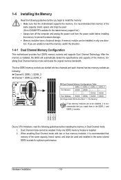
...be enabled if only one direction. When enabling Dual Channel mode with two or four memory modules, it is recommended that the motherboard supports the memory. DDR3_1 DDR3_2 DDR3_3 DDR3_4 Due to prevent hardware damage. • Memory modules have a foolproof design. Dual ...bandwidth. The four DDR3 memory sockets are unable to insert the memory, switch the direction. 1-4-1 Dual Channel Memory Configuration This motherboard provides four DDR3 memory sockets and supports Dual Channel Technology. 1-4 Installing the Memory Read the following guidelines before installing the ...
...be enabled if only one direction. When enabling Dual Channel mode with two or four memory modules, it is recommended that the motherboard supports the memory. DDR3_1 DDR3_2 DDR3_3 DDR3_4 Due to prevent hardware damage. • Memory modules have a foolproof design. Dual ...bandwidth. The four DDR3 memory sockets are unable to insert the memory, switch the direction. 1-4-1 Dual Channel Memory Configuration This motherboard provides four DDR3 memory sockets and supports Dual Channel Technology. 1-4 Installing the Memory Read the following guidelines before installing the ...

Manual
Page 17
... picture on the left, place your fingers on the memory and insert it can only fit in one direction. Place the memory module on this motherboard. Follow the steps below to install DDR3 DIMMs on the socket. Step 1: Note the orientation of the memory socket. 1-4-2 Installing a Memory Before installing a memory module...
... picture on the left, place your fingers on the memory and insert it can only fit in one direction. Place the memory module on this motherboard. Follow the steps below to install DDR3 DIMMs on the socket. Step 1: Note the orientation of the memory socket. 1-4-2 Installing a Memory Before installing a memory module...
Manual
Page 18
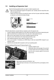
... Express slot. PCI Express x1 Slot PCI Express x16 Slot PCI Slot Follow the steps below to install an expansion card: • Make sure the motherboard supports the expansion card.
... Express slot. PCI Express x1 Slot PCI Express x16 Slot PCI Slot Follow the steps below to install an expansion card: • Make sure the motherboard supports the expansion card.
Manual
Page 19
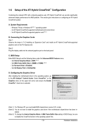
... with a discrete graphics card, ATI Hybrid CrossFireX can provide significantly advanced display performance for AMD platform. An ATI Hybrid CrossFireX-supported motherboard and correct driver - stalled. (Note 3) To change the Internal Graphics Mode or UMA Frame Buffer Size setting in - Hardware ... ATI Hybrid CrossFireX system. Windows 7/Vista or Windows XP (Note 1) operating system - Configuring the Graphics Driver After installing the motherboard driver in "1-5 Installing an Expansion Card" and install an ATI Hybrid CrossFireX-supported graphics card on the upper left corner and ...
... with a discrete graphics card, ATI Hybrid CrossFireX can provide significantly advanced display performance for AMD platform. An ATI Hybrid CrossFireX-supported motherboard and correct driver - stalled. (Note 3) To change the Internal Graphics Mode or UMA Frame Buffer Size setting in - Hardware ... ATI Hybrid CrossFireX system. Windows 7/Vista or Windows XP (Note 1) operating system - Configuring the Graphics Driver After installing the motherboard driver in "1-5 Installing an Expansion Card" and install an ATI Hybrid CrossFireX-supported graphics card on the upper left corner and ...
Manual
Page 21
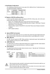
... short inside the cable connector. - 21 - Use this feature, ensure that supports digital optical audio. Hardware Installation Do not rock it straight out from the motherboard. • When removing the cable, pull it side to side to Chapter 2, "BIOS Setup," "Advanced BIOS Features," for an IEEE 1394a device. RJ-45 LAN... then remove it from the connector. Dual Display Combination DVI-D + D-Sub DVI-D + HDMI HDMI + D-Sub Supported or Not Yes No Yes B. A. Dual Display Configurations: This motherboard provides three ports for video output: DVI-D, HDMI and D-Sub.
... short inside the cable connector. - 21 - Use this feature, ensure that supports digital optical audio. Hardware Installation Do not rock it straight out from the motherboard. • When removing the cable, pull it side to side to Chapter 2, "BIOS Setup," "Advanced BIOS Features," for an IEEE 1394a device. RJ-45 LAN... then remove it from the connector. Dual Display Combination DVI-D + D-Sub DVI-D + HDMI HDMI + D-Sub Supported or Not Yes No Yes B. A. Dual Display Configurations: This motherboard provides three ports for video output: DVI-D, HDMI and D-Sub.
Manual
Page 23
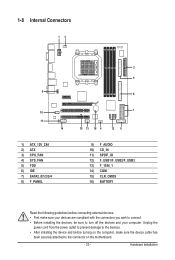
... 8 9) F_AUDIO 10) CD_IN 11) SPDIF_IO 12) F_USB1/F_USB2/F_USB3 13) F_1394_1 14) COM 15) CLR_CMOS 16) BATTERY Read the following guidelines before turning on the motherboard. - 23 - Unplug the power cord from the power outlet to prevent damage to the devices. • After installing the device and before connecting external devices...
... 8 9) F_AUDIO 10) CD_IN 11) SPDIF_IO 12) F_USB1/F_USB2/F_USB3 13) F_1394_1 14) COM 15) CLR_CMOS 16) BATTERY Read the following guidelines before turning on the motherboard. - 23 - Unplug the power cord from the power outlet to prevent damage to the devices. • After installing the device and before connecting external devices...
Manual
Page 24
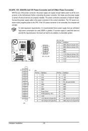
... mainly supplies power to an unstable or unbootable system. 1 5 4 8 ATX_12V_2X4 ATX_12V_2X4: Pin No. If a power supply is turned off and all the components on the motherboard. If the 12V power connector is recommended that a power supply that can withstand high power consumption be used that does not provide the required power...
... mainly supplies power to an unstable or unbootable system. 1 5 4 8 ATX_12V_2X4 ATX_12V_2X4: Pin No. If a power supply is turned off and all the components on the motherboard. If the 12V power connector is recommended that a power supply that can withstand high power consumption be used that does not provide the required power...

Manual
Page 25
... local dealer. 34 33 2 1 - 25 - The pin 1 of the cable is the ground wire. Hardware Installation 3/4) CPU_FAN/SYS_FAN (Fan Headers) The motherboard has a 4-pin CPU fan header (CPU_FAN)and a 4-pin system fan header(SYS_FAN). When connecting a fan cable, be sure to prevent your CPU, North Bridge... and system from overheating. The black connector wire is typically designated by a stripe of the connector and the floppy disk drive cable. The motherboard supports CPU fan speed control, which requires the use of floppy disk drives supported are: 360 KB, 720 KB, 1.2 MB, 1.44 MB,...
... local dealer. 34 33 2 1 - 25 - The pin 1 of the cable is the ground wire. Hardware Installation 3/4) CPU_FAN/SYS_FAN (Fan Headers) The motherboard has a 4-pin CPU fan header (CPU_FAN)and a 4-pin system fan header(SYS_FAN). When connecting a fan cable, be sure to prevent your CPU, North Bridge... and system from overheating. The black connector wire is typically designated by a stripe of the connector and the floppy disk drive cable. The motherboard supports CPU fan speed control, which requires the use of floppy disk drives supported are: 360 KB, 720 KB, 1.2 MB, 1.44 MB,...


