
Owner's Manual
Page 2
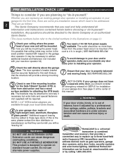
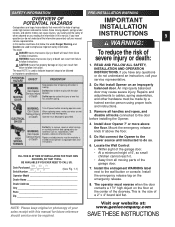
...the garage door operator. The outlet should consider an emergency release kit (GER-2) for the first time, there are available through your local Genie Dealer. 4 Is your garage door made of your garage does not have it is mounted. (The cord is properly balanced and moving freely... instructions contained herein before choosing a "do -it -yourself " installation. The brackets may be addressed. 2 They are as gate operators, garage door openers, entry door locks, security systems and even home lighting. If this is possible that your new door operator kit). 5 You need to be attached...
...the garage door operator. The outlet should consider an emergency release kit (GER-2) for the first time, there are available through your local Genie Dealer. 4 Is your garage door made of your garage does not have it is mounted. (The cord is properly balanced and moving freely... instructions contained herein before choosing a "do -it -yourself " installation. The brackets may be addressed. 2 They are as gate operators, garage door openers, entry door locks, security systems and even home lighting. If this is possible that your new door operator kit). 5 You need to be attached...
Owner's Manual
Page 4
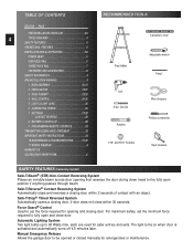
...not close door. Manual Emergency Release Allows the garage door to the fully open and close within 2 seconds of contact with an object. Safe-T-Stop® Timed Reversed System Automatically opens a closing door within 30 seconds. each are used for emergencies or maintenance... B ACCESSORIES ORDER FORM C RECOMMENDED TOOLS Carpenter's level Step ladder Adjustable wrench Pencil Drill 5/ 32" Drill Bit Ratchet Wire strippers Phillips screwdriver 7/16" and 9/16" Sockets Tape measure SAFETY FEATURES (varies by model) Safe-T-Beam® (STB) Non-Contact Reversing System Places...
...not close door. Manual Emergency Release Allows the garage door to the fully open and close within 2 seconds of contact with an object. Safe-T-Stop® Timed Reversed System Automatically opens a closing door within 30 seconds. each are used for emergencies or maintenance... B ACCESSORIES ORDER FORM C RECOMMENDED TOOLS Carpenter's level Step ladder Adjustable wrench Pencil Drill 5/ 32" Drill Bit Ratchet Wire strippers Phillips screwdriver 7/16" and 9/16" Sockets Tape measure SAFETY FEATURES (varies by model) Safe-T-Beam® (STB) Non-Contact Reversing System Places...
Owner's Manual
Page 5
... Console (some models) Operates door operator from a working system and tried again will not control the door operator. Controls door opener from inside garage. NOTE: All items may not be opened and closed remotely. Makes console easy to each time the remote control is powered, locked or unlocked. INTELLICODE® Multi-Button...
... Console (some models) Operates door operator from a working system and tried again will not control the door operator. Controls door opener from inside garage. NOTE: All items may not be opened and closed remotely. Makes console easy to each time the remote control is powered, locked or unlocked. INTELLICODE® Multi-Button...
Owner's Manual
Page 6
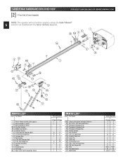
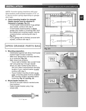
... Nut 6 Carriage Stop 7 Rail Clamps 8 5/16" Hex Shoulder Bolt 9 5/16" Hex Flange Nut 10 Carriage Assembly 11 Collar 12 Retaining Clip 13 Rail Strap 15A Open Limit Switch Assembly (Grey) Parts Required 1 Piece 3-Piece 1 1 1 1 1 1 1 2 2 2 2 1 1 4 8 5 13 1 1 2 2 1 1 1 1 PARTS LIST Item Part Name 15B Close Limit Switch Assembly (Brown) 16 No. 8-32 x 3/8" Hex Head...
... Nut 6 Carriage Stop 7 Rail Clamps 8 5/16" Hex Shoulder Bolt 9 5/16" Hex Flange Nut 10 Carriage Assembly 11 Collar 12 Retaining Clip 13 Rail Strap 15A Open Limit Switch Assembly (Grey) Parts Required 1 Piece 3-Piece 1 1 1 1 1 1 1 2 2 2 2 1 1 4 8 5 13 1 1 2 2 1 1 1 1 PARTS LIST Item Part Name 15B Close Limit Switch Assembly (Brown) 16 No. 8-32 x 3/8" Hex Head...
Owner's Manual
Page 9
.... Install the entrapment WARNING label next to play with the door operator. MOVING DOOR WARNING: Can Cause Serious Injury or Death Keep people clear of opening while door is the size of a 2" x 4" board laid flat. MM DD YY Date Purchased WK YY PI (See Fig. 1-1) Serial Number...moving objects, springs under high tension and electric motors. WARNING: Can Cause Serious Injury or Death ELECTRICAL SHOCK Turn off power before installing the Opener. 4. Remove all handles and ropes, and disable all moving . FILL THIS IN AT TIME OF INSTALLATION FOR YOUR OWN RECORDS, SO THAT...
.... Install the entrapment WARNING label next to play with the door operator. MOVING DOOR WARNING: Can Cause Serious Injury or Death Keep people clear of opening while door is the size of a 2" x 4" board laid flat. MM DD YY Date Purchased WK YY PI (See Fig. 1-1) Serial Number...moving objects, springs under high tension and electric motors. WARNING: Can Cause Serious Injury or Death ELECTRICAL SHOCK Turn off power before installing the Opener. 4. Remove all handles and ropes, and disable all moving . FILL THIS IN AT TIME OF INSTALLATION FOR YOUR OWN RECORDS, SO THAT...

Owner's Manual
Page 10
... coupler. • Slide rail section into position as needed until operator is fully assembled. 5. Fig. 1-3. • Place bearing end of rail sections. SECT 1-MAIN ASSEMBLY OPEN BLUE PARTS BAG NOTE: 3-piece rail assembly is for 8 feet doors is available. 1. Fig. 1-1. Fig. 1-1. 4. Fig. 1-4.
... coupler. • Slide rail section into position as needed until operator is fully assembled. 5. Fig. 1-3. • Place bearing end of rail sections. SECT 1-MAIN ASSEMBLY OPEN BLUE PARTS BAG NOTE: 3-piece rail assembly is for 8 feet doors is available. 1. Fig. 1-1. Fig. 1-1. 4. Fig. 1-4.

Owner's Manual
Page 14
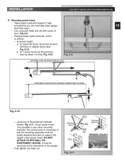
... release lever (on side away from power head. (This means limit switches hang off opposite sides of rail. Fig. 1-19A. - Place "OPEN" limit switch over top of rail about 12 inches from power head. Check this to help maintain slack. Place "CLOSE" limit switch over top...18]. Insert set screw [16] into limit switch hand tight only to temporarily hold switch in place. - Fig. 1-19B. - Fig. 1-20. • "OPEN" limit switch [15A]. - Insert set screw [16] into limit switch hand tight only to temporarily hold switch in place. Fig. 1-21. • Coil excess ...
... release lever (on side away from power head. (This means limit switches hang off opposite sides of rail. Fig. 1-19A. - Place "OPEN" limit switch over top of rail about 12 inches from power head. Check this to help maintain slack. Place "CLOSE" limit switch over top...18]. Insert set screw [16] into limit switch hand tight only to temporarily hold switch in place. - Fig. 1-19B. - Fig. 1-20. • "OPEN" limit switch [15A]. - Insert set screw [16] into limit switch hand tight only to temporarily hold switch in place. Fig. 1-21. • Coil excess ...

Owner's Manual
Page 16
... door Fig. 2-4 Fig. 2-3. Measure from top edge to floor Fig. 2-2 +2-1/2" +6" Highest point of travel . centerline of door Fig. 2-3 centerline of travel . With door held partly open (at centerline on centerline. NOTE: Following step depends on centerline. add 6 inches to "highest point of door. 3. add 2-1/2 inches to "highest point of travel " and...
... door Fig. 2-4 Fig. 2-3. Measure from top edge to floor Fig. 2-2 +2-1/2" +6" Highest point of travel . centerline of door Fig. 2-3 centerline of travel . With door held partly open (at centerline on centerline. NOTE: Following step depends on centerline. add 6 inches to "highest point of door. 3. add 2-1/2 inches to "highest point of travel " and...
Owner's Manual
Page 17
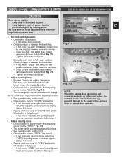
...is finished (covered with drywall), continue with step 6. - If your wall is above torsion spring depending on garage header door type. garage door opening OPEN ORANGE PARTS BAG TYPICAL FINISHED WALL floor Fig. 2-5 5. Fig. 2-6. • Mark screw hole locations. - TYPICAL UNFINISHED WALL floor •... where you have marked screw holes to framework of door flange for rail strap Fig. 2-6 flange for strength. garage door opening • If final header bracket position is wood behind mounting location. Header bracket must be attached to find out if there...
...is finished (covered with drywall), continue with step 6. - If your wall is above torsion spring depending on garage header door type. garage door opening OPEN ORANGE PARTS BAG TYPICAL FINISHED WALL floor Fig. 2-5 5. Fig. 2-6. • Mark screw hole locations. - TYPICAL UNFINISHED WALL floor •... where you have marked screw holes to framework of door flange for rail strap Fig. 2-6 flange for strength. garage door opening • If final header bracket position is wood behind mounting location. Header bracket must be attached to find out if there...
Owner's Manual
Page 19
... be level with center of the preferred methods shown, Fig. 2-11, mount power head. (It is that you can manually raise garage 19 door fully open. • Line up power head and rail with floor or slightly below level. Fig. 2-9 SECTIONAL LEVEL OR SLIGHTLY BELOW LEVEL 1-PIECE MUST CLEAR DOOR BY...
... be level with center of the preferred methods shown, Fig. 2-11, mount power head. (It is that you can manually raise garage 19 door fully open. • Line up power head and rail with floor or slightly below level. Fig. 2-9 SECTIONAL LEVEL OR SLIGHTLY BELOW LEVEL 1-PIECE MUST CLEAR DOOR BY...
Owner's Manual
Page 21
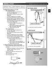
... possible. Use clevis pin [24] and cotter pin [25]. - Fig. 2-14. c. Adjust emergency release knob height. • Knob should be as short as possible. INSTALLATION OPEN YELLOW PARTS BAG 10. b. Fig. 2-14. - Overall length of arms together should hang approximately 6 feet from the floor. - adjust as necessary to door bracket. Fig...
... possible. Use clevis pin [24] and cotter pin [25]. - Fig. 2-14. c. Adjust emergency release knob height. • Knob should be as short as possible. INSTALLATION OPEN YELLOW PARTS BAG 10. b. Fig. 2-14. - Overall length of arms together should hang approximately 6 feet from the floor. - adjust as necessary to door bracket. Fig...
Owner's Manual
Page 22
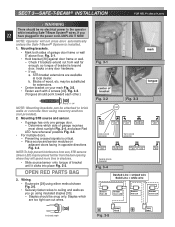
...frame or wall 5" above floor. may be substituted for extensions. • Center bracket on adjacent doors facing in opposite directions Fig. 3-4. OPEN RED PARTS BAG 3. NOTE: Operator will spend more time in the power cord-UNPLUG IT NOW. Staples which side of bracket until it clicks... • For multiple doors. - Check if brackets extend out from sun, STB sensors (Green LED) may be placed further from the door opening where they will not close door automatically unless the Safe-T-Beam® System is critical. - Wiring. • Route wire [29] using insulated staples ...
...frame or wall 5" above floor. may be substituted for extensions. • Center bracket on adjacent doors facing in opposite directions Fig. 3-4. OPEN RED PARTS BAG 3. NOTE: Operator will spend more time in the power cord-UNPLUG IT NOW. Staples which side of bracket until it clicks... • For multiple doors. - Check if brackets extend out from sun, STB sensors (Green LED) may be placed further from the door opening where they will not close door automatically unless the Safe-T-Beam® System is critical. - Wiring. • Route wire [29] using insulated staples ...
Owner's Manual
Page 25
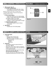
... to work . Whenever possible, use short neck bulbs. - Fig. 5-2. bottom of lens cover hooks into slots at bottom of lens Fig. 5-2 [42] #8 x 3/8" Pan head screw A. Opens and closes door from inside garage. - Wall Button - No more than 60 watts each. - Check for alignment between the screw holes in front plate Fig...
... to work . Whenever possible, use short neck bulbs. - Fig. 5-2. bottom of lens cover hooks into slots at bottom of lens Fig. 5-2 [42] #8 x 3/8" Pan head screw A. Opens and closes door from inside garage. - Wall Button - No more than 60 watts each. - Check for alignment between the screw holes in front plate Fig...
Owner's Manual
Page 27
...limit switch back toward Powerhead until Lever snaps into engaged position. • On front panel of power head to prevent being hit by turning "OPEN" adjusting screw clockwise slightly (about 1/16 turn ). • Repeat until door runs to achieve fully closed . - If not, move "...CLOSE" limit switch (brown wire) to achieve fully open. lever (actuator arm) fully lifted CARRIAGE SLIDE 27 SWITCH 1. Tighten limit switch set force adjustments at minimum required to "CLOSE" limit switch. - Fig...
...limit switch back toward Powerhead until Lever snaps into engaged position. • On front panel of power head to prevent being hit by turning "OPEN" adjusting screw clockwise slightly (about 1/16 turn ). • Repeat until door runs to achieve fully closed . - If not, move "...CLOSE" limit switch (brown wire) to achieve fully open. lever (actuator arm) fully lifted CARRIAGE SLIDE 27 SWITCH 1. Tighten limit switch set force adjustments at minimum required to "CLOSE" limit switch. - Fig...
Owner's Manual
Page 28
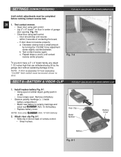
... reverse works properly. Install / replace battery Fig. 8-1. • Using a pen or similar object, gently push in slot on tab. • Cover snaps open. Attach visor clip Fig. 6-1. • Slide clip in on back of remote control. - Snap in center of contacting the board. - Fig. 7-3 *...door. Visor Clip Model Number Battery Cover Battery Fig. 8-1 If door does not reverse properly: a. Test contact reverse. • Open door using wall control. - Decrease closing force a small amount by the garage door without sustaining damage is stopping but not reversing, ...
... reverse works properly. Install / replace battery Fig. 8-1. • Using a pen or similar object, gently push in slot on tab. • Cover snaps open. Attach visor clip Fig. 6-1. • Slide clip in on back of remote control. - Snap in center of contacting the board. - Fig. 7-3 *...door. Visor Clip Model Number Battery Cover Battery Fig. 8-1 If door does not reverse properly: a. Test contact reverse. • Open door using wall control. - Decrease closing force a small amount by the garage door without sustaining damage is stopping but not reversing, ...
Owner's Manual
Page 29
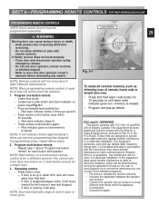
... designed to radio communications. However, there is moving . • Do not allow children to play with FCC Part 15 and RSS 210 of open or close door if Safe-T-Beam® malfunctions. Program one or more than one -button remote" for a single door. 3. Red indicator goes...does not work properly: • Close door and disconnect operator using emergency release. • Do not use more of the following loss of opening while door is connected. • Consult the dealer. SECT 9-PROGRAMMING REMOTE CONTROLS FOR HELP-GENIECOMPANY.COM PROGRAMMING REMOTE CONTROLS NOTE: Each remote ...
... designed to radio communications. However, there is moving . • Do not allow children to play with FCC Part 15 and RSS 210 of open or close door if Safe-T-Beam® malfunctions. Program one or more than one -button remote" for a single door. 3. Red indicator goes...does not work properly: • Close door and disconnect operator using emergency release. • Do not use more of the following loss of opening while door is connected. • Consult the dealer. SECT 9-PROGRAMMING REMOTE CONTROLS FOR HELP-GENIECOMPANY.COM PROGRAMMING REMOTE CONTROLS NOTE: Each remote ...
Owner's Manual
Page 30
... door increases the risk of travel, retest the Door Opener. TRANSMITTER COMPLIANCE STATEMENT 30 Transmitters comply with the door open. NO ONE SHOULD CROSS THE PATH OF THE MOVING DOOR. 4 NEVER GO UNDER A STOPPED, PARTIALLY OPEN DOOR. 5 Test Opener monthly. Aucune garantie n est stipul e indiquant qu ils... prior to be used in anderen L ndern. Failure to cables, spring assemblies, and other jurisdiction. Have a Genie Factory Authorized Dealer make repairs to adjust the Opener properly may differ from people and objects until the door is closed . Use caution when using this Release with...
... door increases the risk of travel, retest the Door Opener. TRANSMITTER COMPLIANCE STATEMENT 30 Transmitters comply with the door open. NO ONE SHOULD CROSS THE PATH OF THE MOVING DOOR. 4 NEVER GO UNDER A STOPPED, PARTIALLY OPEN DOOR. 5 Test Opener monthly. Aucune garantie n est stipul e indiquant qu ils... prior to be used in anderen L ndern. Failure to cables, spring assemblies, and other jurisdiction. Have a Genie Factory Authorized Dealer make repairs to adjust the Opener properly may differ from people and objects until the door is closed . Use caution when using this Release with...
Owner's Manual
Page 32
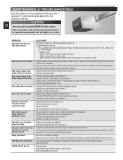
...but door does not move. If not, check fuse or circuit breaker. • If power is engaged. Motor protector may be open . Check for shorted wires Check force adjustment (See Section 7). Relocate remote control inside car. Do Not attempt to correct problems with... run from remote control. Check connections at door. Was a remote control lost or stolen? Check OPEN limit switch for broken door spring. Check force adjustment (See Section 7). Check OPEN limit switch setting (See section 7). Check force adjustment (See Section 7). Operator runs, but not from...
...but door does not move. If not, check fuse or circuit breaker. • If power is engaged. Motor protector may be open . Check for shorted wires Check force adjustment (See Section 7). Relocate remote control inside car. Do Not attempt to correct problems with... run from remote control. Check connections at door. Was a remote control lost or stolen? Check OPEN limit switch for broken door spring. Check force adjustment (See Section 7). Check OPEN limit switch setting (See section 7). Check force adjustment (See Section 7). Operator runs, but not from...


