8511725 - Gateway Service Guide
Page 3
... 2 Identifying components 3 Preparing your work space 4 Preventing static electricity discharge 5 Tape 5 Preparing the notebook 6 Removing the battery 6 Adding or replacing memory modules 7 Replacing the DVD drive 11 Replacing the cooling assembly 14 Replacing the processor 19 Replacing the IEEE ...
... 2 Identifying components 3 Preparing your work space 4 Preventing static electricity discharge 5 Tape 5 Preparing the notebook 6 Removing the battery 6 Adding or replacing memory modules 7 Replacing the DVD drive 11 Replacing the cooling assembly 14 Replacing the processor 19 Replacing the IEEE ...
8511725 - Gateway Service Guide
Page 5
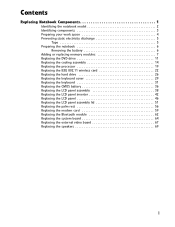
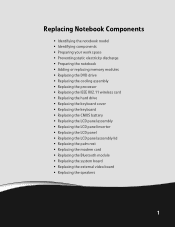
... • Identifying components • Preparing your work space • Preventing static electricity discharge • Preparing the notebook • Adding or replacing memory modules • Replacing the DVD drive • Replacing the cooling assembly • Replacing the processor • Replacing the IEEE 802....
... • Identifying components • Preparing your work space • Preventing static electricity discharge • Preparing the notebook • Adding or replacing memory modules • Replacing the DVD drive • Replacing the cooling assembly • Replacing the processor • Replacing the IEEE 802....
8511725 - Gateway Service Guide
Page 6
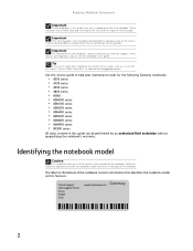
... and finishing of the case and the shape of the notebook contains information that you use the correct service guide for the notebook. Online Support: Tech Support Phone: Hours: Model: S/No: support.gateway.com 2 Replacing Notebook Components Important The photographs in this guide, send an e-...mail with the subject "Service Guide Comments" to channel.services@gateway.com. These variations may vary in appearance from the notebook. Important For information on the bottom of the touchpad. Identifying the notebook model Caution It is not intended to be provided to anyone ...
... and finishing of the case and the shape of the notebook contains information that you use the correct service guide for the notebook. Online Support: Tech Support Phone: Hours: Model: S/No: support.gateway.com 2 Replacing Notebook Components Important The photographs in this guide, send an e-...mail with the subject "Service Guide Comments" to channel.services@gateway.com. These variations may vary in appearance from the notebook. Important For information on the bottom of the touchpad. Identifying the notebook model Caution It is not intended to be provided to anyone ...
8511725 - Gateway Service Guide
Page 7
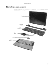
LCD panel assembly (see page 38) Keyboard cover (see page 29) Keyboard (see page 31) Cooling assembly (see page 11) Processor (see page 19) Palm rest (see "Contents" on page i. For a complete list of the notebook. www.gateway.com Identifying components Use this chart to identify the main components of replaceable parts, see page 56) 3
LCD panel assembly (see page 38) Keyboard cover (see page 29) Keyboard (see page 31) Cooling assembly (see page 11) Processor (see page 19) Palm rest (see "Contents" on page i. For a complete list of the notebook. www.gateway.com Identifying components Use this chart to identify the main components of replaceable parts, see page 56) 3
8511725 - Gateway Service Guide
Page 8
... on your work surface. • Print the first page of each task, then place the page toward the rear of your work surface (behind the notebook) or far enough to the side that are deeply recessed in a hole (for removing screws. • When removing components that are attached to the... notebook by a cable, unplug the cable before removing the screws, when possible, to avoid damaging the cable. • As you remove components and screws, lay them ...
... on your work surface. • Print the first page of each task, then place the page toward the rear of your work surface (behind the notebook) or far enough to the side that are deeply recessed in a hole (for removing screws. • When removing components that are attached to the... notebook by a cable, unplug the cable before removing the screws, when possible, to avoid damaging the cable. • As you remove components and screws, lay them ...
8511725 - Gateway Service Guide
Page 9
...antistatic bags only when you should be reused, replace it to use cellophane tape. 5 Tape Some of the procedures in this Gateway notebook: • Mylar, non-conductive tape is typically grey or silver. Two types of tape are used in this section. Both..., and network cable before opening the case. Important Before performing maintenance on the notebook, follow these guidelines: • Avoid static-causing surfaces such as electrostatic discharge (ESD). www.gateway.com Preventing static electricity discharge Warning To avoid exposure to static electricity, also known...
...antistatic bags only when you should be reused, replace it to use cellophane tape. 5 Tape Some of the procedures in this Gateway notebook: • Mylar, non-conductive tape is typically grey or silver. Two types of tape are used in this section. Both..., and network cable before opening the case. Important Before performing maintenance on the notebook, follow these guidelines: • Avoid static-causing surfaces such as electrostatic discharge (ESD). www.gateway.com Preventing static electricity discharge Warning To avoid exposure to static electricity, also known...

8511725 - Gateway Service Guide
Page 10
... Make sure that the DVD drive does not contain a disc. 2 Disconnect all peripheral devices and remove any PC Cards and memory cards. 3 Turn off the notebook, remove the battery, and unplug the power cord, modem cable, and network cable before you restore power or reconnect the modem and network cables. Removing... the battery To remove the battery: 1 Turn the notebook over so the bottom is facing up. 2 Slide the battery lock to dangerous electrical voltages and moving parts, turn off the...
... Make sure that the DVD drive does not contain a disc. 2 Disconnect all peripheral devices and remove any PC Cards and memory cards. 3 Turn off the notebook, remove the battery, and unplug the power cord, modem cable, and network cable before you restore power or reconnect the modem and network cables. Removing... the battery To remove the battery: 1 Turn the notebook over so the bottom is facing up. 2 Slide the battery lock to dangerous electrical voltages and moving parts, turn off the...
8511725 - Gateway Service Guide
Page 11
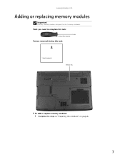
www.gateway.com Adding or replacing memory modules Important Use only memory modules designed for this task: 1 black (keyboard) Memory bay To add or replace memory modules: 1 Complete the steps in "Preparing the notebook" on page 6. 7 Tools you need to complete this task: Phillips #0 screwdriver Screws removed during this Gateway notebook.
www.gateway.com Adding or replacing memory modules Important Use only memory modules designed for this task: 1 black (keyboard) Memory bay To add or replace memory modules: 1 Complete the steps in "Preparing the notebook" on page 6. 7 Tools you need to complete this task: Phillips #0 screwdriver Screws removed during this Gateway notebook.
8511725 - Gateway Service Guide
Page 12
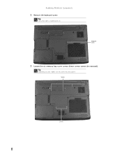
Keyboard screw 3 Loosen the six memory bay cover screws (these screws cannot be captive. Screws Screws 8 Replacing Notebook Components 2 Remove the keyboard screw. Tip Depending on your model, not all screws may be removed). Tip The screw hole is marked with a K.
Keyboard screw 3 Loosen the six memory bay cover screws (these screws cannot be captive. Screws Screws 8 Replacing Notebook Components 2 Remove the keyboard screw. Tip Depending on your model, not all screws may be removed). Tip The screw hole is marked with a K.

8511725 - Gateway Service Guide
Page 14
Tip The screw hole is keyed so it into the empty memory slot. If the module does not fit, make sure that the notch in the module lines up with a K. 10 Replacing Notebook Components 6 Pull the memory module out of the slot. 7 Hold the new or replacement module at a 30-degree angle and press it can only be inserted in one direction. This module is marked with the tab in the memory bay. 8 Replace the memory bay cover, then tighten the cover screws. 9 Replace the keyboard screw.
Tip The screw hole is keyed so it into the empty memory slot. If the module does not fit, make sure that the notch in the module lines up with a K. 10 Replacing Notebook Components 6 Pull the memory module out of the slot. 7 Hold the new or replacement module at a 30-degree angle and press it can only be inserted in one direction. This module is marked with the tab in the memory bay. 8 Replace the memory bay cover, then tighten the cover screws. 9 Replace the keyboard screw.
8511725 - Gateway Service Guide
Page 15
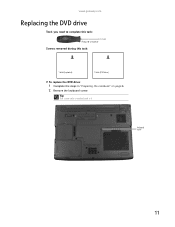
Tip The screw hole is marked with a K. Keyboard screw 11 www.gateway.com Replacing the DVD drive Tools you need to complete this task: Phillips #0 screwdriver Screws removed during this task: 1 black (keyboard) 1 black (DVD drive) To replace the DVD drive: 1 Complete the steps in "Preparing the notebook" on page 6. 2 Remove the keyboard screw.
Tip The screw hole is marked with a K. Keyboard screw 11 www.gateway.com Replacing the DVD drive Tools you need to complete this task: Phillips #0 screwdriver Screws removed during this task: 1 black (keyboard) 1 black (DVD drive) To replace the DVD drive: 1 Complete the steps in "Preparing the notebook" on page 6. 2 Remove the keyboard screw.
8511725 - Gateway Service Guide
Page 16
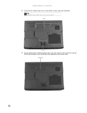
Be careful not to lift the memory bay cover, then remove it. Screws Screws 4 Use the thumb notch to break off the tabs located on your model, not all screws may be removed). Thumb notch 12 Replacing Notebook Components 3 Loosen the six memory bay cover screws (these screws cannot be captive. Tip Depending on the end of the cover opposite of the thumb notch.
Be careful not to lift the memory bay cover, then remove it. Screws Screws 4 Use the thumb notch to break off the tabs located on your model, not all screws may be removed). Thumb notch 12 Replacing Notebook Components 3 Loosen the six memory bay cover screws (these screws cannot be captive. Tip Depending on the end of the cover opposite of the thumb notch.

8511725 - Gateway Service Guide
Page 18
Replacing Notebook Components Replacing the cooling assembly Tools you need to complete this task: Phillips #0 screwdriver Additional materials you may need to complete this task: • X-23-7762 thermal grease Screws removed during this task: 1 black (keyboard) To replace the cooling assembly: 1 Complete the steps in "Preparing the notebook" on page 6. 2 Remove the keyboard screw. Tip The screw hole is marked with a K. Keyboard screw 14
Replacing Notebook Components Replacing the cooling assembly Tools you need to complete this task: Phillips #0 screwdriver Additional materials you may need to complete this task: • X-23-7762 thermal grease Screws removed during this task: 1 black (keyboard) To replace the cooling assembly: 1 Complete the steps in "Preparing the notebook" on page 6. 2 Remove the keyboard screw. Tip The screw hole is marked with a K. Keyboard screw 14
8511725 - Gateway Service Guide
Page 20
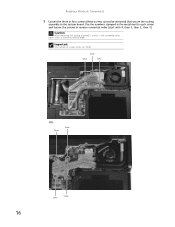
Screw Screw Screw -OR- Replacing Notebook Components 5 Loosen the three or four screws (these screws cannot be removed) that secure the cooling assembly to each screw and loosen the screws in reverse numerical order (start with 4, then 3, then 2, then 1). Screw Screw Screw Screw 16 Important The number of screws varies by model. Caution When loosening the cooling assembly's screws in the numbered holes, loosen them in the metal next to the system board. Use the numbers stamped in reverse numerical order.
Screw Screw Screw -OR- Replacing Notebook Components 5 Loosen the three or four screws (these screws cannot be removed) that secure the cooling assembly to each screw and loosen the screws in reverse numerical order (start with 4, then 3, then 2, then 1). Screw Screw Screw Screw 16 Important The number of screws varies by model. Caution When loosening the cooling assembly's screws in the numbered holes, loosen them in the metal next to the system board. Use the numbers stamped in reverse numerical order.
8511725 - Gateway Service Guide
Page 21
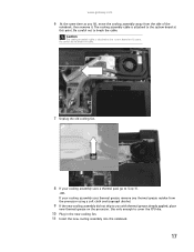
...cooling assembly cable is attached to you lift, move the cooling assembly away from the side of the notebook, then remove it. Be careful not to break the cable. 7 Unplug the old cooling fan.... isopropyl alcohol. 9 If the new cooling assembly did not ship to the system board at this point. www.gateway.com 6 .At the same time as you with thermal grease already applied, place new thermal grease on the ...10 Plug in the new cooling fan. 11 Insert the new cooling assembly into the notebook. 17 Use only enough to break the cable. The cooling assembly cable is attached to the system board ...
...cooling assembly cable is attached to you lift, move the cooling assembly away from the side of the notebook, then remove it. Be careful not to break the cable. 7 Unplug the old cooling fan.... isopropyl alcohol. 9 If the new cooling assembly did not ship to the system board at this point. www.gateway.com 6 .At the same time as you with thermal grease already applied, place new thermal grease on the ...10 Plug in the new cooling fan. 11 Insert the new cooling assembly into the notebook. 17 Use only enough to break the cable. The cooling assembly cable is attached to the system board ...
8511725 - Gateway Service Guide
Page 22
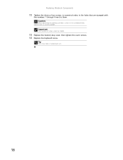
Tip The screw hole is marked with the numbers 1 through 4 next to them in the numbered holes, tighten them . Important The number of screws varies by model. 13 Replace the memory bay cover, then tighten the cover screws. 14 Replace the keyboard screw. Replacing Notebook Components 12 Tighten the three or four screws, in numerical order, in the holes that are stamped with a K. 18 Caution When tightening the cooling assembly's screws in numerical order.
Tip The screw hole is marked with the numbers 1 through 4 next to them in the numbered holes, tighten them . Important The number of screws varies by model. 13 Replace the memory bay cover, then tighten the cover screws. 14 Replace the keyboard screw. Replacing Notebook Components 12 Tighten the three or four screws, in numerical order, in the holes that are stamped with a K. 18 Caution When tightening the cooling assembly's screws in numerical order.
8511725 - Gateway Service Guide
Page 23
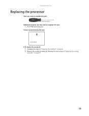
www.gateway.com Replacing the processor Tools you need to complete this task: Phillips #0 screwdriver Additional materials you may need to complete this task: • X-23-7762 thermal grease Screws removed during this task: 1 black (keyboard) To replace the processor: 1 Complete the steps in "Preparing the notebook" on page 6. 2 Remove the cooling assembly by following the instructions in "Replacing the cooling assembly" on page 14. 19
www.gateway.com Replacing the processor Tools you need to complete this task: Phillips #0 screwdriver Additional materials you may need to complete this task: • X-23-7762 thermal grease Screws removed during this task: 1 black (keyboard) To replace the processor: 1 Complete the steps in "Preparing the notebook" on page 6. 2 Remove the cooling assembly by following the instructions in "Replacing the cooling assembly" on page 14. 19
8511725 - Gateway Service Guide
Page 24
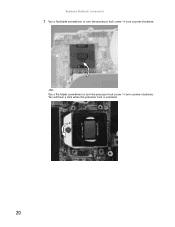
You will hear a click when the processor lock is unlocked. 20 Replacing Notebook Components 3 Use a flat-blade screwdriver to turn the processor lock screw ¼-turn counter-clockwise. -ORUse a flat-blade screwdriver to turn the processor lock screw ½-turn counter-clockwise.
You will hear a click when the processor lock is unlocked. 20 Replacing Notebook Components 3 Use a flat-blade screwdriver to turn the processor lock screw ¼-turn counter-clockwise. -ORUse a flat-blade screwdriver to turn the processor lock screw ½-turn counter-clockwise.
8511725 - Gateway Service Guide
Page 26
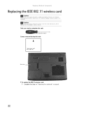
... 802.11 wireless card: 1 Complete the steps in "Preparing the notebook" on page 6. 22 Replacing Notebook Components Replacing the IEEE 802.11 wireless card Caution By law, only approved wireless modules provided by Gateway, or a Gateway authorized representative, explicitly for this Gateway notebook may be in this notebook. Tools you need to complete this task: Phillips #0 screwdriver...
... 802.11 wireless card: 1 Complete the steps in "Preparing the notebook" on page 6. 22 Replacing Notebook Components Replacing the IEEE 802.11 wireless card Caution By law, only approved wireless modules provided by Gateway, or a Gateway authorized representative, explicitly for this Gateway notebook may be in this notebook. Tools you need to complete this task: Phillips #0 screwdriver...
8511725 - Gateway Service Guide
Page 28
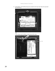
Replacing Notebook Components 5 If the wireless card is held by clips, press outward on the clip at each side of the card until the card tilts up. -ORIf the wireless card is held by a screw, remove the screw. Screw 24
Replacing Notebook Components 5 If the wireless card is held by clips, press outward on the clip at each side of the card until the card tilts up. -ORIf the wireless card is held by a screw, remove the screw. Screw 24


