Gateway ML6232 Memory
Related Manual Pages


Similar Questions


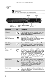
Sd Memory Card Slot
i wanted to know where is the SD memory card slot, I can't seem to find it.
i wanted to know where is the SD memory card slot, I can't seem to find it.
(Posted by Hueraztlan 11 years ago)

Related Terms
The following terms were also used when searching for Gateway ML6232 Memory:- gateway ml6232
- gateway ml6232 laptop
- ml6232 gateway
- gateway ml6232 notebook
- ml6232 notebook
- ml6232 laptop
- ml6232 drivers
- gateway ml6232 memory
- ml6232 dc jack
- ml6232 review
- gateway ml6232 dc jack
- gateway ml6232 review
- ml6232 parts
- ml6232 motherboard
- ml6232 memory
- ml6232 specs
- ml6232 battery
- ml6232 specifications
- gateway ml6232 drivers
- gateway ml6232 disassembly
- ml6232 ac adapter
- ml6232 keyboard
- ml6232 power supply
- gateway ml6232 manual
- ml6232 charger
- ml6232 manual
- ml6232 xp drivers
- ml6232 optical drive
- ml6232 laptop fan noise
- ml6232 hard drives
- ml6232 hard drive
- ml6232 gateway wireless card location
- ml6232 gateway specs
- ml6232 gateway notebook
- ml6232 fan
- ml6232 dvd player
- ml6232 recovery
- model ml6232
- ml6232 wireless driver
- ml6232 windows 7 drivers
- ml6232 will not run on ac
- ml6232 service manual
- ml6232 screen is blank
- ml6232 restore
- ml6232 repair
- ml6232 laptop specs
- ml6232 ram
- ml6232 power cord
- ml6232 power adapter
- ml6232 over heating
- ml6232 cd/dvd drive
- ml6232 notebook hard drive
- ml6232 memory upgrade
- ml6232 lcd
- gateway ml6232 keyboard
- gateway ml6232 power supply
- gateway ml6232 power cord
- gateway ml6232 parts
- gateway ml6232 notebook hard drive
- gateway ml6232 motherboard
- gateway ml6232 memory upgrade
- gateway ml6232 lcd
- gateway ml6232 laptop specs
- gateway ml6232 laptop fan noise
- gateway ml6232 ram
- gateway ml6232 hard drives
- gateway ml6232 hard drive
- gateway ml6232 drivers win xp
- gateway ml6232 charger
- gateway ml6232 cd/dvd drive
- gateway ml6232 bios
- gateway ml6232 battery
- gateway ml6232 adapter
- gateway ml6232 ac adapter
- gateway ml6232 wireless driver
- ml6232 dvd
- ml6232 drivers win xp
- ml6232 disassembly
- ml6232 case
- ml6232 bios
- ml6232 adapter
- ml6232
- gateway model ml6232
- gateway ml6232 xp drivers
- ml6232 dvd drive
- gateway ml6232 windows 7 drivers
- gateway ml6232 will not run on ac
- gateway ml6232 specs
- gateway ml6232 specifications
- gateway ml6232 service manual
- gateway ml6232 screen is blank
- gateway ml6232 restore
- gateway ml6232 repair
- gateway ml6232 recovery