User manual
Page 6
... 13 Install other Internal Connectors 14 Jumpers 18 OnBoard Button 19 OnBoard Debug LED 20 Chapter 3 BIOS Setup Enter BIOS Setup 22 Main ...23 Advanced 25 Chipset...32 Boot...37 Security 38 Save & Exit 39 Quantum BIOS 41 Chapter 4 CD Instruction Utility CD content 49 Install driver and utility 50 Aegis Panel Main...
... 13 Install other Internal Connectors 14 Jumpers 18 OnBoard Button 19 OnBoard Debug LED 20 Chapter 3 BIOS Setup Enter BIOS Setup 22 Main ...23 Advanced 25 Chipset...32 Boot...37 Security 38 Save & Exit 39 Quantum BIOS 41 Chapter 4 CD Instruction Utility CD content 49 Install driver and utility 50 Aegis Panel Main...

User manual
Page 7
CrossFireTM Technology 103 Technical Support : Website : http://www.foxconnchannel.com Support Support Website : http://www.foxconnsupport.com Worldwide online contact Support : http://www.foxconnsupport.com/inquiry.aspx CPU Support List : http://www.foxconnsupport.com/cpusupportlist.aspx Memory, VGA Compatibility List : http://www.foxconnsupport.com/complist.aspx BIOS Configuration 66 Create RAID in BIOS 66 Install a New Windows XP 95 Existing Windows XP with RAID built as data storage 99 Appendix -
CrossFireTM Technology 103 Technical Support : Website : http://www.foxconnchannel.com Support Support Website : http://www.foxconnsupport.com Worldwide online contact Support : http://www.foxconnsupport.com/inquiry.aspx CPU Support List : http://www.foxconnsupport.com/cpusupportlist.aspx Memory, VGA Compatibility List : http://www.foxconnsupport.com/complist.aspx BIOS Configuration 66 Create RAID in BIOS 66 Install a New Windows XP 95 Existing Windows XP with RAID built as data storage 99 Appendix -
User manual
Page 15
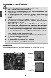
... optimized for the peripherals. It is not recommended that supports HT Technology and has it does not meet the standard requirements for HT Technology ■ A BIOS that the system bus frequency be inserted if oriented incorrectly. (Or you begin to prevent hardware damage. ■ Locate the pin one of the CPU...
... optimized for the peripherals. It is not recommended that supports HT Technology and has it does not meet the standard requirements for HT Technology ■ A BIOS that the system bus frequency be inserted if oriented incorrectly. (Or you begin to prevent hardware damage. ■ Locate the pin one of the CPU...

User manual
Page 18
... is recommended that memory of DIMM modules are : DIMM1 DIMM2 DIMM3 Single Channel DS/SS - - Dual Channel - - DS/SS DS/SS ! It is installed, the BIOS will automatically check the memory in only one direction. DS/SS - DS/SS - Single Channel - CAUTION 2 2-2 Install the Memory ! CAUTION 11 11
... is recommended that memory of DIMM modules are : DIMM1 DIMM2 DIMM3 Single Channel DS/SS - - Dual Channel - - DS/SS DS/SS ! It is installed, the BIOS will automatically check the memory in only one direction. DS/SS - DS/SS - Single Channel - CAUTION 2 2-2 Install the Memory ! CAUTION 11 11
User manual
Page 20
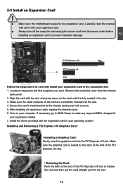
...: Push the latch at the end of the PCI Express x16 slot to prevent hardware damage. Secure the card's metal bracket to make any required BIOS changes for your computer. CAUTION 2 2-3 Install an Expansion Card ! ■ Make sure the motherboard supports the expansion card. Carefully read the manual ... before installing an expansion card to release the card and then pull the card straight up from the slot. 13 13 If necessary, go to BIOS Setup to the chassis back panel with your card. Installing and Removing a PCI Express x16 Graphics Card : • Installing a Graphics Card: Gently ...
...: Push the latch at the end of the PCI Express x16 slot to prevent hardware damage. Secure the card's metal bracket to make any required BIOS changes for your computer. CAUTION 2 2-3 Install an Expansion Card ! ■ Make sure the motherboard supports the expansion card. Carefully read the manual ... before installing an expansion card to release the card and then pull the card straight up from the slot. 13 13 If necessary, go to BIOS Setup to the chassis back panel with your card. Installing and Removing a PCI Express x16 Graphics Card : • Installing a Graphics Card: Gently ...

User manual
Page 24
2 S/PDIF Connector : SPDIF_OUT3 The connector is used for S/PDIF output. The fan speed can be controlled and monitored in "Quantum BIOS" section of the BIOS Setup. These fans can be automatically turned off after the system enters S3, S4 and S5 sleeping states. 1 GND +12V NC FAN1/2, SYS_FAN1/2/3 1 GND POWER SENSE CONTROL CPU_FAN1 17 17 SPDIF_OUT 1 GND 2 SPDIF_OUT3 Fan Connectors : CPU_FAN, FAN1/2, SYS_FAN1/2/3 There are six main fan headers on this motherboard.
2 S/PDIF Connector : SPDIF_OUT3 The connector is used for S/PDIF output. The fan speed can be controlled and monitored in "Quantum BIOS" section of the BIOS Setup. These fans can be automatically turned off after the system enters S3, S4 and S5 sleeping states. 1 GND +12V NC FAN1/2, SYS_FAN1/2/3 1 GND POWER SENSE CONTROL CPU_FAN1 17 17 SPDIF_OUT 1 GND 2 SPDIF_OUT3 Fan Connectors : CPU_FAN, FAN1/2, SYS_FAN1/2/3 There are six main fan headers on this motherboard.

User manual
Page 25
... uses CMOS RAM to short them . Put a metal object(such as a screwdriver) onto pins 1-2 to store the basic hardware information (such as BIOS data, date, time information, hardware password...etc.). For any jumper setting. The following content carefully prior to use the various functions of this motherboard by... the CMOS while the system is simply labeled as described in next chapter. The steps to configure new system as "1". 2. Go to BIOS Setup to clear CMOS data are : 1. "Closed" means placing a jumper cap on the two pins to factory default when the...
... uses CMOS RAM to short them . Put a metal object(such as a screwdriver) onto pins 1-2 to store the basic hardware information (such as BIOS data, date, time information, hardware password...etc.). For any jumper setting. The following content carefully prior to use the various functions of this motherboard by... the CMOS while the system is simply labeled as described in next chapter. The steps to configure new system as "1". 2. Go to BIOS Setup to clear CMOS data are : 1. "Closed" means placing a jumper cap on the two pins to factory default when the...

User manual
Page 26
... CLS_CMOS button to clear CMOS. ■ Push down the CLS_CMOS button and hold there for a couple of BIOS has been damaged, you are doing the BIOS recovery procedure, don't change to your bad BIOS.And then run the "FPT" reflash program. 1 (Default) 2 3 1 2 SPI 1 3 SPI ...2 BIOS_SELECT CAUTION Definition Description Function 1-2(default) Set Pin 1 and Pin 2 closed Select SPI1 (BIOS ROM 1) 2-3 Set Pin 2 and Pin 3 closed Select SPI2 (BIOS ROM 2) ! ■ Besides you can refer to the following table for a couple of seconds to clear CMOS. Then switch the jumper...
... CLS_CMOS button to clear CMOS. ■ Push down the CLS_CMOS button and hold there for a couple of BIOS has been damaged, you are doing the BIOS recovery procedure, don't change to your bad BIOS.And then run the "FPT" reflash program. 1 (Default) 2 3 1 2 SPI 1 3 SPI ...2 BIOS_SELECT CAUTION Definition Description Function 1-2(default) Set Pin 1 and Pin 2 closed Select SPI1 (BIOS ROM 1) 2-3 Set Pin 2 and Pin 3 closed Select SPI2 (BIOS ROM 2) ! ■ Besides you can refer to the following table for a couple of seconds to clear CMOS. Then switch the jumper...

User manual
Page 27
... support a clock lower than 100MHz. 2 CAUTION OC Switch Button: OC_SW1/2/3 You could press the three buttons to adjust the CPU clock directly, without to enter BIOS setup or any system resource, so there is no effect to enter the OC mode and the led lights will show "0.0". All the led lights... the OC function is 101 MHz. ■ In the OC mode, pressing the OC_SW3 button will decrease the clock by OC_SW1, the overclocking items in BIOS or software will increase 0.1 at the same time. It means the CPU current clock is controlled by 1 MHz per step. It is 100MHz(Default). ■...
... support a clock lower than 100MHz. 2 CAUTION OC Switch Button: OC_SW1/2/3 You could press the three buttons to adjust the CPU clock directly, without to enter BIOS setup or any system resource, so there is no effect to enter the OC mode and the led lights will show "0.0". All the led lights... the OC function is 101 MHz. ■ In the OC mode, pressing the OC_SW3 button will decrease the clock by OC_SW1, the overclocking items in BIOS or software will increase 0.1 at the same time. It means the CPU current clock is controlled by 1 MHz per step. It is 100MHz(Default). ■...
User manual
Page 28
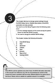
... Power On Self Test (POST) process. 2. We do not guarantee the content of the BIOS parameters are also provided. This chapter tells how to change system settings through the BIOS Setup menus. This chapter includes the following cases occur : 1. Please visit our website for...; Chipset ■ Boot ■ Security ■ Save & Exit ■ Quantum BIOS Since BIOS could be updated some other times, the BIOS information described in this manual will remain consistent with the newly released BIOS at any given time in the future. You want to change the default CMOS settings....
... Power On Self Test (POST) process. 2. We do not guarantee the content of the BIOS parameters are also provided. This chapter tells how to change system settings through the BIOS Setup menus. This chapter includes the following cases occur : 1. Please visit our website for...; Chipset ■ Boot ■ Security ■ Save & Exit ■ Quantum BIOS Since BIOS could be updated some other times, the BIOS information described in this manual will remain consistent with the newly released BIOS at any given time in the future. You want to change the default CMOS settings....

User manual
Page 29
...size, system date, time and so on the computer, when the message "Press TAB to show POST screen, DEL to key in the BIOS Setup, and we shall not be set up through this menu. You also can be responsible for your system loading is explained below: Main ...It displays the basic system configuration, such as less I /O cards installed. 3 CAUTION Enter BIOS Setup The BIOS is the communication bridge between hardware and software, correctly setting up through this menu. However, it may sometimes come out an unstable system. It...
...size, system date, time and so on the computer, when the message "Press TAB to show POST screen, DEL to key in the BIOS Setup, and we shall not be set up through this menu. You also can be responsible for your system loading is explained below: Main ...It displays the basic system configuration, such as less I /O cards installed. 3 CAUTION Enter BIOS Setup The BIOS is the communication bridge between hardware and software, correctly setting up through this menu. However, it may sometimes come out an unstable system. It...
User manual
Page 30
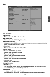
...item displays the total memory size. Main Advanced Chipset Boot Security Save & Exit Quantum BIOS BIOS Information BIOS Vendor BIOS Build Date System BIOS Version Model Name American Megatrends 12/09/2010 09:44:32 D18 Rattler Set the Date. Day-weekday from Sun. F1: General Help F2: Previous Values ... Setup Utility - Copyright (C) 2010 American Megatrends, Inc. The size is automatically displayed by BIOS (Read 23 User can check this information and discuss with the field service people if a BIOS upgrade is needed. ► Model Name This item shows the model name of this message...
...item displays the total memory size. Main Advanced Chipset Boot Security Save & Exit Quantum BIOS BIOS Information BIOS Vendor BIOS Build Date System BIOS Version Model Name American Megatrends 12/09/2010 09:44:32 D18 Rattler Set the Date. Day-weekday from Sun. F1: General Help F2: Previous Values ... Setup Utility - Copyright (C) 2010 American Megatrends, Inc. The size is automatically displayed by BIOS (Read 23 User can check this information and discuss with the field service people if a BIOS upgrade is needed. ► Model Name This item shows the model name of this message...
User manual
Page 33
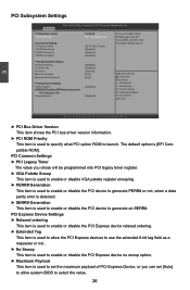
....00 [EFI Compatible ROM] [32 PCI Bus Clocks] [Disabled] [Disabled] [Disabled] In case of PCI Express Device, or you can set [Auto] to allow system BIOS to launch. The default option is used to specify what PCI Option ROM to fail Extended Synch [Disabled] → ←: Select Screen ↑ ↓: Select...
....00 [EFI Compatible ROM] [32 PCI Bus Clocks] [Disabled] [Disabled] [Disabled] In case of PCI Express Device, or you can set [Auto] to allow system BIOS to launch. The default option is used to specify what PCI Option ROM to fail Extended Synch [Disabled] → ←: Select Screen ↑ ↓: Select...
User manual
Page 34
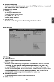
... "S1 (POS)" mode, the power is always on and computer can set the ASPM level here: [Force L0]: Force all links to L0 state. [Auto]: BIOS auto configure it means OS will automatically take care and assign which mode is the most suitable now. ► Lock Legacy Resources This item is... state when the STR function wakes.When you select "Auto", it . [Disable]: Disable the ASPM. ► Extended Synch This item is used to allow system BIOS to Hibernate(OS/S4 Sleep State). F1: General Help F2: Previous Values F3: Optimized Defaults F4: Save & Exit ESC: Exit Version 2.10.1208. ACPI Settings...
... "S1 (POS)" mode, the power is always on and computer can set the ASPM level here: [Force L0]: Force all links to L0 state. [Auto]: BIOS auto configure it means OS will automatically take care and assign which mode is the most suitable now. ► Lock Legacy Resources This item is... state when the STR function wakes.When you select "Auto", it . [Disable]: Disable the ASPM. ► Extended Synch This item is used to allow system BIOS to Hibernate(OS/S4 Sleep State). F1: General Help F2: Previous Values F3: Optimized Defaults F4: Save & Exit ESC: Exit Version 2.10.1208. ACPI Settings...
User manual
Page 35
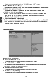
...-up Power Supply" to [Disabled] and set this item to [Enabled], only S3 state can be wake up. 3 This item determines whether to invoke VGA BIOS post on S3/STR resume. ► S4 and S5 Wake-Up Power Supply when you select [Disabled], only the power button can wake up the...
...-up Power Supply" to [Disabled] and set this item to [Enabled], only S3 state can be wake up. 3 This item determines whether to invoke VGA BIOS post on S3/STR resume. ► S4 and S5 Wake-Up Power Supply when you select [Disabled], only the power button can wake up the...

User manual
Page 37
The EHCI ownership change should be claimed by platform BIOS prior to OS initialization. ► External SATA Port (Appears when "SATA Mode" is set to [AHCI Mode]) This item is used to allow an outside ...
The EHCI ownership change should be claimed by platform BIOS prior to OS initialization. ► External SATA Port (Appears when "SATA Mode" is set to [AHCI Mode]) This item is used to allow an outside ...

User manual
Page 44
...Enabled] [Disabled] CSM16 Module Version 07.64 Option ROM Messages Interrupt 19 Capture HDD BootSector Write ZIP Emulation Type Boot Option Priorities [Force BIOS] [Disabled] [Normal] [Floppy] → ←: Select Screen ↑ ↓: Select Item Enter: Select +/-: Change Opt. Main Advanced Chipset... BBoooot t Security Save & Exit Quantum BIOS Boot Configuration Number of the CSM16 module. ► Option ROM Message This item is used to set the display mode for option ROM. ...
...Enabled] [Disabled] CSM16 Module Version 07.64 Option ROM Messages Interrupt 19 Capture HDD BootSector Write ZIP Emulation Type Boot Option Priorities [Force BIOS] [Disabled] [Normal] [Floppy] → ←: Select Screen ↑ ↓: Select Item Enter: Select +/-: Change Opt. Main Advanced Chipset... BBoooot t Security Save & Exit Quantum BIOS Boot Configuration Number of the CSM16 module. ► Option ROM Message This item is used to set the display mode for option ROM. ...
User manual
Page 45
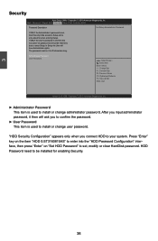
... HDD to be installed for when entering Setup. 3 Security Aptio Setup Utility - Copyright (C) 2010 American Megatrends, Inc. Main Advanced Chipset Boot SSeeccuurriittyy Save & Exit Quantum BIOS Password Description Set Setup Administrator Password If ONLY the Administrator's password is only asked for enabling Security. 38 HDD Password need to your system.
... HDD to be installed for when entering Setup. 3 Security Aptio Setup Utility - Copyright (C) 2010 American Megatrends, Inc. Main Advanced Chipset Boot SSeeccuurriittyy Save & Exit Quantum BIOS Password Description Set Setup Administrator Password If ONLY the Administrator's password is only asked for enabling Security. 38 HDD Password need to your system.

User manual
Page 46
Main Advanced Chipset Boot Security SSaavvee && EExxiitt Quantum BIOS Save Changes and Exit Discard Changes and Exit Save Changes and Reset Discard Changes and Reset Exit s ystem s etup a fter s aving the c hanges. Select [Yes] ... Megatrends, Inc. Copyright (C) 2010 American Megatrends, Inc. ► Save Changes and Exit If you select this motherboard. Always load the Optimal defaults after updating the BIOS or after clearing the CMOS values. Select this option and press , a message will pop out a dialogue box to the main menu. ► Discard Changes If...
Main Advanced Chipset Boot Security SSaavvee && EExxiitt Quantum BIOS Save Changes and Exit Discard Changes and Exit Save Changes and Reset Discard Changes and Reset Exit s ystem s etup a fter s aving the c hanges. Select [Yes] ... Megatrends, Inc. Copyright (C) 2010 American Megatrends, Inc. ► Save Changes and Exit If you select this motherboard. Always load the Optimal defaults after updating the BIOS or after clearing the CMOS values. Select this option and press , a message will pop out a dialogue box to the main menu. ► Discard Changes If...

User manual
Page 47
... changes done so far as user defaults, select [No] or to return to the main menu. ► Restore User Defaults If you select this default, BIOS have set cannot be displayed in the screen. By this option and press , a message will be set the optimal performance parameters of system components. But...
... changes done so far as user defaults, select [No] or to return to the main menu. ► Restore User Defaults If you select this default, BIOS have set cannot be displayed in the screen. By this option and press , a message will be set the optimal performance parameters of system components. But...


