User manual
Page 6
... Expansion Card 13 Install other Internal Connectors 14 Jumpers 18 OnBoard Button 19 OnBoard Debug LED 20 Chapter 3 BIOS Setup Enter BIOS Setup 22 Main ...23 Advanced 25 Chipset...32 Boot...37 Security 38 Save & Exit 39 Quantum BIOS 41 Chapter 4 CD Instruction Utility CD content 49 Install driver and utility 50 Aegis Panel Main Page 52 HW Monitor 53 Overclocking 55 Configuration 55 FOX LOGO 56 FOX DMI 57 Browser Configuration Utility 58 Chapter 5 RAID Configuration RAID Configuration Introduction 61 Intel® Matrix Storage...
... Expansion Card 13 Install other Internal Connectors 14 Jumpers 18 OnBoard Button 19 OnBoard Debug LED 20 Chapter 3 BIOS Setup Enter BIOS Setup 22 Main ...23 Advanced 25 Chipset...32 Boot...37 Security 38 Save & Exit 39 Quantum BIOS 41 Chapter 4 CD Instruction Utility CD content 49 Install driver and utility 50 Aegis Panel Main Page 52 HW Monitor 53 Overclocking 55 Configuration 55 FOX LOGO 56 FOX DMI 57 Browser Configuration Utility 58 Chapter 5 RAID Configuration RAID Configuration Introduction 61 Intel® Matrix Storage...

User manual
Page 14
... Memory ■ Install an Expansion Card ■ Install other Internal Connectors ■ Jumpers ■ OnBoard Button ■ OnBoard Debug LED Please visit the following website for more supporting information about your motherboard. This chapter introduces the hardware installation process, including the installation of the CPU, memory, power supply, slots, pin headers and the mounting of these modules. Please refer to the motherboard layout prior to any installation and read the contents in this chapter carefully. CPU Support List...
... Memory ■ Install an Expansion Card ■ Install other Internal Connectors ■ Jumpers ■ OnBoard Button ■ OnBoard Debug LED Please visit the following website for more supporting information about your motherboard. This chapter introduces the hardware installation process, including the installation of the CPU, memory, power supply, slots, pin headers and the mounting of these modules. Please refer to the motherboard layout prior to any installation and read the contents in this chapter carefully. CPU Support List...
User manual
Page 20
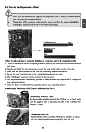
... manual that supports your expansion card in your expansion card. ■ Always turn off the computer and unplug the power cord from the power outlet before installing an expansion card to make any required BIOS changes for your computer. If necessary, go to BIOS Setup to prevent hardware damage. After installing all expansion cards, replace the chassis cover. 6. Installing and Removing a PCI Express x16 Graphics Card : • Installing a Graphics Card: Gently insert the graphics card into the slot. 4. PCI Express x16 PCI Express...
... manual that supports your expansion card in your expansion card. ■ Always turn off the computer and unplug the power cord from the power outlet before installing an expansion card to make any required BIOS changes for your computer. If necessary, go to BIOS Setup to prevent hardware damage. After installing all expansion cards, replace the chassis cover. 6. Installing and Removing a PCI Express x16 Graphics Card : • Installing a Graphics Card: Gently insert the graphics card into the slot. 4. PCI Express x16 PCI Express...

User manual
Page 23
... power button on the front panel of the hard disks. When the system gets into sleep mode (S1) , the LED is pressed. Power Switch Connector (PWR-SW) Connect to the Reset switch on the front panel of the chassis. PWR-LED - Power LED Connector (PWR-LED) Connect to be connected to the chassis front panel IDE indicator LED. This 2-pin connector is directional with +/- Speaker Connector : SPEAKER The speaker connector is used to connect speaker of the chassis. 1394a Connector : F_1394 The 1394a expansion cable can be turned on . Push this switch...
... power button on the front panel of the hard disks. When the system gets into sleep mode (S1) , the LED is pressed. Power Switch Connector (PWR-SW) Connect to the Reset switch on the front panel of the chassis. PWR-LED - Power LED Connector (PWR-LED) Connect to be connected to the chassis front panel IDE indicator LED. This 2-pin connector is directional with +/- Speaker Connector : SPEAKER The speaker connector is used to connect speaker of the chassis. 1394a Connector : F_1394 The 1394a expansion cable can be turned on . Push this switch...

User manual
Page 25
... Set Pin 1 and Pin 2 closed Set Pin 2 and Pin 3 closed Clear CMOS Jumper: CLR_CMOS The motherboard uses CMOS RAM to configure new system as "1". 2. Turn off the computer, unplug the power cord from the power outlet. 2. Go to BIOS Setup to store the basic hardware information (such as a screwdriver) onto pins 1-2 to modifying any jumper on this manual, pin 1 is turned on the two pins to leave the Pins 1-2 open. 4. WARNING! 1 Clear 2 Normal 1 (Default) 2 CLR_CMOS ■ Disconnect the power cable...
... Set Pin 1 and Pin 2 closed Set Pin 2 and Pin 3 closed Clear CMOS Jumper: CLR_CMOS The motherboard uses CMOS RAM to configure new system as "1". 2. Turn off the computer, unplug the power cord from the power outlet. 2. Go to BIOS Setup to store the basic hardware information (such as a screwdriver) onto pins 1-2 to modifying any jumper on this manual, pin 1 is turned on the two pins to leave the Pins 1-2 open. 4. WARNING! 1 Clear 2 Normal 1 (Default) 2 CLR_CMOS ■ Disconnect the power cable...

User manual
Page 29
... password before boot or access to optimal default may offer better performance in some ways (such as CPU Name, memory size, system date, time and so on the computer, when the message "Press TAB to show POST screen, DEL to enter SETUP" appears at the bottom of your computer. If you set up through this menu. However, it may cause problem if you to key...
... password before boot or access to optimal default may offer better performance in some ways (such as CPU Name, memory size, system date, time and so on the computer, when the message "Press TAB to show POST screen, DEL to enter SETUP" appears at the bottom of your computer. If you set up through this menu. However, it may cause problem if you to key...

User manual
Page 32
...Settings/Onboard Device/SATA Configuration/Thermal Configuration/USB Configuration/CMOS Press [Enter] to go to [LPC Bus] ► PCI Subsystem Settings ► ACPI Settings ► Onboard Device ► SATA Configuration ► USB Configuration ► CMOS → ←: Select Screen ↑ ↓: Select Item Enter: Select +/-: Change Opt. F1: General Help F2: Previous Values F3: Optimized Defaults F4: Save & Exit ESC: Exit Version 2.10.1208. Legacy OpROM Support ► Launch LAN 1/2 PXE OpROM This item is used to enable or disable boot option for legacy network...
...Settings/Onboard Device/SATA Configuration/Thermal Configuration/USB Configuration/CMOS Press [Enter] to go to [LPC Bus] ► PCI Subsystem Settings ► ACPI Settings ► Onboard Device ► SATA Configuration ► USB Configuration ► CMOS → ←: Select Screen ↑ ↓: Select Item Enter: Select +/-: Change Opt. F1: General Help F2: Previous Values F3: Optimized Defaults F4: Save & Exit ESC: Exit Version 2.10.1208. Legacy OpROM Support ► Launch LAN 1/2 PXE OpROM This item is used to enable or disable boot option for legacy network...
User manual
Page 33
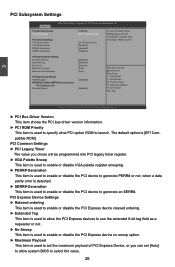
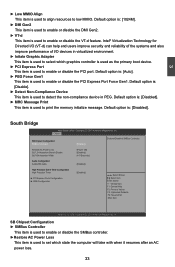
... select the value. 26 The default option is used to specify what PCI Option ROM to generate an SERR#. PCI Subsystem Settings Advanced PCI Bus Driver Version PCI ROM Priority PCI Common Settings PCI Latency Timer VGA Palette Snoop PERR# Generation SERR# Generation Aptio Setup Utility - Copyright (C) 2010 American Megatrends, Inc. V 2.03.00 [EFI Compatible ROM] [32 PCI Bus Clocks] [Disabled] [Disabled] [Disabled] In case of PCI Express Device, or you can set [Auto] to allow the PCI Express devices to use the extended 8-bit tag field as a requester...
... select the value. 26 The default option is used to specify what PCI Option ROM to generate an SERR#. PCI Subsystem Settings Advanced PCI Bus Driver Version PCI ROM Priority PCI Common Settings PCI Latency Timer VGA Palette Snoop PERR# Generation SERR# Generation Aptio Setup Utility - Copyright (C) 2010 American Megatrends, Inc. V 2.03.00 [EFI Compatible ROM] [32 PCI Bus Clocks] [Disabled] [Disabled] [Disabled] In case of PCI Express Device, or you can set [Auto] to allow the PCI Express devices to use the extended 8-bit tag field as a requester...
User manual
Page 34
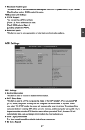
...: Optimized Defaults F4: Save & Exit ESC: Exit Version 2.10.1208. When you select "S1 (POS)" mode, the power is used to allow system BIOS to Hibernate(OS/S4 Sleep State). When you select "Auto", it . [Disable]: Disable the ASPM. ► Extended Synch This item is used to set [Auto] to allow generation of extended synchronization patterns. 3 ACPI Settings Advanced Aptio Setup Utility - PCI Express Link Settings ► ASPM Support You can...
...: Optimized Defaults F4: Save & Exit ESC: Exit Version 2.10.1208. When you select "S1 (POS)" mode, the power is used to allow system BIOS to Hibernate(OS/S4 Sleep State). When you select "Auto", it . [Disable]: Disable the ASPM. ► Extended Synch This item is used to set [Auto] to allow generation of extended synchronization patterns. 3 ACPI Settings Advanced Aptio Setup Utility - PCI Express Link Settings ► ASPM Support You can...
User manual
Page 35
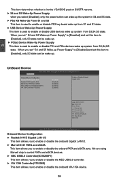
... Controller(D720200F1) [Enabled] VIA 1394 Controller(VT6308S) [Enabled] Enable or Disable Onboard Gigabit LAN 1 → ←: Select Screen ↑ ↓: Select Item Enter: Select +/-: Change Opt. F1: General Help F2: Previous Values F3: Optimized Defaults F4: Save & Exit ESC: Exit Version 2.10.1208. 3 This item determines whether to invoke VGA BIOS post on S3/STR resume. ► S4 and S5 Wake-Up Power Supply when you select [Disabled], only the power button...
... Controller(D720200F1) [Enabled] VIA 1394 Controller(VT6308S) [Enabled] Enable or Disable Onboard Gigabit LAN 1 → ←: Select Screen ↑ ↓: Select Item Enter: Select +/-: Change Opt. F1: General Help F2: Previous Values F3: Optimized Defaults F4: Save & Exit ESC: Exit Version 2.10.1208. 3 This item determines whether to invoke VGA BIOS post on S3/STR resume. ► S4 and S5 Wake-Up Power Supply when you select [Disabled], only the power button...

User manual
Page 36
.... This configures the SATA ports to [IDE Mode]) Serial-ATA Controller 0 are the SATA ports 5,6 of the ASP bit (bit 27). ► Serial-ATA Controller 0 (Appears when "SATA Mode" is set to get its specification. When enabled, the SATA controller will aggressively enter a lower link power state (partial or slumber) based upon the setting of the motherboard. SATA Configuration Advanced Aptio Setup Utility - F1: General Help F2: Previous Values F3: Optimized Defaults F4: Save & Exit ESC: Exit Version 2.10.1208...
.... This configures the SATA ports to [IDE Mode]) Serial-ATA Controller 0 are the SATA ports 5,6 of the ASP bit (bit 27). ► Serial-ATA Controller 0 (Appears when "SATA Mode" is set to get its specification. When enabled, the SATA controller will aggressively enter a lower link power state (partial or slumber) based upon the setting of the motherboard. SATA Configuration Advanced Aptio Setup Utility - F1: General Help F2: Previous Values F3: Optimized Defaults F4: Save & Exit ESC: Exit Version 2.10.1208...

User manual
Page 37
... set to [AHCI Mode]) This item is set to allow an outside the box connection of up delay [20 sec] [20 sec] [Auto] → ←: Select Screen ↑ ↓: Select Item Enter: Select +/-: Change Opt. The default option is loaded by EHCI driver. F1: General Help F2: Previous Values F3: Optimized Defaults F4: Save & Exit ESC: Exit Version 2.10.1208. Copyright (C) 2010 American Megatrends, Inc. [Enabled] [Disabled] Enables legacy USB support...
... set to [AHCI Mode]) This item is set to allow an outside the box connection of up delay [20 sec] [20 sec] [Auto] → ←: Select Screen ↑ ↓: Select Item Enter: Select +/-: Change Opt. The default option is loaded by EHCI driver. F1: General Help F2: Previous Values F3: Optimized Defaults F4: Save & Exit ESC: Exit Version 2.10.1208. Copyright (C) 2010 American Megatrends, Inc. [Enabled] [Disabled] Enables legacy USB support...
User manual
Page 40
... [Power Off] [Enabled] [4-5 Seconds] Audio Configuration Azalia HD Audio [Enabled] High Precision Event Timer Configuration High Precision Timer ► PCI Express Ports Configuration ► USB Configuration [Enabled] → ←: Select Screen ↑ ↓: Select Item Enter: Select +/-: Change Opt. Chipset SB Chipset Configuration SMBus Controller [Enabled] Enabled/Disabled SMBus Controller. F1: General Help F2: Previous Values F3: Optimized Defaults F4: Save & Exit ESC: Exit Version 2.10.1208. Default option is: [1024M]. ► DMI Gen2 This item is used to enable...
... [Power Off] [Enabled] [4-5 Seconds] Audio Configuration Azalia HD Audio [Enabled] High Precision Event Timer Configuration High Precision Timer ► PCI Express Ports Configuration ► USB Configuration [Enabled] → ←: Select Screen ↑ ↓: Select Item Enter: Select +/-: Change Opt. Chipset SB Chipset Configuration SMBus Controller [Enabled] Enabled/Disabled SMBus Controller. F1: General Help F2: Previous Values F3: Optimized Defaults F4: Save & Exit ESC: Exit Version 2.10.1208. Default option is: [1024M]. ► DMI Gen2 This item is used to enable...

User manual
Page 44
... setup activation key. 65535(0xFFFF) means indefinite waiting. ► Bootup Numlock State This item is used to wait for ZIP drives. 37 Quiet Boot Fast Boot [Enabled] [Disabled] CSM16 Module Version 07.64 Option ROM Messages Interrupt 19 Capture HDD BootSector Write ZIP Emulation Type Boot Option Priorities [Force BIOS] [Disabled] [Normal] [Floppy] → ←: Select Screen ↑ ↓: Select Item Enter: Select +/-: Change Opt. Copyright (C) 2010 American Megatrends, Inc. The defaulte setting...
... setup activation key. 65535(0xFFFF) means indefinite waiting. ► Bootup Numlock State This item is used to wait for ZIP drives. 37 Quiet Boot Fast Boot [Enabled] [Disabled] CSM16 Module Version 07.64 Option ROM Messages Interrupt 19 Capture HDD BootSector Write ZIP Emulation Type Boot Option Priorities [Force BIOS] [Disabled] [Normal] [Floppy] → ←: Select Screen ↑ ↓: Select Item Enter: Select +/-: Change Opt. Copyright (C) 2010 American Megatrends, Inc. The defaulte setting...
User manual
Page 45
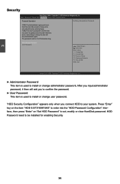
Main Advanced Chipset Boot SSeeccuurriittyy Save & Exit Quantum BIOS Password Description Set Setup Administrator Password If ONLY the Administrator's password is set, then this is only asked for enabling Security. 38 Administrator Password User Password → ←: Select Screen ↑ ↓: Select Item Enter: Select +/-: Change Opt. F1: General Help F2: Previous Values F3: Optimized Defaults F4: Save & Exit ESC: Exit Version 2.10.1208. HDD Password need to Setup and is a power on "Set HDD Password" to...
Main Advanced Chipset Boot SSeeccuurriittyy Save & Exit Quantum BIOS Password Description Set Setup Administrator Password If ONLY the Administrator's password is set, then this is only asked for enabling Security. 38 Administrator Password User Password → ←: Select Screen ↑ ↓: Select Item Enter: Select +/-: Change Opt. F1: General Help F2: Previous Values F3: Optimized Defaults F4: Save & Exit ESC: Exit Version 2.10.1208. HDD Password need to Setup and is a power on "Set HDD Password" to...
User manual
Page 49
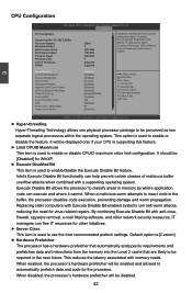
Quantum BIOQSuantum BIOS CPU Configuration Genuine Intel(R) CPU 0 @ 3.00GHz Processor Stepping Microcode Revision Max Processor Speed Min Processor Speed Processor Speed Processor Cores Intel HT Technology EMT64 206a3 8 3000 MHz 1600 MHz 2200 MHz 4 Supported Supported Enabled for Windows XP and Linux(OS optimized for Hyper-Threading Technology) and Disabled for other initiatives. ► Server Class This item is used to use the Intel recommended prefech settings. Copyright (C) 2010 American Megatrends, Inc. ► Hyper-threading...
Quantum BIOQSuantum BIOS CPU Configuration Genuine Intel(R) CPU 0 @ 3.00GHz Processor Stepping Microcode Revision Max Processor Speed Min Processor Speed Processor Speed Processor Cores Intel HT Technology EMT64 206a3 8 3000 MHz 1600 MHz 2200 MHz 4 Supported Supported Enabled for Windows XP and Linux(OS optimized for Hyper-Threading Technology) and Disabled for other initiatives. ► Server Class This item is used to use the Intel recommended prefech settings. Copyright (C) 2010 American Megatrends, Inc. ► Hyper-threading...
User manual
Page 50
... supporting this item. ! This item will be met, including CPU, chipset, motherboard, BIOS and operation system. Please refer to Intel website for a 64-byte cache line. CAUTION 43 When disabled, the processor will retrieve the currently requested cache line, as well as multiple "virtual" systems. Vanderpool Technology can select the EIST (Processor Power Management, PPM) through this feature and the setting is used...
... supporting this item. ! This item will be met, including CPU, chipset, motherboard, BIOS and operation system. Please refer to Intel website for a 64-byte cache line. CAUTION 43 When disabled, the processor will retrieve the currently requested cache line, as well as multiple "virtual" systems. Vanderpool Technology can select the EIST (Processor Power Management, PPM) through this feature and the setting is used...
User manual
Page 56
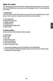
... into your DVD-ROM drive, and the main menu will not show in Windows XP operation system, but it will be displayed on your PC screen to guide you how to [RAID Mode]. *2 : The item will appear in Windows Vista and Windows 7 operation system. 49 49 USB 3.0 Driver 2. AEGIS PANEL B. A. FOX LOGO C. Browser Configuration Utility *1 : This item will be displayed only when "SATA Mode" is set to install. 1. Intel RAID Driver*1 E. Intel Management Engine Driver F. Microsoft...
... into your DVD-ROM drive, and the main menu will not show in Windows XP operation system, but it will be displayed on your PC screen to guide you how to [RAID Mode]. *2 : The item will appear in Windows Vista and Windows 7 operation system. 49 49 USB 3.0 Driver 2. AEGIS PANEL B. A. FOX LOGO C. Browser Configuration Utility *1 : This item will be displayed only when "SATA Mode" is set to install. 1. Intel RAID Driver*1 E. Intel Management Engine Driver F. Microsoft...
User manual
Page 69
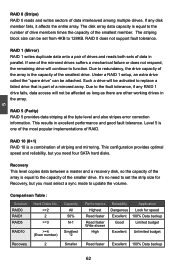
... to replace a failed drive that is equal to the capacity of data interleaved among multiple drives. RAID 5 (Parity) RAID 5 provides data striping at the byte level and also stripes error correction information. It's no need to 128KB. 5 RAID 0 (Stripe) RAID 0 reads and writes sectors of the smaller drive. The striping block size can be set from 4KB to set the strip size for speed...
... to replace a failed drive that is equal to the capacity of data interleaved among multiple drives. RAID 5 (Parity) RAID 5 provides data striping at the byte level and also stripes error correction information. It's no need to 128KB. 5 RAID 0 (Stripe) RAID 0 reads and writes sectors of the smaller drive. The striping block size can be set from 4KB to set the strip size for speed...

User manual
Page 103
... following mass storage device(s): * To specify additional SCSI adapters, CD-ROM drivers, or special disk controllers for use with Windows, press ENTER. S=Specify Additional Device ENTER=Continue F3=Exit 6. It will load support for which you to continue the specific driver installation. Press after it is done. 5 Windows Setup Please insert the disk labeled manufacturer-supplied hardware support disk into you do not want to manually specify an adapter. After some files are copied...
... following mass storage device(s): * To specify additional SCSI adapters, CD-ROM drivers, or special disk controllers for use with Windows, press ENTER. S=Specify Additional Device ENTER=Continue F3=Exit 6. It will load support for which you to continue the specific driver installation. Press after it is done. 5 Windows Setup Please insert the disk labeled manufacturer-supplied hardware support disk into you do not want to manually specify an adapter. After some files are copied...


