User manual
Page 5
... any installation steps or have a problem related to get the best performance. ■ Before turning on the overclocking capac- Please carefully read the following procedures to install your computer : ■ It is recommended to your CPU is a PCI Express x16 graphics card installed in serious damage to unplug the AC power cord from the power supply outlet. Normally it comes out as a motherboard, CPU or memory. ■...
... any installation steps or have a problem related to get the best performance. ■ Before turning on the overclocking capac- Please carefully read the following procedures to install your computer : ■ It is recommended to your CPU is a PCI Express x16 graphics card installed in serious damage to unplug the AC power cord from the power supply outlet. Normally it comes out as a motherboard, CPU or memory. ■...

User manual
Page 9
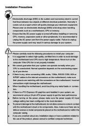
....aspx Chipset Intel® P67 Memory 4 x 240-pin DDR3 DIMMs Support up to 32GB of system memory Dual channel DDR3 1800(oc*)/1600(oc*)/1333/1066 MHz architecture (oc*: Overclocking) Expansion Slots 2 x PCI Express x16 slots 3 x PCI Express x1 slots 2 x PCI slots VGA Intel Integrated GF Storage 1 x IDE connector (P67A-S) 4 x SATA 2.0 connectors 300MB/s data transfer rate 2 x SATA 3.0 connectors 600MB/s data transfer rate 2 x eSATA ports Support RAID 0, 1, 5,10, Recovery Support hot plug and NCQ (Native Command Queuing ) LAN Realtek 8111E Audio Realtek...
....aspx Chipset Intel® P67 Memory 4 x 240-pin DDR3 DIMMs Support up to 32GB of system memory Dual channel DDR3 1800(oc*)/1600(oc*)/1333/1066 MHz architecture (oc*: Overclocking) Expansion Slots 2 x PCI Express x16 slots 3 x PCI Express x1 slots 2 x PCI slots VGA Intel Integrated GF Storage 1 x IDE connector (P67A-S) 4 x SATA 2.0 connectors 300MB/s data transfer rate 2 x SATA 3.0 connectors 600MB/s data transfer rate 2 x eSATA ports Support RAID 0, 1, 5,10, Recovery Support hot plug and NCQ (Native Command Queuing ) LAN Realtek 8111E Audio Realtek...
User manual
Page 10
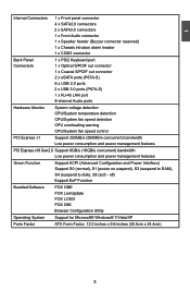
... Audio connector 1 x Speaker header (Buzzer connector reserved) 1 x Chassis intrusion alarm header 1 x COM1 connector Back Panel 1 x PS/2 Keyboard port Connectors 1 x Optical S/PDIF out connector 1 x Coaxial S/PDIF out connector 2 x eSATA ports (P67A-S) 6 x USB 2.0 ports 2 x USB 3.0 ports (P67A-S) 1 x RJ-45 LAN port 8-channel Audio ports Hardware Monitor System voltage detection CPU/System temperature detection CPU/System fan speed detection CPU overheating warning CPU/System fan speed control PCI Express x1 Support 250MB/s (500MB/s concurrent) bandwidth Low power...
... Audio connector 1 x Speaker header (Buzzer connector reserved) 1 x Chassis intrusion alarm header 1 x COM1 connector Back Panel 1 x PS/2 Keyboard port Connectors 1 x Optical S/PDIF out connector 1 x Coaxial S/PDIF out connector 2 x eSATA ports (P67A-S) 6 x USB 2.0 ports 2 x USB 3.0 ports (P67A-S) 1 x RJ-45 LAN port 8-channel Audio ports Hardware Monitor System voltage detection CPU/System temperature detection CPU/System fan speed detection CPU overheating warning CPU/System fan speed control PCI Express x1 Support 250MB/s (500MB/s concurrent) bandwidth Low power...
User manual
Page 14
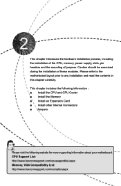
... the installation of the CPU, memory, power supply, slots, pin headers and the mounting of these modules. Caution should be exercised during the installation of jumpers. This chapter includes the following information : ■ Install the CPU and CPU Cooler ■ Install the Memory ■ Install an Expansion Card ■ Install other Internal Connectors ■ Jumpers Please visit the following website for more supporting information about your motherboard. CPU Support List: http://www.foxconnsupport.com/cpusupportlist.aspx Memory, VGA Compatibility List...
... the installation of the CPU, memory, power supply, slots, pin headers and the mounting of these modules. Caution should be exercised during the installation of jumpers. This chapter includes the following information : ■ Install the CPU and CPU Cooler ■ Install the Memory ■ Install an Expansion Card ■ Install other Internal Connectors ■ Jumpers Please visit the following website for more supporting information about your motherboard. CPU Support List: http://www.foxconnsupport.com/cpusupportlist.aspx Memory, VGA Compatibility List...
User manual
Page 20
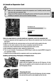
... expansion card to the chassis back panel with the expansion card in the slot. 3. After installing all expansion cards, replace the chassis cover. 6. Installing and Removing a PCI Express x16 Graphics Card : • Installing a Graphics Card: Gently insert the graphics card into the slot. 4. Make sure the graphics card is fully seated in your expansion card. ■ Always turn off the computer and unplug the power cord from the slot. 13 13 Carefully read the manual that supports your computer. Locate...
... expansion card to the chassis back panel with the expansion card in the slot. 3. After installing all expansion cards, replace the chassis cover. 6. Installing and Removing a PCI Express x16 Graphics Card : • Installing a Graphics Card: Gently insert the graphics card into the slot. 4. Make sure the graphics card is fully seated in your expansion card. ■ Always turn off the computer and unplug the power cord from the slot. 13 13 Carefully read the manual that supports your computer. Locate...
User manual
Page 22
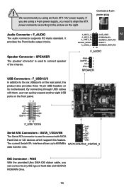
Connect a 4-pin power plug Audio Connector : F_AUDIO The audio connector supports HD Audio standard. Speaker Connector : SPEAKER The speaker connector is used to connect speaker of the chassis. 12 A_MIC2_L AUD_GND A_MIC2_R A_LINE2_R PRESENCEJ SENSE1_RETURN SENSE_SEND EMPTY A_LINE2_L SENSE2_RETURN 9 10 F_AUDIO PWR 1 EMPTY 2 NC 3 SPKJ 4 SPEAKER USB Connectors : F_USB1/2/3 In addition to any IDE type of hard disk and CD/DVD ROM/RW drive. 15 15 CAUTION 2 ! GND RXRX+ GND The current Serial ATA interface allows up to the picture on...
Connect a 4-pin power plug Audio Connector : F_AUDIO The audio connector supports HD Audio standard. Speaker Connector : SPEAKER The speaker connector is used to connect speaker of the chassis. 12 A_MIC2_L AUD_GND A_MIC2_R A_LINE2_R PRESENCEJ SENSE1_RETURN SENSE_SEND EMPTY A_LINE2_L SENSE2_RETURN 9 10 F_AUDIO PWR 1 EMPTY 2 NC 3 SPKJ 4 SPEAKER USB Connectors : F_USB1/2/3 In addition to any IDE type of hard disk and CD/DVD ROM/RW drive. 15 15 CAUTION 2 ! GND RXRX+ GND The current Serial ATA interface allows up to the picture on...
User manual
Page 23
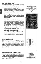
... 2-pin connector is blinking; sign. These fans can be automatically turned off rather than using the power supply button. 12 + + HDD-LED - When the system is off. Push this switch allows the system to be turned on this motherboard. Hard Disk LED Connector (HDD-LED) Connect to the power button on . It indicates the active status of the chassis. sign. User must purchase another RS232 cable with a 9-pin D-sub connector at one connector for legacy compatibility. pin female connector to connect with COM1 connector...
... 2-pin connector is blinking; sign. These fans can be automatically turned off rather than using the power supply button. 12 + + HDD-LED - When the system is off. Push this switch allows the system to be turned on this motherboard. Hard Disk LED Connector (HDD-LED) Connect to the power button on . It indicates the active status of the chassis. sign. User must purchase another RS232 cable with a 9-pin D-sub connector at one connector for legacy compatibility. pin female connector to connect with COM1 connector...
User manual
Page 25
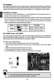
..., users can change the jumper settings on . 5. Description of the jumper settings. However, in the power cord to your computer and turn it onto pins 1-2 to store the basic hardware information (such as "1". 2. Jumper 1 Diagram 1 1 Definition 1-2 2-3 Description Set Pin 1 and Pin 2 closed Set Pin 2 and Pin 3 closed . 4. Remove jumper cap from the power outlet. 2. This will clear CMOS data. 3. Return the setting to its original with pins 2-3 closed Clear CMOS Jumper: CLR_CMOS The motherboard uses CMOS RAM to short them . Plug in this motherboard...
..., users can change the jumper settings on . 5. Description of the jumper settings. However, in the power cord to your computer and turn it onto pins 1-2 to store the basic hardware information (such as "1". 2. Jumper 1 Diagram 1 1 Definition 1-2 2-3 Description Set Pin 1 and Pin 2 closed Set Pin 2 and Pin 3 closed . 4. Remove jumper cap from the power outlet. 2. This will clear CMOS data. 3. Return the setting to its original with pins 2-3 closed Clear CMOS Jumper: CLR_CMOS The motherboard uses CMOS RAM to short them . Plug in this motherboard...
User manual
Page 26
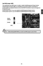
... set MFG jumper to pins 2-3, you can enable the Intel® Management Engine function. Set the jumper to pins 2-3 first. It provides latest IT management features such as Intel® AMT, that allows to enable or disable Intel® Management Engine function. Intel® Management Engine (ME) is an embedded microcontroller located in Intel chipset. 2 Intel® ME Jumper: MFG This motherboard uses MFG jumper...
... set MFG jumper to pins 2-3, you can enable the Intel® Management Engine function. Set the jumper to pins 2-3 first. It provides latest IT management features such as Intel® AMT, that allows to enable or disable Intel® Management Engine function. Intel® Management Engine (ME) is an embedded microcontroller located in Intel chipset. 2 Intel® ME Jumper: MFG This motherboard uses MFG jumper...
User manual
Page 28
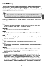
... boot device priority and enable "Quiet Boot" feature here. Chipset The values for your computer. Security The Administrator/User password can save or discard the changes and exit BIOS setup here. 21 You also can be optimized. CAUTION 3 Enter BIOS Setup The BIOS is the communication bridge between hardware and software, correctly setting up the BIOS parameters is explained below: Main It displays the basic system configuration, such as less I /O cards installed...
... boot device priority and enable "Quiet Boot" feature here. Chipset The values for your computer. Security The Administrator/User password can save or discard the changes and exit BIOS setup here. 21 You also can be optimized. CAUTION 3 Enter BIOS Setup The BIOS is the communication bridge between hardware and software, correctly setting up the BIOS parameters is explained below: Main It displays the basic system configuration, such as less I /O cards installed...

User manual
Page 32
... CPU Configuration Genuine Intel(R) CPU 0 @ 2.40GHz EMT64 Supported Processor Speed 1600 MHz CPU ID 206a2 Microcode Revision 26 Processor Cores 2 Intel HT Technology Supported C1E Support Hyper-threading Execute Disable Bit Intel Virtualization Technology CPU C6 Report Package C State limit [Enabled] [Enabled] [Enabled] [Disabled] [Enabled] [No Limit] → ← : Select Screen ↑ ↓ : Select Item Enter: Select +/-: Change Opt. It is a feature which CPU uses to run multiple operating systems and applications in memory by where application code can free...
... CPU Configuration Genuine Intel(R) CPU 0 @ 2.40GHz EMT64 Supported Processor Speed 1600 MHz CPU ID 206a2 Microcode Revision 26 Processor Cores 2 Intel HT Technology Supported C1E Support Hyper-threading Execute Disable Bit Intel Virtualization Technology CPU C6 Report Package C State limit [Enabled] [Enabled] [Enabled] [Disabled] [Enabled] [No Limit] → ← : Select Screen ↑ ↓ : Select Item Enter: Select +/-: Change Opt. It is a feature which CPU uses to run multiple operating systems and applications in memory by where application code can free...
User manual
Page 36
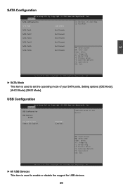
... Mode [IDE Mode] (1) IDE Mode. (2) AHCI Mode. (3) RAID Mode. Copyright (C) 2010 American Megatrends, Inc. ► SATA Mode This item is used to enable or disable the support for USB devices. 29 USB Configuration Aptio Setup Utility - Advanced USB Configuration USB Devices: 2 Hubs Enabled/Disabled All USB Devices All USB Devices Legacy USB Support [Enabled] [Enabled] → ← : Select Screen ↑ ↓ : Select Item Enter: Select +/-: Change Opt. 3 SATA Configuration Aptio Setup Utility - Setting options: [IDE Mode]; [AHCI Mode]; [RAID Mode]. SATA...
... Mode [IDE Mode] (1) IDE Mode. (2) AHCI Mode. (3) RAID Mode. Copyright (C) 2010 American Megatrends, Inc. ► SATA Mode This item is used to enable or disable the support for USB devices. 29 USB Configuration Aptio Setup Utility - Advanced USB Configuration USB Devices: 2 Hubs Enabled/Disabled All USB Devices All USB Devices Legacy USB Support [Enabled] [Enabled] → ← : Select Screen ↑ ↓ : Select Item Enter: Select +/-: Change Opt. 3 SATA Configuration Aptio Setup Utility - Setting options: [IDE Mode]; [AHCI Mode]; [RAID Mode]. SATA...
User manual
Page 37
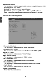
... LAN Controller Onboard LAN PXE OpROM PCI-E To PCI Brige NEC USB 3.0 Controller Marvell E-SATA Controller Marvell E-SATA OpROM [Enabled] [Disabled] [Enabled] [Enabled] [Enabled] [Enabled] Audio Configuration Azalia HD Audio [Enabled] ▶ Super IO Configuration → ← : Select Screen ↑ ↓ : Select Item Enter: Select +/-: Change Opt. Copyright (C) 2010 American Megatrends, Inc. ► Onboard LAN Controller This item is used to enable or disable the onboard LAN controller. ► Onboard LAN PXE OpROM This item is used to enable or disable boot option for onboard...
... LAN Controller Onboard LAN PXE OpROM PCI-E To PCI Brige NEC USB 3.0 Controller Marvell E-SATA Controller Marvell E-SATA OpROM [Enabled] [Disabled] [Enabled] [Enabled] [Enabled] [Enabled] Audio Configuration Azalia HD Audio [Enabled] ▶ Super IO Configuration → ← : Select Screen ↑ ↓ : Select Item Enter: Select +/-: Change Opt. Copyright (C) 2010 American Megatrends, Inc. ► Onboard LAN Controller This item is used to enable or disable the onboard LAN controller. ► Onboard LAN PXE OpROM This item is used to enable or disable boot option for onboard...
User manual
Page 47
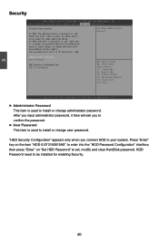
... - Main Advanced Chipset Boot Power Health Security Save & Exit Password Description If ONLY the Administrator's password is set, then this is only asked for enabling Security. 40 Set Setup Administrator Password Administrator Password User Password HDD Security Configuration: HDD 0:ST3160815AS → ← : Select Screen ↑ ↓ : Select Item Enter: Select +/-: Change Opt. Press "Enter" key on the item "HDD 0:ST3160815AS" to enter into the "HDD Password Configuration" interface, then press "Enter" on "Set HDD Password" to set , then this only limits access to...
... - Main Advanced Chipset Boot Power Health Security Save & Exit Password Description If ONLY the Administrator's password is set, then this is only asked for enabling Security. 40 Set Setup Administrator Password Administrator Password User Password HDD Security Configuration: HDD 0:ST3160815AS → ← : Select Screen ↑ ↓ : Select Item Enter: Select +/-: Change Opt. Press "Enter" key on the item "HDD 0:ST3160815AS" to enter into the "HDD Password Configuration" interface, then press "Enter" on "Set HDD Password" to set , then this only limits access to...
User manual
Page 50
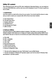
... [RAID Mode]. *2 : The item will appear in order, and you to change your system setting without being a computer literate. A. VIA HDA Audio Driver C. A. FOX DMI E. Adobe Acrobat Reader G. 4 Utility CD content This motherboard comes with one DVD, after all the drivers for your system. Intel Chipset Driver B. Software Utilities Use these options to BIOS. FOX ONE B. You should install the drivers in Windows XP operation system, but it into your DVD-ROM drive...
... [RAID Mode]. *2 : The item will appear in order, and you to change your system setting without being a computer literate. A. VIA HDA Audio Driver C. A. FOX DMI E. Adobe Acrobat Reader G. 4 Utility CD content This motherboard comes with one DVD, after all the drivers for your system. Intel Chipset Driver B. Software Utilities Use these options to BIOS. FOX ONE B. You should install the drivers in Windows XP operation system, but it into your DVD-ROM drive...
User manual
Page 79
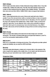
... block size can be set the strip size for speed 100% Data backup Limited budget Excellent Unlimited budget Read faster Excellent 100% Data backup 72 Under a RAID 1 setup, an extra drive called the "spare drive" can be attached. Such a drive will be affected as long as there are other working drives in the array. Level 5 is equal to update the volume. Recovery This level...
... block size can be set the strip size for speed 100% Data backup Limited budget Excellent Unlimited budget Read faster Excellent 100% Data backup 72 Under a RAID 1 setup, an extra drive called the "spare drive" can be attached. Such a drive will be affected as long as there are other working drives in the array. Level 5 is equal to update the volume. Recovery This level...
User manual
Page 101
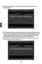
...]-(M)aster [SPACE]-(R)ecovery [ENTER]-Done 5 [↑↓]-Change [TAB]-Next [ESC]-Previous Menu [ENTER]-Select 5. It then goes to display the hard disks list for this Recovery system. 4. Intel(RIn) tMela(Rtr)ixRSatpoirdagSetoMraagneaTgeecrhonpotilongyR-OOMptvio5n.0R.0O.1M01-11I0C.0H.90R.10w3R2AID5 CCooppyyrriigghhtt((CC)) 22000033--1004 IInntteell CCoorrppoorraattiioonn.AlAl lRl RigihgthstsRReseesrevrevde.d. [ CREATE VOLUME MENU ] Name: TryRecovery RAID Level: Recovery [ SELECT DISKS ] Port Drive Model Serial # 00 HHiittaa cchhii...
...]-(M)aster [SPACE]-(R)ecovery [ENTER]-Done 5 [↑↓]-Change [TAB]-Next [ESC]-Previous Menu [ENTER]-Select 5. It then goes to display the hard disks list for this Recovery system. 4. Intel(RIn) tMela(Rtr)ixRSatpoirdagSetoMraagneaTgeecrhonpotilongyR-OOMptvio5n.0R.0O.1M01-11I0C.0H.90R.10w3R2AID5 CCooppyyrriigghhtt((CC)) 22000033--1004 IInntteell CCoorrppoorraattiioonn.AlAl lRl RigihgthstsRReseesrevrevde.d. [ CREATE VOLUME MENU ] Name: TryRecovery RAID Level: Recovery [ SELECT DISKS ] Port Drive Model Serial # 00 HHiittaa cchhii...
User manual
Page 111
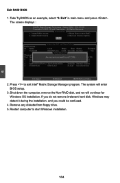
... RAID Volume 3. Recover Volume Options 5. Shut down the computer, remove the Non-RAID disk, and we will enter BIOS setup. 3. Delete RAID Volume 4. Exit [ DISK/VOLUME INFORMATION ] RAID Volume : ID Name Level Stripe Size Status Bootable 0 TryRAID5 RAID5(Parity) 64KB 149.1GB Normal Yes [ CONFIRM EXIT ] Physical Disks: Port Drive Model AreSyeoriuals#ure you could be confused. 4. The system will continue for Windows OS installation. Remove any diskette from floppy drive...
... RAID Volume 3. Recover Volume Options 5. Shut down the computer, remove the Non-RAID disk, and we will enter BIOS setup. 3. Delete RAID Volume 4. Exit [ DISK/VOLUME INFORMATION ] RAID Volume : ID Name Level Stripe Size Status Bootable 0 TryRAID5 RAID5(Parity) 64KB 149.1GB Normal Yes [ CONFIRM EXIT ] Physical Disks: Port Drive Model AreSyeoriuals#ure you could be confused. 4. The system will continue for Windows OS installation. Remove any diskette from floppy drive...
User manual
Page 112
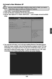
... you set the SATA Mode in BIOS to either AHCI or RAID, you need to follow these steps to "SATA: ATAPI DVD ...", save changes and exit the BIOS setup. Insert the Windows installation CD into the optical drive. 3. Main Advanced Chipset Boot Power Health Security Save & Exit Boot Configuration Bootup Numlock State [On] Select the keyboard NumLock state Quiet Boot [Enabled] CSM16 Module Version 07.63 Boot Option Priorities Boot Option #1 [SATA: ATAPI DVD ...] CD/DVD ROM Drive BBS Priorities → ← : Select Screen...
... you set the SATA Mode in BIOS to either AHCI or RAID, you need to follow these steps to "SATA: ATAPI DVD ...", save changes and exit the BIOS setup. Insert the Windows installation CD into the optical drive. 3. Main Advanced Chipset Boot Power Health Security Save & Exit Boot Configuration Bootup Numlock State [On] Select the keyboard NumLock state Quiet Boot [Enabled] CSM16 Module Version 07.63 Boot Option Priorities Boot Option #1 [SATA: ATAPI DVD ...] CD/DVD ROM Drive BBS Priorities → ← : Select Screen...
User manual
Page 113
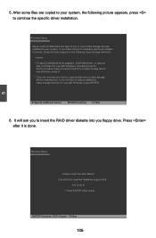
... for use with Windows, press ENTER. Windows Setup Setup could not determine the type of one or more mass storage devices installed in your system, the following mass storage device(s): * To specify additional SCSI adapters, CD-ROM drivers, or special disk controllers for which you have a device support disk from a mass storage device manufacturer, or do not have chosen to manually specify an adapter. S=Specify Additional Device ENTER=Continue F3=Exit 6. After some files are...
... for use with Windows, press ENTER. Windows Setup Setup could not determine the type of one or more mass storage devices installed in your system, the following mass storage device(s): * To specify additional SCSI adapters, CD-ROM drivers, or special disk controllers for which you have a device support disk from a mass storage device manufacturer, or do not have chosen to manually specify an adapter. S=Specify Additional Device ENTER=Continue F3=Exit 6. After some files are...


