English Manual.
Page 20
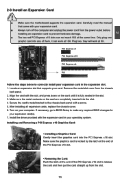
... PCI Express x16 slots can work at the same time. Carefully read the manual that supports your expansion card in your expansion card. ■ Always turn off the computer and unplug the power cord from the chassis back panel. 2. Remove the metal slot cover from the power outlet before installing an expansion card to correctly install your card. CAUTION 2 2-3 Install an Expansion Card ! ■ Make sure the motherboard supports the expansion card. Only plug one graphic card...
... PCI Express x16 slots can work at the same time. Carefully read the manual that supports your expansion card in your expansion card. ■ Always turn off the computer and unplug the power cord from the chassis back panel. 2. Remove the metal slot cover from the power outlet before installing an expansion card to correctly install your card. CAUTION 2 2-3 Install an Expansion Card ! ■ Make sure the motherboard supports the expansion card. Only plug one graphic card...

English Manual.
Page 22
... power supply. If you need to align the ATX power connector according to the eight USB ports on the front panel. 12 VCC DD+ GND EMPTY VCC DD+ GND NC 9 10 F_USB 1/2/3 Serial ATA Connectors: SATA_1/2/3/4/5/6 The Serial ATA connector is used to connect with them, user can connect to connect speaker of hard disk and CD/ DVD ROM/RW drive. By connecting through USB cables with SATA Hard Disk or CD devices which support this product also provides three 10-pin USB headers...
... power supply. If you need to align the ATX power connector according to the eight USB ports on the front panel. 12 VCC DD+ GND EMPTY VCC DD+ GND NC 9 10 F_USB 1/2/3 Serial ATA Connectors: SATA_1/2/3/4/5/6 The Serial ATA connector is used to connect with them, user can connect to connect speaker of hard disk and CD/ DVD ROM/RW drive. By connecting through USB cables with SATA Hard Disk or CD devices which support this product also provides three 10-pin USB headers...
English Manual.
Page 23
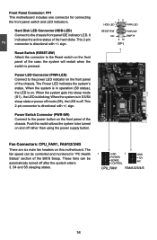
... hard disks. The fan speed can be automatically turned off rather than using the power supply button. 12 + + HDD-LED - This 2-pin connector is blinking; Reset Switch (RESET-SW) Attach the connector to the power LED indicator on the front panel of the chassis. Power Switch Connector (PWR-SW) Connect to the power button on this switch allows the system to the chassis front panel IDE indicator LED. Push this motherboard. RESET-SW PWR-SW NC EMPTY 9 10 FP1 Fan Connectors: CPU_FAN1, FAN1/2/3/4/5 There are six main fan headers...
... hard disks. The fan speed can be automatically turned off rather than using the power supply button. 12 + + HDD-LED - This 2-pin connector is blinking; Reset Switch (RESET-SW) Attach the connector to the power LED indicator on the front panel of the chassis. Power Switch Connector (PWR-SW) Connect to the power button on this switch allows the system to the chassis front panel IDE indicator LED. Push this motherboard. RESET-SW PWR-SW NC EMPTY 9 10 FP1 Fan Connectors: CPU_FAN1, FAN1/2/3/4/5 There are six main fan headers...
English Manual.
Page 25
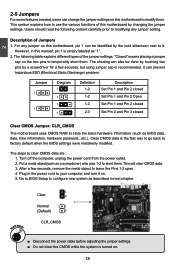
... password...etc.). However, in this motherboard to store the basic hardware information (such as described in the power cord to clear CMOS data are : 1. Jumper 1 1 Diagram 1 1 1 1 Definition 1-2 1-2 1-2 2-3 Description Set Pin 1 and Pin 2 closed Set Pin 1 and Pin 2 Open Set Pin 1 and Pin 2 closed Set Pin 2 and Pin 3 closed Clear CMOS Jumper: CLR_CMOS The motherboard uses CMOS RAM to modify them . Users should read the following table explains different types of Jumpers 1. It can change the jumper settings on this manual, pin 1 is turned on this motherboard...
... password...etc.). However, in this motherboard to store the basic hardware information (such as described in the power cord to clear CMOS data are : 1. Jumper 1 1 Diagram 1 1 1 1 Definition 1-2 1-2 1-2 2-3 Description Set Pin 1 and Pin 2 closed Set Pin 1 and Pin 2 Open Set Pin 1 and Pin 2 closed Set Pin 2 and Pin 3 closed Clear CMOS Jumper: CLR_CMOS The motherboard uses CMOS RAM to modify them . Users should read the following table explains different types of Jumpers 1. It can change the jumper settings on this manual, pin 1 is turned on this motherboard...
English Manual.
Page 28
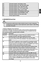
..., system chipset or option ROMs from ROM to RAM for debugging. D2 Verify the boot block checksum. Execute full memory sizing module. Re-enable CACHE. Set stack. Performs main BIOS checksum and updates recovery status accordingly. 21 21 On power sequence, but ATXPWROK cannot ready. 6.0. On power sequence, when 1.1V VTT is done including RTC and keyboard controller. Go to memory in PCI devices. 1. D4 Test base 512KB memory. Bootblock Initialization Code Checkpoints...
..., system chipset or option ROMs from ROM to RAM for debugging. D2 Verify the boot block checksum. Execute full memory sizing module. Re-enable CACHE. Set stack. Performs main BIOS checksum and updates recovery status accordingly. 21 21 On power sequence, but ATXPWROK cannot ready. 6.0. On power sequence, when 1.1V VTT is done including RTC and keyboard controller. Go to memory in PCI devices. 1. D4 Test base 512KB memory. Bootblock Initialization Code Checkpoints...
English Manual.
Page 30
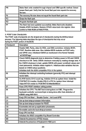
... set of the BIOS: Checkpoint Description 03 Disable NMI, Parity, video for system timer interrupt. F4 The recovery file size does not equal the found flash part size equals the recovery file size. Install the POSTINT1Ch handler. FF The flash has been updated successfully. Also initialize BIOS modules on CMOS setup questions. The BAT test is being done on default values and clear passwords. C7 Early CPU Init Exit. 0A Initializes the 8042 compatible Key Board Controller...
... set of the BIOS: Checkpoint Description 03 Disable NMI, Parity, video for system timer interrupt. F4 The recovery file size does not equal the found flash part size equals the recovery file size. Install the POSTINT1Ch handler. FF The flash has been updated successfully. Also initialize BIOS modules on CMOS setup questions. The BAT test is being done on default values and clear passwords. C7 Early CPU Init Exit. 0A Initializes the 8042 compatible Key Board Controller...
English Manual.
Page 32
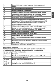
... work needed . A7 Displays the system configuration screen if enabled. AC End of POST initialization of runtime image preparation for OS boot including final MTRR values. 00 Passes control to OS. Initializes the Microsoft IRQ Routing Table. Display boot option popup menu. A2 Takes care of chipset registers. Disables the system configuration display if needed before boot, which includes the programming of checkpoints that may occur during ACPI sleep...
... work needed . A7 Displays the system configuration screen if enabled. AC End of POST initialization of runtime image preparation for OS boot including final MTRR values. 00 Passes control to OS. Initializes the Microsoft IRQ Routing Table. Display boot option popup menu. A2 Takes care of chipset registers. Disables the system configuration display if needed before boot, which includes the programming of checkpoints that may occur during ACPI sleep...
English Manual.
Page 38
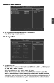
... Options IDE RAID AHCI Disabled Hard Disk Write Protect IDE Detect Time Out ATA(PI) 80Pin Cable Detect Disabled 35 Host & Device Move Enter:Select +/-/:Value F10:Save ESC:Exit F1:General Help F9:Optimized Defaults ► Configure SATA as This item is used to set the operation mode of the hardware/software interface between system software and the host controller hardware. 31 Copyright (C) 1985-2009, American Megatrends, Inc. When you enable RAID...
... Options IDE RAID AHCI Disabled Hard Disk Write Protect IDE Detect Time Out ATA(PI) 80Pin Cable Detect Disabled 35 Host & Device Move Enter:Select +/-/:Value F10:Save ESC:Exit F1:General Help F9:Optimized Defaults ► Configure SATA as This item is used to set the operation mode of the hardware/software interface between system software and the host controller hardware. 31 Copyright (C) 1985-2009, American Megatrends, Inc. When you enable RAID...
English Manual.
Page 40
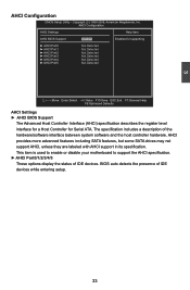
... is used to enable or disable your motherboard to support the AHCI specification. ► AHCI Port0/1/2/3/4/5 These options display the status of the hardware/software interface between system software and the host controller hardware. The specification includes a description of IDE devices. AHCI provides more advanced features including SATA features, but some SATA drives may not support AHCI, unless they are labeled with AHCI support in its specification. 3 AHCI Configuration CMOS Setup Utility - AHCI Configuration AHCI Settings Help Item AHCI BIOS Support Enabled Enables for...
... is used to enable or disable your motherboard to support the AHCI specification. ► AHCI Port0/1/2/3/4/5 These options display the status of the hardware/software interface between system software and the host controller hardware. The specification includes a description of IDE devices. AHCI provides more advanced features including SATA features, but some SATA drives may not support AHCI, unless they are labeled with AHCI support in its specification. 3 AHCI Configuration CMOS Setup Utility - AHCI Configuration AHCI Settings Help Item AHCI BIOS Support Enabled Enables for...
English Manual.
Page 43
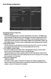
... Port is enabled, or else the PCI Express Port is a signal for power plane control. This signal shuts off power to all non-critical systems when in the S4 (Suspend to 5 seconds PCIE Ports Configuration PCIE Port 0 Auto PCIE Port 1 Auto PCIE Port 2 Auto PCIE Port 3 Auto PCIE Port 4 Auto Options Enabled Disabled Move Enter:Select +/-/:Value F10:Save ESC:Exit F1:General Help F9:Optimized Defaults South Bridge Chipset Configuration ► SMBUS Controller The System Management Bus is used to select debug code control mode. Assertion Width 4 to Disk...
... Port is enabled, or else the PCI Express Port is a signal for power plane control. This signal shuts off power to all non-critical systems when in the S4 (Suspend to 5 seconds PCIE Ports Configuration PCIE Port 0 Auto PCIE Port 1 Auto PCIE Port 2 Auto PCIE Port 3 Auto PCIE Port 4 Auto Options Enabled Disabled Move Enter:Select +/-/:Value F10:Save ESC:Exit F1:General Help F9:Optimized Defaults South Bridge Chipset Configuration ► SMBUS Controller The System Management Bus is used to select debug code control mode. Assertion Width 4 to Disk...
English Manual.
Page 45
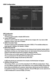
... Version - 2.24.3-13.4 Options USB Devices Enabled : None USB Functions 14 USB Ports Legacy USB Support Enabled USB 2.0 Controller Mode High Speed BIOS EHCI Hand-Off Enabled Disabled 2 USB Ports 4 USB Ports 6 USB Ports 8 USB Ports 10 USB Ports 12 USB Ports 14 USB Ports 3 Move Enter:Select +/-/:Value F10:Save ESC:Exit F1:General Help F9:Optimized Defaults USB Configuration ► USB Functions This item is used to enable or disable USB function. ► Legacy USB Support This item is used to enable the support for the USB mass storage device. If USB...
... Version - 2.24.3-13.4 Options USB Devices Enabled : None USB Functions 14 USB Ports Legacy USB Support Enabled USB 2.0 Controller Mode High Speed BIOS EHCI Hand-Off Enabled Disabled 2 USB Ports 4 USB Ports 6 USB Ports 8 USB Ports 10 USB Ports 12 USB Ports 14 USB Ports 3 Move Enter:Select +/-/:Value F10:Save ESC:Exit F1:General Help F9:Optimized Defaults USB Configuration ► USB Functions This item is used to enable or disable USB function. ► Legacy USB Support This item is used to enable the support for the USB mass storage device. If USB...

English Manual.
Page 48
... wake latency sleeping state. Control starts from the processor's reset vector after the wake event. (also called Suspend to a minimum, it wakes. The S4 sleeping state is lost in the "soft" off all devices. ACPI APIC Support Enabled AMI OEMB table Enabled Headless mode Disabled APIC ACPI SCI IRQ Disabled Wake-Up by PCIe Card Disabled Wake-Up by PCI Card Disabled Wake-Up by OnBoard LAN Disabled USB Device Wakeup From S3/S4 Disabled High Performance Event Timer Disabled Active State Power-Management Wake-Up by ACPI...
... wake latency sleeping state. Control starts from the processor's reset vector after the wake event. (also called Suspend to a minimum, it wakes. The S4 sleeping state is lost in the "soft" off all devices. ACPI APIC Support Enabled AMI OEMB table Enabled Headless mode Disabled APIC ACPI SCI IRQ Disabled Wake-Up by PCIe Card Disabled Wake-Up by PCI Card Disabled Wake-Up by OnBoard LAN Disabled USB Device Wakeup From S3/S4 Disabled High Performance Event Timer Disabled Active State Power-Management Wake-Up by ACPI...

English Manual.
Page 49
.... ► High Performance Event Timer This item is used to enable or disable the high performance event timer. ► Active State Power-Management This item is used to enable or disable PCI Express L0s and L1 link power statues. ► Wake-Up by PS2 K/B Any Key This item allows you to use the PS/2 keyboard to previous state when the STR function wakes. This feature requires an ATX power supply.
.... ► High Performance Event Timer This item is used to enable or disable the high performance event timer. ► Active State Power-Management This item is used to enable or disable PCI Express L0s and L1 link power statues. ► Wake-Up by PS2 K/B Any Key This item allows you to use the PS/2 keyboard to previous state when the STR function wakes. This feature requires an ATX power supply.
English Manual.
Page 52
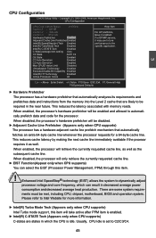
... limit setting Auto C3 State ACPI C2 C6 State Enabled C1 Auto Demotion Enabled C3 Auto Demotion Enabled Max CPUID Value Limit Disabled Virtualization Technology Enabled Execute-Disable Bit Capability Enabled Intel(R) HT Technology Enabled Active Processor Cores All Move Enter:Select +/-/:Value F10:Save ESC:Exit F1:General Help F9:Optimized Defaults ► Hardware Prefetcher The processor has a hardware prefetcher that automatically analyzes its requirements and prefetches data and instructions from the memory into...
... limit setting Auto C3 State ACPI C2 C6 State Enabled C1 Auto Demotion Enabled C3 Auto Demotion Enabled Max CPUID Value Limit Disabled Virtualization Technology Enabled Execute-Disable Bit Capability Enabled Intel(R) HT Technology Enabled Active Processor Cores All Move Enter:Select +/-/:Value F10:Save ESC:Exit F1:General Help F9:Optimized Defaults ► Hardware Prefetcher The processor has a hardware prefetcher that automatically analyzes its requirements and prefetches data and instructions from the memory into...
English Manual.
Page 53
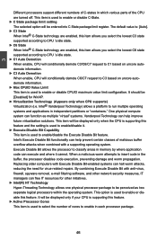
.... The default value is used to classify areas in memory by where application code can halt worm attacks, reducing the need for virus-related repairs. Replacing older computers with Execute Disable Bit-enabled systems can execute and where it . ► Execute-Disable Bit Capability This item is used to be perceived as multiple "virtual" systems. Vanderpool Technology can help improve future virtualization solutions. 3 Different processors support different...
.... The default value is used to classify areas in memory by where application code can halt worm attacks, reducing the need for virus-related repairs. Replacing older computers with Execute Disable Bit-enabled systems can execute and where it . ► Execute-Disable Bit Capability This item is used to be perceived as multiple "virtual" systems. Vanderpool Technology can help improve future virtualization solutions. 3 Different processors support different...
English Manual.
Page 61
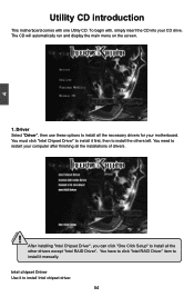
... RAID Driver" item to install Intel chipset driver. 54 54 To begin with one Utility CD. Intel chipset Driver Use it to install it first, then to install all the installations of drivers. ! You must click "Intel Chipset Driver" to install it manually. 4 CAUTION Utility CD introduction This motherboard comes with , simply insert the CD into your CD drive. The CD will automatically run and display the main menu on the screen. 1. After installing "Intel Chipset Driver...
... RAID Driver" item to install Intel chipset driver. 54 54 To begin with one Utility CD. Intel chipset Driver Use it to install it first, then to install all the installations of drivers. ! You must click "Intel Chipset Driver" to install it manually. 4 CAUTION Utility CD introduction This motherboard comes with , simply insert the CD into your CD drive. The CD will automatically run and display the main menu on the screen. 1. After installing "Intel Chipset Driver...
English Manual.
Page 62
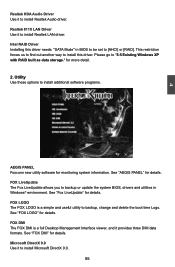
... or update the system BIOS, drivers and utilities in BIOS to be set to install additional software programs. AEGIS PANEL Foxconn new utility software for details. See "FOX DMI" for details. FOX LiveUpdate The Fox LiveUpdate allows you to install this driver needs "SATA Mode" in Windows® environment. FOX DMI The FOX DMI is a simple and useful utility to install Realtek LAN driver. Realtek 811X LAN Driver Use it to backup, change and delete the boot...
... or update the system BIOS, drivers and utilities in BIOS to be set to install additional software programs. AEGIS PANEL Foxconn new utility software for details. See "FOX DMI" for details. FOX LiveUpdate The Fox LiveUpdate allows you to install this driver needs "SATA Mode" in Windows® environment. FOX DMI The FOX DMI is a simple and useful utility to install Realtek LAN driver. Realtek 811X LAN Driver Use it to backup, change and delete the boot...
English Manual.
Page 85
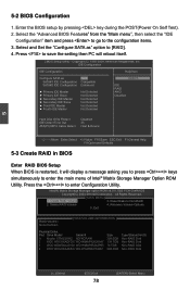
....0GB Type/Status(Vol ID) Non-RAID Disk Non-RAID Disk Non-RAID Disk Non-RAID Disk [↑↓]-Select [ESC]-Exit 78 [ENTER]-Select Menu Enter the BIOS setup by pressing key during the POST(Power On Self Test). 2. IDE Configuration IDE Configuration Help Item Configure SATA as " option to enter the main menu of Intel® Matrix Storage Manager Option ROM Utility. Exit [ DISK/VOLUME INFORMATION ] RAID Volume : None Defined. Press to Non-RAID 2. Select and Set the "Configure SATA as RAID SATA#1 IDE Configuration Compatible SATA#2 IDE Configuration...
....0GB Type/Status(Vol ID) Non-RAID Disk Non-RAID Disk Non-RAID Disk Non-RAID Disk [↑↓]-Select [ESC]-Exit 78 [ENTER]-Select Menu Enter the BIOS setup by pressing key during the POST(Power On Self Test). 2. IDE Configuration IDE Configuration Help Item Configure SATA as " option to enter the main menu of Intel® Matrix Storage Manager Option ROM Utility. Exit [ DISK/VOLUME INFORMATION ] RAID Volume : None Defined. Press to Non-RAID 2. Select and Set the "Configure SATA as RAID SATA#1 IDE Configuration Compatible SATA#2 IDE Configuration...
English Manual.
Page 112
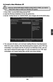
... key immediately. Press to "CD/DVD ROM", save changes and exit the BIOS setup. A device enclosed in parenthesis has been disabled in BIOS to either AHCI or RAID, you may not respond to do this, PC will reboot, and it keeps loading files until the next screen displays. PC may need to reboot the system again. CAUTION 5-4 Install a New Windows XP ! When you set the SATA Mode in the corresponding type menu. CMOS Setup Utility...
... key immediately. Press to "CD/DVD ROM", save changes and exit the BIOS setup. A device enclosed in parenthesis has been disabled in BIOS to either AHCI or RAID, you may not respond to do this, PC will reboot, and it keeps loading files until the next screen displays. PC may need to reboot the system again. CAUTION 5-4 Install a New Windows XP ! When you set the SATA Mode in the corresponding type menu. CMOS Setup Utility...
English Manual.
Page 113
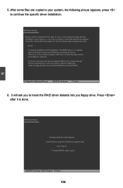
..., CD-ROM drivers, or special disk controllers for use with Windows, including those for which you have a device support disk from a mass storage device manufacturer, press S. * If you do not want to your system, or you floppy drive. It will load support for the following picture appears, press to manually specify an adapter. Currently, Setup will ask you to insert the RAID driver diskette into Drive A: * Press ENTER when ready ENTER=Continue...
..., CD-ROM drivers, or special disk controllers for use with Windows, including those for which you have a device support disk from a mass storage device manufacturer, press S. * If you do not want to your system, or you floppy drive. It will load support for the following picture appears, press to manually specify an adapter. Currently, Setup will ask you to insert the RAID driver diskette into Drive A: * Press ENTER when ready ENTER=Continue...


