User manual
Page 9
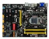
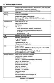
Support for H67A-S) Support USB 2.0 protocol up to 32GB of system memory Dual channel DDR3 1333/1066 MHz architecture 1 x PCI Express x16 slot 2 x PCI Express x1 slots 3 x PCI ... 0, 1, 5, 10 Realtek 8111E G��i�g�a�b�i�t �L�A�N���c�h�ip� Realtek ALC888S audio chip: - High Definition Audio - 2/4/5.1/7.1-channel - 1 1-1 Product Specifications CPU Chipset Memory Expansion Slots Storage LAN Audio USB Internal Connectors Support LGA1155 socket Intel® CPU, Max processor power up...
Support for H67A-S) Support USB 2.0 protocol up to 32GB of system memory Dual channel DDR3 1333/1066 MHz architecture 1 x PCI Express x16 slot 2 x PCI Express x1 slots 3 x PCI ... 0, 1, 5, 10 Realtek 8111E G��i�g�a�b�i�t �L�A�N���c�h�ip� Realtek ALC888S audio chip: - High Definition Audio - 2/4/5.1/7.1-channel - 1 1-1 Product Specifications CPU Chipset Memory Expansion Slots Storage LAN Audio USB Internal Connectors Support LGA1155 socket Intel® CPU, Max processor power up...
User manual
Page 13
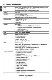
...an USB keyboard/mouse, USB printer, USB flash drive and etc. 8. 1 4. External SATA Port To connect external SATA device(s) to this port for H67A-S) You need to the table below : Port Blue Green Pink Orange Black Grey 2-channel Line In Line Out Microphone In - 4-channel Line In Front ...Speaker Out Microphone In - Audio Ports For the definition of each audio port, please refer to install the USB 3.0 driver in the Driver CD before using it. Rear Speaker Out - 5.1-channel Line In...
...an USB keyboard/mouse, USB printer, USB flash drive and etc. 8. 1 4. External SATA Port To connect external SATA device(s) to this port for H67A-S) You need to the table below : Port Blue Green Pink Orange Black Grey 2-channel Line In Line Out Microphone In - 4-channel Line In Front ...Speaker Out Microphone In - Audio Ports For the definition of each audio port, please refer to install the USB 3.0 driver in the Driver CD before using it. Rear Speaker Out - 5.1-channel Line In...
User manual
Page 21
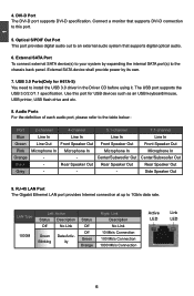
...the 8-pin ATX 12V power supply to PWR2 and provides power to the CPU. +12V 51 GND 84 PWR2 Pin # 1 2 3 4 Definition GND GND GND GND Pin # 5 6 7 8 Definition +12V +12V +12V +12V 14 14 2 CAUTION 2-4 Install other Internal Connectors Power Connectors This motherboard uses an ATX power supply. Make sure... that the power supply cable and pins are using a 20-pin power supply, you using a 24-pin power supply. Pin # Definition Pin # Definition 1 3.3V 13 3.3V 2 3.3V 14 -12V 3 GND 15 GND 4 +5V 16 PS_ON(Soft On/Off) 5 GND 17 GND 6 +5V 18 ...
...the 8-pin ATX 12V power supply to PWR2 and provides power to the CPU. +12V 51 GND 84 PWR2 Pin # 1 2 3 4 Definition GND GND GND GND Pin # 5 6 7 8 Definition +12V +12V +12V +12V 14 14 2 CAUTION 2-4 Install other Internal Connectors Power Connectors This motherboard uses an ATX power supply. Make sure... that the power supply cable and pins are using a 20-pin power supply, you using a 24-pin power supply. Pin # Definition Pin # Definition 1 3.3V 13 3.3V 2 3.3V 14 -12V 3 GND 15 GND 4 +5V 16 PS_ON(Soft On/Off) 5 GND 17 GND 6 +5V 18 ...
User manual
Page 25
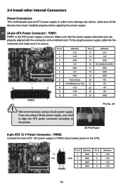
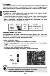
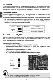
... pins 2-3 closed Clear CMOS Jumper: CLR_CMOS The motherboard uses CMOS RAM to modify them. This section explains how to clear CMOS data are : 1. Jumper 1 Diagram 1 1 Definition 1-2 2-3 Description Set Pin 1 and Pin 2 closed Set Pin 2 and Pin 3 closed . 4. WARNING! 1 Clear 2 3 Normal 1 (Default) 2 3 CLR_CMOS ■ ��D�i�s�c�o�n�...
... pins 2-3 closed Clear CMOS Jumper: CLR_CMOS The motherboard uses CMOS RAM to modify them. This section explains how to clear CMOS data are : 1. Jumper 1 Diagram 1 1 Definition 1-2 2-3 Description Set Pin 1 and Pin 2 closed Set Pin 2 and Pin 3 closed . 4. WARNING! 1 Clear 2 3 Normal 1 (Default) 2 3 CLR_CMOS ■ ��D�i�s�c�o�n�...
User manual
Page 9
... to 14 x USB 2.0 ports (6 rear panel ports, 4 onboard USB headers supporting 8 extra ports) Support up to 2 x USB 3.0 ports (Only for S/PDIF Out - High Definition Audio - 2/4/5.1/7.1-channel - Support for H67A-S) Support USB 2.0 protocol up to 480Mb/s 1 x 24-pin ATX main power connector 1 x 8-pin ATX 12V power connector 5 x SATA connectors 4 x USB 2.0 connectors (supporting 8 x USB...
... to 14 x USB 2.0 ports (6 rear panel ports, 4 onboard USB headers supporting 8 extra ports) Support up to 2 x USB 3.0 ports (Only for S/PDIF Out - High Definition Audio - 2/4/5.1/7.1-channel - Support for H67A-S) Support USB 2.0 protocol up to 480Mb/s 1 x 24-pin ATX main power connector 1 x 8-pin ATX 12V power connector 5 x SATA connectors 4 x USB 2.0 connectors (supporting 8 x USB...

User manual
Page 13
Audio Ports For the definition of each audio port, please refer to 1Gb/s data rate. LAN Type 1000M Left: Active Status Description Off No Link Green Data Activ- External SATA ... using it. Optical S/PDIF Out Port This port provides digital audio out to an external audio system that supports DVI-D connection to this port for H67A-S) You need to the chassis back panel. 1 4. Connect a monitor that supports digital optical audio. 6. The USB port supports the USB 3.0/2.0/1.1 specification. Use this port...
Audio Ports For the definition of each audio port, please refer to 1Gb/s data rate. LAN Type 1000M Left: Active Status Description Off No Link Green Data Activ- External SATA ... using it. Optical S/PDIF Out Port This port provides digital audio out to an external audio system that supports DVI-D connection to this port for H67A-S) You need to the chassis back panel. 1 4. Connect a monitor that supports digital optical audio. 6. The USB port supports the USB 3.0/2.0/1.1 specification. Use this port...

User manual
Page 21
... This motherboard uses an ATX power supply. In order not to the CPU. +12V 51 GND 84 PWR2 Pin # 1 2 3 4 Definition GND GND GND GND Pin # 5 6 7 8 Definition +12V +12V +12V +12V 14 14 Pin # Definition Pin # Definition 1 3.3V 13 3.3V 2 3.3V 14 -12V 3 GND 15 GND 4 +5V 16 PS_ON(Soft On/Off) 5 GND 17 GND...
... This motherboard uses an ATX power supply. In order not to the CPU. +12V 51 GND 84 PWR2 Pin # 1 2 3 4 Definition GND GND GND GND Pin # 5 6 7 8 Definition +12V +12V +12V +12V 14 14 Pin # Definition Pin # Definition 1 3.3V 13 3.3V 2 3.3V 14 -12V 3 GND 15 GND 4 +5V 16 PS_ON(Soft On/Off) 5 GND 17 GND...
User manual
Page 25
... (Electrical Static Discharge) problem. The steps to modifying any jumper on . 18 18 Plug in next chapter. "Closed" means placing a jumper cap on . 5. Jumper 1 Diagram 1 1 Definition 1-2 2-3 Description Set Pin 1 and Pin 2 closed Set Pin 2 and Pin 3 closed . 4. Description of the jumper settings. WARNING! 1 Clear 2 3 Normal 1 (Default) 2 3 CLR_CMOS ■ Disconnect the power...
... (Electrical Static Discharge) problem. The steps to modifying any jumper on . 18 18 Plug in next chapter. "Closed" means placing a jumper cap on . 5. Jumper 1 Diagram 1 1 Definition 1-2 2-3 Description Set Pin 1 and Pin 2 closed Set Pin 2 and Pin 3 closed . 4. Description of the jumper settings. WARNING! 1 Clear 2 3 Normal 1 (Default) 2 3 CLR_CMOS ■ Disconnect the power...