User manual
Page 6
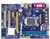
... Channel Memory Configuration 11 Installing a Memory 11 2-3 Install an Expansion Card 13 2-4 Install other Internal Connectors 14 2-5 Jumper 17 Chapter 3 BIOS Setup Enter BIOS Setup 20 Main...21 F-Center...23 Smart BIOS 23 Fox Intelligent Stepping 24 CPU Configuration 25 Performance Tuning 26 Advanced...28 North Bridge 28 ME Subsystem 29 Onboard Device...
... Channel Memory Configuration 11 Installing a Memory 11 2-3 Install an Expansion Card 13 2-4 Install other Internal Connectors 14 2-5 Jumper 17 Chapter 3 BIOS Setup Enter BIOS Setup 20 Main...21 F-Center...23 Smart BIOS 23 Fox Intelligent Stepping 24 CPU Configuration 25 Performance Tuning 26 Advanced...28 North Bridge 28 ME Subsystem 29 Onboard Device...
User manual
Page 15
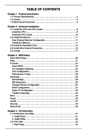
... for the peripherals. The CPU cannot be set the frequency beyond hardware specifications since it does not meet the standard requirements for HT Technology ■ A BIOS that supports HT Technology and has it enabled Install the CPU Locate the alignment keys on the motherboard CPU socket and the notches on the...
... for the peripherals. The CPU cannot be set the frequency beyond hardware specifications since it does not meet the standard requirements for HT Technology ■ A BIOS that supports HT Technology and has it enabled Install the CPU Locate the alignment keys on the motherboard CPU socket and the notches on the...
User manual
Page 20
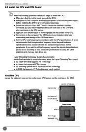
...: • Installing a Graphics Card: Gently insert the graphics card into the slot. 4. Secure the card's metal bracket to make any required BIOS changes for your card. If necessary, go to BIOS Setup to the chassis back panel with the slot, and press down on your computer. After installing all expansion cards, replace...
...: • Installing a Graphics Card: Gently insert the graphics card into the slot. 4. Secure the card's metal bracket to make any required BIOS changes for your card. If necessary, go to BIOS Setup to the chassis back panel with the slot, and press down on your computer. After installing all expansion cards, replace...
User manual
Page 23
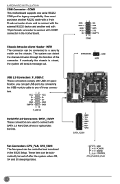
... automatically turned off after the system enters S3, S4 and S5 sleeping states. fication, you can be connected to connect with COM1 connector in the BIOS Setup. The system can be controlled and monitored in the motherboard. tors. DCD SOUT GND RTS RI 12 9 10 SIN DTR DSR CTS EMPTY COM2...
... automatically turned off after the system enters S3, S4 and S5 sleeping states. fication, you can be connected to connect with COM1 connector in the BIOS Setup. The system can be controlled and monitored in the motherboard. tors. DCD SOUT GND RTS RI 12 9 10 SIN DTR DSR CTS EMPTY COM2...
User manual
Page 24
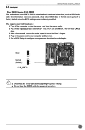
...as a screwdriver) onto pins 1-2 to configure new system as described in the power cord to clear CMOS data are : 1. Go to BIOS Setup to short them. Clear CMOS data is turned on . 5. 2-5 Jumper HARDWARE INSTALLATION Clear CMOS Header: CLR_CMOS The motherboard uses CMOS ...RAM to factory default when the BIOS settings were mistakenly modified. This will clear CMOS data. 3. The steps to your computer and turn it on . Plug in next chapter. 1 ...
...as a screwdriver) onto pins 1-2 to configure new system as described in the power cord to clear CMOS data are : 1. Go to BIOS Setup to short them. Clear CMOS data is turned on . 5. 2-5 Jumper HARDWARE INSTALLATION Clear CMOS Header: CLR_CMOS The motherboard uses CMOS ...RAM to factory default when the BIOS settings were mistakenly modified. This will clear CMOS data. 3. The steps to your computer and turn it on . Plug in next chapter. 1 ...
User manual
Page 25
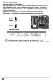
... 2 (Default) 3 1 Disable 2 3 PCH_ME_ENABLE Definition 1-2(default) 2-3 Description Set Pin 1 and Pin 2 closed Set Pin 2 and Pin 3 closed Function Enable ME function Disable ME function Before flashing BIOS ROM, you can enable the Intel® Management Engine function. CAUTION 18
... 2 (Default) 3 1 Disable 2 3 PCH_ME_ENABLE Definition 1-2(default) 2-3 Description Set Pin 1 and Pin 2 closed Set Pin 2 and Pin 3 closed Function Enable ME function Disable ME function Before flashing BIOS ROM, you can enable the Intel® Management Engine function. CAUTION 18
User manual
Page 26
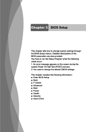
An error message appears on the screen during the system Power On Self Test (POST) process. 2. Chapter 3 BIOS Setup This chapter tells how to run the Setup Program when the following information : ■ Enter BIOS Setup ■ Main ■ F-Center ■ Advanced ■ Boot ■ Power ■ Health ■ Security ■ Save & Exit You have to change the default CMOS settings. This chapter includes the following cases occur: 1. You want to change system settings through the BIOS Setup menus. Detailed descriptions of the BIOS parameters are also provided.
An error message appears on the screen during the system Power On Self Test (POST) process. 2. Chapter 3 BIOS Setup This chapter tells how to run the Setup Program when the following information : ■ Enter BIOS Setup ■ Main ■ F-Center ■ Advanced ■ Boot ■ Power ■ Health ■ Security ■ Save & Exit You have to change the default CMOS settings. This chapter includes the following cases occur: 1. You want to change system settings through the BIOS Setup menus. Detailed descriptions of the BIOS parameters are also provided.
User manual
Page 27
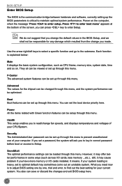
... one by one, trial and error, to find out the best setting for any damage which resulted from the change the default values in the BIOS Setup, and we shall not be set a password, the system will ask you have more memory or I /O cards, less memory ...etc.), still, it may...be viewed or set up through this menu. If you made. Save&Exit The optimal performance settings can be setup through this menu. BIOS SETUP Enter BIOS Setup The BIOS is the communication bridge between hardware and software, correctly setting up through this menu. Power on . You also can press key to ...
... one by one, trial and error, to find out the best setting for any damage which resulted from the change the default values in the BIOS Setup, and we shall not be set a password, the system will ask you have more memory or I /O cards, less memory ...etc.), still, it may...be viewed or set up through this menu. If you made. Save&Exit The optimal performance settings can be setup through this menu. BIOS SETUP Enter BIOS Setup The BIOS is the communication bridge between hardware and software, correctly setting up through this menu. Power on . You also can press key to ...
User manual
Page 28
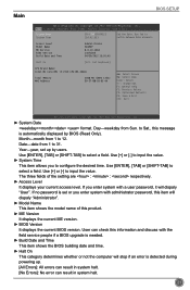
...Security Save & Exit System Date System Time [Fri 04/20/2012] Set the Date. Access Level Model Name ME Version BIOS Version Build Date and Time Administrator H61MXP 8.0.10.1464 C36F1D05 04/20/2012 15:01:45 Halt On [All, but keyboard] CPU Brand Name: Intel(R) Core(...4A Enter: Select +/-: Change Opt. If you to Sat., this product. ► ME Version It displays the current ME version. ► BIOS Version It displays the current BIOS version. Use Tab to select a field. Copyright (C) 2012 American Megatrends, Inc. ► System Date format. Use [+] or [-] to 31....
...Security Save & Exit System Date System Time [Fri 04/20/2012] Set the Date. Access Level Model Name ME Version BIOS Version Build Date and Time Administrator H61MXP 8.0.10.1464 C36F1D05 04/20/2012 15:01:45 Halt On [All, but keyboard] CPU Brand Name: Intel(R) Core(...4A Enter: Select +/-: Change Opt. If you to Sat., this product. ► ME Version It displays the current ME version. ► BIOS Version It displays the current BIOS version. Use Tab to select a field. Copyright (C) 2012 American Megatrends, Inc. ► System Date format. Use [+] or [-] to 31....

User manual
Page 29
The size is depending on . ► MAC Address This item displays the onboard LAN MAC address. 22 BIOS SETUP [All, but keyboard]: All errors but keyboard can result in your system before powering on how many memory modules are installed in system halt. ► CPU Brand Name It displays the current CPU name. ► Total Memory This item displays the total memory size.
The size is depending on . ► MAC Address This item displays the onboard LAN MAC address. 22 BIOS SETUP [All, but keyboard]: All errors but keyboard can result in your system before powering on how many memory modules are installed in system halt. ► CPU Brand Name It displays the current CPU name. ► Total Memory This item displays the total memory size.
User manual
Page 30
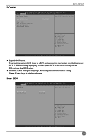
... Setup Utility - Main AFd-vCaenctedr Advanced Boot Power Health Security Save & Exit Fox Control Center Super BIOS Protection Settings Super BIOS Protect [Disabled] ▶ Smart BIOS ▶ Fox Intelligent Stepping ▶ CPU Configuration ▶ Performance Tuning → ←: Select ... (C) 2012 American Megatrends, Inc. C opyright (C) 2011 American Megatrends, Inc. Copyright (C) 2011 American Megatrends, Inc. 23 F-Center Smart BIOS Smart Power LED Settings Smart Power LED Smart Boot Menu [Disabled] [Enabled] → ←: Select Screen ↑ ↓: Select...
... Setup Utility - Main AFd-vCaenctedr Advanced Boot Power Health Security Save & Exit Fox Control Center Super BIOS Protection Settings Super BIOS Protect [Disabled] ▶ Smart BIOS ▶ Fox Intelligent Stepping ▶ CPU Configuration ▶ Performance Tuning → ←: Select ... (C) 2012 American Megatrends, Inc. C opyright (C) 2011 American Megatrends, Inc. Copyright (C) 2011 American Megatrends, Inc. 23 F-Center Smart BIOS Smart Power LED Settings Smart Power LED Smart Boot Menu [Disabled] [Enabled] → ←: Select Screen ↑ ↓: Select...
User manual
Page 31
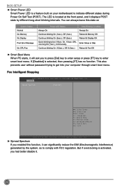
... is located at the front panel, and it displays POST state by the system, so to indicate different states during Power On Self Test (POST). BIOS SETUP ► Smart Power LED Smart Power LED is selected, then pressing [F7] has no function. Off), one long On (1sec.), continuously. F-Center Spread Spectrum...
... is located at the front panel, and it displays POST state by the system, so to indicate different states during Power On Self Test (POST). BIOS SETUP ► Smart Power LED Smart Power LED is selected, then pressing [F7] has no function. Off), one long On (1sec.), continuously. F-Center Spread Spectrum...
User manual
Page 32
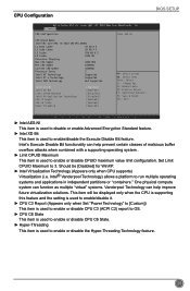
...; ←: Select Screen ↑ ↓: Select Item Enter: Select +/-: Change Opt. F1: General Help F2: Previous Values F3: Optimized Defaults F4: Save & Reset ESC: Exit BIOS SETUP Version 2.14.1219. Should be displayed only when the CPU is supporting this feature and the setting is used to enable/disable it. ►...
...; ←: Select Screen ↑ ↓: Select Item Enter: Select +/-: Change Opt. F1: General Help F2: Previous Values F3: Optimized Defaults F4: Save & Reset ESC: Exit BIOS SETUP Version 2.14.1219. Should be displayed only when the CPU is supporting this feature and the setting is used to enable/disable it. ►...
User manual
Page 33
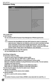
There are some system requirements must be met, including CPU, chipset, motherboard, BIOS and operation system. Configuration database of using performance memory profile. [Manual]- The following items appear only when the option is set to...; Memory Clock Multiplier This item is used to set the memory clock multiplier. ► Memory Multiplier This item is used to select Performance memory profile. BIOS SETUP Performance Tuning Aptio Setup Utility - Copyright (C) 2012 American Megatrends, Inc. Options: [Automatic], [Manual], [XMP Profile 1], [XMP Profile 2]. [Automatic]- ...
There are some system requirements must be met, including CPU, chipset, motherboard, BIOS and operation system. Configuration database of using performance memory profile. [Manual]- The following items appear only when the option is set to...; Memory Clock Multiplier This item is used to set the memory clock multiplier. ► Memory Multiplier This item is used to select Performance memory profile. BIOS SETUP Performance Tuning Aptio Setup Utility - Copyright (C) 2012 American Megatrends, Inc. Options: [Automatic], [Manual], [XMP Profile 1], [XMP Profile 2]. [Automatic]- ...
User manual
Page 34
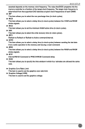
.... ► Graphics Voltage(1/256) This item is determined from the supported CAS latencies at given clock frequencies of the target clock frequency. The value that BIOS programs into the memory controller is a function of each DIMM. ► tRP This item allows you to select the row precharge time (in clock cycles... window in which four activates are allowed the same rank. ► Graphics Core Ratio Limit This item is used to set the graphics voltage. 27 BIOS SETUP asserted depends on the memory clock frequency.
.... ► Graphics Voltage(1/256) This item is determined from the supported CAS latencies at given clock frequencies of the target clock frequency. The value that BIOS programs into the memory controller is a function of each DIMM. ► tRP This item allows you to select the row precharge time (in clock cycles... window in which four activates are allowed the same rank. ► Graphics Core Ratio Limit This item is used to set the graphics voltage. 27 BIOS SETUP asserted depends on the memory clock frequency.
User manual
Page 35
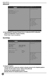
... Help F2: Previous Values F3: Optimized Defaults F4: Save & Reset ESC: Exit Version 2.14.1219. North Bridge Aptio Setup Utility - C opyright (C) 2012 American Megatrends, Inc. BIOS SETUP Advanced Aptio Setup Utility -
... Help F2: Previous Values F3: Optimized Defaults F4: Save & Reset ESC: Exit Version 2.14.1219. North Bridge Aptio Setup Utility - C opyright (C) 2012 American Megatrends, Inc. BIOS SETUP Advanced Aptio Setup Utility -
User manual
Page 36
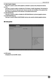
F1: General Help F2: Previous Values F3: Optimized Defaults F4: Save & Exit ESC: Exit Version 2.14.1219. BIOS SETUP ► Initial Graphic Adapter This item is used to select which graphics controller is used as the primary boot device. ► VT-d This item ...
F1: General Help F2: Previous Values F3: Optimized Defaults F4: Save & Exit ESC: Exit Version 2.14.1219. BIOS SETUP ► Initial Graphic Adapter This item is used to select which graphics controller is used as the primary boot device. ► VT-d This item ...
User manual
Page 37
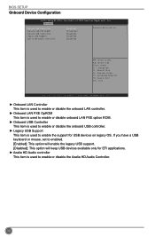
C opyright (C) 2012 American Megatrends, Inc. F1: General Help F2: Previous Values F3: Optimized Defaults F4: Save & Exit ESC: Exit Version 2.14.1219. BIOS SETUP Onboard Device Configuration Aptio Setup Utility - Copyright (C) 2012 American Megatrends, Inc. ► Onboard LAN Controller This item is used to enable or disable the ...
C opyright (C) 2012 American Megatrends, Inc. F1: General Help F2: Previous Values F3: Optimized Defaults F4: Save & Exit ESC: Exit Version 2.14.1219. BIOS SETUP Onboard Device Configuration Aptio Setup Utility - Copyright (C) 2012 American Megatrends, Inc. ► Onboard LAN Controller This item is used to enable or disable the ...
User manual
Page 38
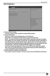
... advanced features including SATA features, but some SATA drives may not support AHCI, unless they are labeled with AHCI support in its submenu. SATA Configuration BIOS SETUP Aptio Setup Utility - Advanced SATA Configuration Onboard SATA Controller Onboard SATA Mode [Enabled] [Native IDE] SATA Ports Device Names if Present and Enabled. ▶...
... advanced features including SATA features, but some SATA drives may not support AHCI, unless they are labeled with AHCI support in its submenu. SATA Configuration BIOS SETUP Aptio Setup Utility - Advanced SATA Configuration Onboard SATA Controller Onboard SATA Mode [Enabled] [Native IDE] SATA Ports Device Names if Present and Enabled. ▶...
User manual
Page 39
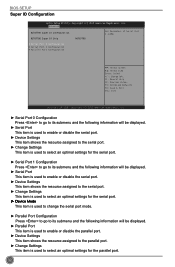
BIOS SETUP Super IO Configuration Aptio Setup Utility - F1: General Help F2: Previous Values F3: Optimized Defaults F4: Save & Exit ESC: Exit Version 2.14.1219. Copyright (C) ...
BIOS SETUP Super IO Configuration Aptio Setup Utility - F1: General Help F2: Previous Values F3: Optimized Defaults F4: Save & Exit ESC: Exit Version 2.14.1219. Copyright (C) ...


