English Manual.
Page 5
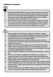
... the motherboard and CPU due to unplug the power supply cord may result in contact with the connectors on the motherboard. Failure to high temperature. Also, make sure their pinouts are uncertain about any metal leads or connectors. ■ If there is a PCI Express x16 graphics card installed in your system, we recommend using a 24-pin ATX power supply to get the best performance. ■ Before turning on the computer if the CPU fan...
... the motherboard and CPU due to unplug the power supply cord may result in contact with the connectors on the motherboard. Failure to high temperature. Also, make sure their pinouts are uncertain about any metal leads or connectors. ■ If there is a PCI Express x16 graphics card installed in your system, we recommend using a 24-pin ATX power supply to get the best performance. ■ Before turning on the computer if the CPU fan...
English Manual.
Page 9
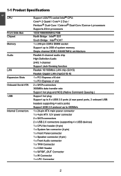
...slot 1 x PCI Express x1 slot Onboard Serial ATA 2 x SATA connectors 300MB/s data transfer rate Support hot plug and NCQ (Native Command Queuing ) USB Support hot plug Support up to 8 x USB 2.0 ports (4 rear panel ports, 2 onboard USB headers supporting 4 extra ports) Support USB 2.0 protocol up to 480Mb/s Internal Connectors 1 x 24-pin ATX main power connector 1 x 4-pin ATX 12V power connector 2 x SATA connectors 2 x USB 2.0 connectors (supporting 4 x USB devices) 1 x CPU fan header (4-pin) 1 x System fan connector (4-pin) 1 x Front Panel connector 1 x Speaker...
...slot 1 x PCI Express x1 slot Onboard Serial ATA 2 x SATA connectors 300MB/s data transfer rate Support hot plug and NCQ (Native Command Queuing ) USB Support hot plug Support up to 8 x USB 2.0 ports (4 rear panel ports, 2 onboard USB headers supporting 4 extra ports) Support USB 2.0 protocol up to 480Mb/s Internal Connectors 1 x 24-pin ATX main power connector 1 x 4-pin ATX 12V power connector 2 x SATA connectors 2 x USB 2.0 connectors (supporting 4 x USB devices) 1 x CPU fan header (4-pin) 1 x System fan connector (4-pin) 1 x Front Panel connector 1 x Speaker...
English Manual.
Page 10
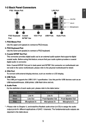
1 Back Panel 1 x PS/2 keyboard port Connectors 1 x PS/2 mouse port 1 x VGA port 1 x Coaxial S/PDIF Out Connector 4 x USB 2.0 ports 1 x RJ-45 LAN port 6-channel Audio ports Hardware Monitor System voltage detection CPU/System temperature detection CPU/System fan speed detection CPU/System overheating shutdown CPU/System fan speed control PCI Express x1 Support 250MB/s (500MB/s concurrent) bandwidth Low power consumption and power management features PCI Express x16 Support 4GB/s (8GB/s concurrent) bandwidth Low power consumption and power management ...
1 Back Panel 1 x PS/2 keyboard port Connectors 1 x PS/2 mouse port 1 x VGA port 1 x Coaxial S/PDIF Out Connector 4 x USB 2.0 ports 1 x RJ-45 LAN port 6-channel Audio ports Hardware Monitor System voltage detection CPU/System temperature detection CPU/System fan speed detection CPU/System overheating shutdown CPU/System fan speed control PCI Express x1 Support 250MB/s (500MB/s concurrent) bandwidth Low power consumption and power management features PCI Express x16 Support 4GB/s (8GB/s concurrent) bandwidth Low power consumption and power management ...
English Manual.
Page 12
.... 4. VGA Port To connect with external display devices, such as an USB keyboard/mouse, USB printer, USB flash drive and etc. 6. USB Ports The USB port supports the USB 2.0/1.1 specification. PS/2 Keyboard Port Use the lower port (purple) to connect a PS/2 mouse. 2. Audio Ports For the definition of 2/4/5.1 channels. The fundamental audio outputs are depicted in the same motherboard, please refer to assign the audio output ports for USB devices such as monitor or LCD display. 5. Use this feature, ensure that supports digital coaxial audio. Before using this port...
.... 4. VGA Port To connect with external display devices, such as an USB keyboard/mouse, USB printer, USB flash drive and etc. 6. USB Ports The USB port supports the USB 2.0/1.1 specification. PS/2 Keyboard Port Use the lower port (purple) to connect a PS/2 mouse. 2. Audio Ports For the definition of 2/4/5.1 channels. The fundamental audio outputs are depicted in the same motherboard, please refer to assign the audio output ports for USB devices such as monitor or LCD display. 5. Use this feature, ensure that supports digital coaxial audio. Before using this port...
English Manual.
Page 14
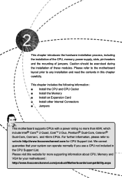
....foxconnchannel.com/product/Motherboards/compatibility.aspx This chapter introduces the hardware installation process, including the installation of the CPU, memory, power supply, slots, pin headers and the mounting of these modules. This chapter includes the following information : ■ Install the CPU and CPU Cooler ■ Install the Memory ■ Install an Expansion Card ■ Install other Internal Connectors ■ Jumpers This motherboard supports CPUs with a power rating no more supporting information about CPU, Memory and VGA for your system...
....foxconnchannel.com/product/Motherboards/compatibility.aspx This chapter introduces the hardware installation process, including the installation of the CPU, memory, power supply, slots, pin headers and the mounting of these modules. This chapter includes the following information : ■ Install the CPU and CPU Cooler ■ Install the Memory ■ Install an Expansion Card ■ Install other Internal Connectors ■ Jumpers This motherboard supports CPUs with a power rating no more supporting information about CPU, Memory and VGA for your system...
English Manual.
Page 19
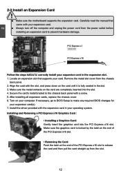
... panel. 2. Carefully read the manual that supports your operating system. Locate an expansion slot that came with the expansion card in the expansion slot. 1. 2 CAUTION 2-3 Install an Expansion Card ! ■ Make sure the motherboard supports the expansion card. After installing all expansion cards, replace the chassis cover. 6. Make sure the graphics card is fully seated in the slot. 3. Turn on the card are completely inserted into the PCI Express x16 slot. Installing and Removing a PCI Express x16 Graphics Card : • Installing a Graphics Card...
... panel. 2. Carefully read the manual that supports your operating system. Locate an expansion slot that came with the expansion card in the expansion slot. 1. 2 CAUTION 2-3 Install an Expansion Card ! ■ Make sure the motherboard supports the expansion card. After installing all expansion cards, replace the chassis cover. 6. Make sure the graphics card is fully seated in the slot. 3. Turn on the card are completely inserted into the PCI Express x16 slot. Installing and Removing a PCI Express x16 Graphics Card : • Installing a Graphics Card...

English Manual.
Page 22
Hard Disk LED Connector (HDD-LED) Connect to the power button on the front panel of the chassis. This 2-pin connector is directional with +/- sign. 1 + HDD-LED - 2 + PWR-LED - the system will restart when the switch is blinking; Power Switch Connector (PWR-SW) Connect to the chassis front panel IDE indicator LED. 2 Front Panel Connector : FP1 This motherboard includes one serial RS232 COM port for connecting the front panel switch and LED Indicators. This 2-pin connector is in the motherboard. 12 RLSD SIN SOUT DTR GND DSR RTS...
Hard Disk LED Connector (HDD-LED) Connect to the power button on the front panel of the chassis. This 2-pin connector is directional with +/- sign. 1 + HDD-LED - 2 + PWR-LED - the system will restart when the switch is blinking; Power Switch Connector (PWR-SW) Connect to the chassis front panel IDE indicator LED. 2 Front Panel Connector : FP1 This motherboard includes one serial RS232 COM port for connecting the front panel switch and LED Indicators. This 2-pin connector is in the motherboard. 12 RLSD SIN SOUT DTR GND DSR RTS...

English Manual.
Page 24
Description of the jumper settings. Return the setting to store the basic hardware information (such as BIOS data, date, time information, hardware password...etc.). Jumper 1 Diagram 1 1 Definition 1-2 2-3 Description Set Pin 1 and Pin 2 closed Set Pin 2 and Pin 3 closed Clear CMOS Jumper: CLR_CMOS The motherboard uses CMOS RAM to its original with pins 2-3 closed. 4. Remove jumper cap from the power outlet. 2. This section explains how to use the various functions of this motherboard by the bold silkscreen next...
Description of the jumper settings. Return the setting to store the basic hardware information (such as BIOS data, date, time information, hardware password...etc.). Jumper 1 Diagram 1 1 Definition 1-2 2-3 Description Set Pin 1 and Pin 2 closed Set Pin 2 and Pin 3 closed Clear CMOS Jumper: CLR_CMOS The motherboard uses CMOS RAM to its original with pins 2-3 closed. 4. Remove jumper cap from the power outlet. 2. This section explains how to use the various functions of this motherboard by the bold silkscreen next...

English Manual.
Page 27
... This setup enables you to read/change anything and exit the setup. ! It means, if your system loading is heavy, set to CMOS and exit. ► Exit Without Saving Do not change Fan speeds, and displays temperatures and voltages of your CPU/System. ► Load Optimized Defaults The optimal performance settings can be loaded through this menu. When we talk about and keys in some ways (such as less I/O cards, less memory...
... This setup enables you to read/change anything and exit the setup. ! It means, if your system loading is heavy, set to CMOS and exit. ► Exit Without Saving Do not change Fan speeds, and displays temperatures and voltages of your CPU/System. ► Load Optimized Defaults The optimal performance settings can be loaded through this menu. When we talk about and keys in some ways (such as less I/O cards, less memory...
English Manual.
Page 33
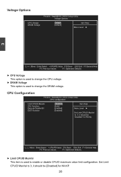
...Voltage Options CPU Voltage [Default] Item Help DRAM Voltage [Default] Menu Level ► 3 Move Enter:Select +/-/PU/PD:Value F10:Save ESC:Exit F1:General Help F5: Previous Values F7: Optimized Defaults ► CPU Voltage This option is used to change the DRAM voltage. Set Limit CPUID MaxVal to change the CPU voltage. ► DRAM Voltage This option is used to 3, it should be "Disabled" for WinXP. 26 CPU Configuration Phoenix - AwardBIOS CMOS Setup Utility CPU Configuration Limit CPUID MaxVal [Disabled] C1E Function [Auto] Execute Disable Bit...
...Voltage Options CPU Voltage [Default] Item Help DRAM Voltage [Default] Menu Level ► 3 Move Enter:Select +/-/PU/PD:Value F10:Save ESC:Exit F1:General Help F5: Previous Values F7: Optimized Defaults ► CPU Voltage This option is used to change the DRAM voltage. Set Limit CPUID MaxVal to change the CPU voltage. ► DRAM Voltage This option is used to 3, it should be "Disabled" for WinXP. 26 CPU Configuration Phoenix - AwardBIOS CMOS Setup Utility CPU Configuration Limit CPUID MaxVal [Disabled] C1E Function [Auto] Execute Disable Bit...

English Manual.
Page 34
... worm attempts to enable/disable the Execute Disable Bit feature. Enhanced Intel SpeedStep® technology (EIST) allows the system to dynamically adjust processor voltage and core frequency, which Intel CPU uses to classify areas in memory by where application code can result in the buffer, the processor disables code execution, preventing damage and worm propagation. There are some system requirements must be met, including CPU, chipset, motherboard, BIOS and operation...
... worm attempts to enable/disable the Execute Disable Bit feature. Enhanced Intel SpeedStep® technology (EIST) allows the system to dynamically adjust processor voltage and core frequency, which Intel CPU uses to classify areas in memory by where application code can result in the buffer, the processor disables code execution, preventing damage and worm propagation. There are some system requirements must be met, including CPU, chipset, motherboard, BIOS and operation...

English Manual.
Page 35
The CAS Latency is the number of DRAM timing by SPD device. Select [Manual], then you to set to [Manual]. ► CAS Latency Time This item controls the CAS latency. The Serial Presence Detect (SPD) device is used to enable/disable provision of clock cycles that the motherboard memory controller (chipset) can configure the DRAM timing manually. It contains important information about the module's speed, size, addressing mode and various other parameters, so...
The CAS Latency is the number of DRAM timing by SPD device. Select [Manual], then you to set to [Manual]. ► CAS Latency Time This item controls the CAS latency. The Serial Presence Detect (SPD) device is used to enable/disable provision of clock cycles that the motherboard memory controller (chipset) can configure the DRAM timing manually. It contains important information about the module's speed, size, addressing mode and various other parameters, so...

English Manual.
Page 38
... AwardBIOS CMOS Setup Utility Advanced Chipset Features System BIOS Cacheable [Enabled] Item Help Video BIOS Cacheable [Disabled] Menu Level ► ** VGA Setting ** PEG/Onchip VGA Control [Auto] On-Chip Frame Buffer Size 8MB DVMT Mode [DVMT] DVMT/FIXED Memory Size [256MB] Init Display First [PCI Slot] ** PCI Express Related items ** PCI Express x1 Port [Auto] PCI-E Compliancy Mode [v1.0a] Maximum Payload Size [128] 3 Move Enter:Select +/-/PU/PD:Value F10:Save ESC:Exit F1:General Help F5: Previous Values F7: Optimized Defaults...
... AwardBIOS CMOS Setup Utility Advanced Chipset Features System BIOS Cacheable [Enabled] Item Help Video BIOS Cacheable [Disabled] Menu Level ► ** VGA Setting ** PEG/Onchip VGA Control [Auto] On-Chip Frame Buffer Size 8MB DVMT Mode [DVMT] DVMT/FIXED Memory Size [256MB] Init Display First [PCI Slot] ** PCI Express Related items ** PCI Express x1 Port [Auto] PCI-E Compliancy Mode [v1.0a] Maximum Payload Size [128] 3 Move Enter:Select +/-/PU/PD:Value F10:Save ESC:Exit F1:General Help F5: Previous Values F7: Optimized Defaults...
English Manual.
Page 39
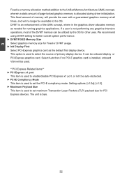
... user with a guaranteed graphics memory at all times, and will be used. **PCI Express Related items** ► PCI Express x1 port This item is used to enable/disable PCI Express x1 port, or let it be available to the OS. Select Auto then if no PCI-E graphics card is installed, onboard VGA will no longer be auto-dectected. ► PCI-E Compliancy Mode This item is used to set maximum Transaction Layer Packets (TLP) payload size for other uses. If a user...
... user with a guaranteed graphics memory at all times, and will be used. **PCI Express Related items** ► PCI Express x1 port This item is used to enable/disable PCI Express x1 port, or let it be available to the OS. Select Auto then if no PCI-E graphics card is installed, onboard VGA will no longer be auto-dectected. ► PCI-E Compliancy Mode This item is used to set maximum Transaction Layer Packets (TLP) payload size for other uses. If a user...
English Manual.
Page 41
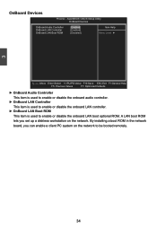
... CMOS Setup Utility OnBoard Devices OnBoard Audio Controller OnBoard LAN Controller OnBoard LAN Boot ROM [Enabled] Item Help [Enabled] [Disabled] Menu Level ► Move Enter:Select +/-/PU/PD:Value F10:Save ESC:Exit F1:General Help F5: Previous Values F7: Optimized Defaults ► OnBoard Audio Controller This item is used to enable or disable the onboard audio controller. ► OnBoard LAN Controller This item is used to enable or disable the onboard LAN controller. ► OnBoard LAN Boot ROM This item is used to be booted remotely. 34 By installing a boot ROM...
... CMOS Setup Utility OnBoard Devices OnBoard Audio Controller OnBoard LAN Controller OnBoard LAN Boot ROM [Enabled] Item Help [Enabled] [Disabled] Menu Level ► Move Enter:Select +/-/PU/PD:Value F10:Save ESC:Exit F1:General Help F5: Previous Values F7: Optimized Defaults ► OnBoard Audio Controller This item is used to enable or disable the onboard audio controller. ► OnBoard LAN Controller This item is used to enable or disable the onboard LAN controller. ► OnBoard LAN Boot ROM This item is used to be booted remotely. 34 By installing a boot ROM...

English Manual.
Page 43
... is used to auto or enabled. ► ***USB Mass Storage Device Boot Setting*** BIOS auto detects the presence of USB Mass Storage Devices, you select the [High Speed], then the USB operation mode is used to set to enable the support for USB mouse on legacy OS. Setting Options: [Auto]; [FDD Mode]; [HDD Mode] 36 Move Enter:Select +/-/PU/PD:Value F10:Save ESC:Exit F1:General Help F5: Previous Values F7: Optimized Defaults ► USB 1.1 Controller This item is used to enable or disable the...
... is used to auto or enabled. ► ***USB Mass Storage Device Boot Setting*** BIOS auto detects the presence of USB Mass Storage Devices, you select the [High Speed], then the USB operation mode is used to set to enable the support for USB mouse on legacy OS. Setting Options: [Auto]; [FDD Mode]; [HDD Mode] 36 Move Enter:Select +/-/PU/PD:Value F10:Save ESC:Exit F1:General Help F5: Previous Values F7: Optimized Defaults ► USB 1.1 Controller This item is used to enable or disable the...

English Manual.
Page 44
..." off ] [Off] [Enabled] [Disabled] 0 0 : 0: 0 ** Power Management Related Items ** HPET Support [Enabled] HPET Mode [32-bit mode] USB Wake Up from S3 [Disabled] Power On by Mouse [Disabled] Power On by Keyboard [Disabled] x KB Power On Password Enter x Hot Key Power On Ctrl-F1 Move Enter:Select +/-/PU/PD:Value F10:Save ESC:Exit F1:General Help F5: Previous Values F7: Optimized Defaults 3 ACPI (Advanced Configuration and Power Interface) is similar to Disk) S5 - ACPI defines five sleeping states, they...
..." off ] [Off] [Enabled] [Disabled] 0 0 : 0: 0 ** Power Management Related Items ** HPET Support [Enabled] HPET Mode [32-bit mode] USB Wake Up from S3 [Disabled] Power On by Mouse [Disabled] Power On by Keyboard [Disabled] x KB Power On Password Enter x Hot Key Power On Ctrl-F1 Move Enter:Select +/-/PU/PD:Value F10:Save ESC:Exit F1:General Help F5: Previous Values F7: Optimized Defaults 3 ACPI (Advanced Configuration and Power Interface) is similar to Disk) S5 - ACPI defines five sleeping states, they...
English Manual.
Page 47
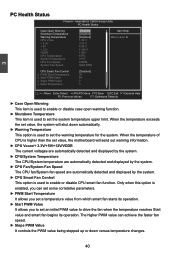
AwardBIOS CMOS Setup Utility PC Health Status Case Open Warning [Disabled] Item Help Shutdown Temperature [Disabled] Warning Temperature [Disabled] Menu Level ► CPU Vcore 1.26 V + 3.3V 3.37 V + 5V 4.99 V + 12V 11.84 V VDDR CPU Temperature System Temperature 1.90V 61oC 31oC CPU Fan Speed 0 RPM System Fan Speed 3648 RPM CPU Smart Fan Control [Disabled] x PWM Start Temperature 35 x Start PWM Value 64 x Slope PWM Value 2 x Delta Temperature 3 Move Enter:Select +/-/PU/PD:Value F10:Save ESC:Exit ...
AwardBIOS CMOS Setup Utility PC Health Status Case Open Warning [Disabled] Item Help Shutdown Temperature [Disabled] Warning Temperature [Disabled] Menu Level ► CPU Vcore 1.26 V + 3.3V 3.37 V + 5V 4.99 V + 12V 11.84 V VDDR CPU Temperature System Temperature 1.90V 61oC 31oC CPU Fan Speed 0 RPM System Fan Speed 3648 RPM CPU Smart Fan Control [Disabled] x PWM Start Temperature 35 x Start PWM Value 64 x Slope PWM Value 2 x Delta Temperature 3 Move Enter:Select +/-/PU/PD:Value F10:Save ESC:Exit ...
English Manual.
Page 48
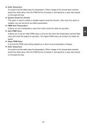
... controls the PWM value being stepped up or down versus temperature changes. ► Delta Temperture It is enabled, you can set some correlative parameters. ► PWM Start Temperature It allows you set a temperature value from which smart fan starts its operation. ► Start PWM Value It allows you to set an initial PWM value to enable or disable system smart fan function. Only when this option is used to drive the fan...
... controls the PWM value being stepped up or down versus temperature changes. ► Delta Temperture It is enabled, you can set some correlative parameters. ► PWM Start Temperature It allows you set a temperature value from which smart fan starts its operation. ► Start PWM Value It allows you to set an initial PWM value to enable or disable system smart fan function. Only when this option is used to drive the fan...
English Manual.
Page 51
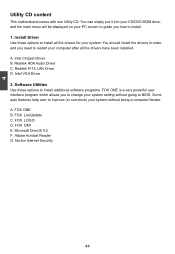
... G. 4 Utility CD content This motherboard comes with one Utility CD. A. Realtek HDA Audio Driver C. Intel VGA Driver 2. You should install the drivers in order, and you need to improve (or overclock) your PC screen to guide you to change your system. A. Software Utilities Use these options to install. 1. FOX LOGO D. You can simply put it into your CD/DVD-ROM drive, and the main menu will be displayed on your system without going to BIOS...
... G. 4 Utility CD content This motherboard comes with one Utility CD. A. Realtek HDA Audio Driver C. Intel VGA Driver 2. You should install the drivers in order, and you need to improve (or overclock) your PC screen to guide you to change your system. A. Software Utilities Use these options to install. 1. FOX LOGO D. You can simply put it into your CD/DVD-ROM drive, and the main menu will be displayed on your system without going to BIOS...


