English Manual.
Page 6
... CPU Cooler 8 Install the Memory 10 Install an Expansion Card 12 Install other Internal Connectors 13 Jumpers 17 Chapter 3 BIOS Setup Enter BIOS Setup 19 Main Menu 19 System Information 21 Boot Setting Configuration 24 Advanced Chipset Features 26 Integrated Peripherals 30 Power Management... 33 Hardware Monitor 35 Overclock Control Center 36 BIOS Security Features 47 Load Optimal Defaults 48 Save & Exit Setup 48 Exit without Saving 48 Chapter 4 CD Instruction Utility CD...
... CPU Cooler 8 Install the Memory 10 Install an Expansion Card 12 Install other Internal Connectors 13 Jumpers 17 Chapter 3 BIOS Setup Enter BIOS Setup 19 Main Menu 19 System Information 21 Boot Setting Configuration 24 Advanced Chipset Features 26 Integrated Peripherals 30 Power Management... 33 Hardware Monitor 35 Overclock Control Center 36 BIOS Security Features 47 Load Optimal Defaults 48 Save & Exit Setup 48 Exit without Saving 48 Chapter 4 CD Instruction Utility CD...

English Manual.
Page 7
... FOX LOGO 72 FOX DMI 73 Chapter 5 RAID Configuration RAID Configuration Introduction 76 Option ROM Utility 78 Create a RAID Driver Diskette 80 RAID Enable in BIOS 82 Select a RAID Array for Use 82 Install a New Windows XP 95 Setting Up a Non-Bootable RAID Array 99 Appendix -
... FOX LOGO 72 FOX DMI 73 Chapter 5 RAID Configuration RAID Configuration Introduction 76 Option ROM Utility 78 Create a RAID Driver Diskette 80 RAID Enable in BIOS 82 Select a RAID Array for Use 82 Install a New Windows XP 95 Setting Up a Non-Bootable RAID Array 99 Appendix -

English Manual.
Page 17
When memory is installed, the BIOS will automatically check the memory in only one direction. DS/SS - CAUTION 10 DS/SS - Dual Channel - - DS/SS DS/SS ! It is recommended that ...
When memory is installed, the BIOS will automatically check the memory in only one direction. DS/SS - CAUTION 10 DS/SS - Dual Channel - - DS/SS DS/SS ! It is recommended that ...

English Manual.
Page 19
... that supports your computer. Install the driver provided with a screw. 5. Secure the card's metal bracket to make any required BIOS changes for your expansion card in the expansion slot. 1. If necessary, go to BIOS Setup to the chassis back panel with the expansion card in the slot. 3. 2 CAUTION 2-3 Install an Expansion Card...
... that supports your computer. Install the driver provided with a screw. 5. Secure the card's metal bracket to make any required BIOS changes for your expansion card in the expansion slot. 1. If necessary, go to BIOS Setup to the chassis back panel with the expansion card in the slot. 3. 2 CAUTION 2-3 Install an Expansion Card...

English Manual.
Page 23
... choice. S/PDIF Out Connector : SPDIF_OUT The connector is a Sony standard audio connector, it can be controlled and monitored in "PC Health Status" section of the BIOS Setup. These fans can be connected to a CD/DVD-ROM drive through a CD/DVD audio cable. Fan Headers : CPU_FAN, SYS_FAN, FAN1, FAN2 There are five...
... choice. S/PDIF Out Connector : SPDIF_OUT The connector is a Sony standard audio connector, it can be controlled and monitored in "PC Health Status" section of the BIOS Setup. These fans can be connected to a CD/DVD-ROM drive through a CD/DVD audio cable. Fan Headers : CPU_FAN, SYS_FAN, FAN1, FAN2 There are five...

English Manual.
Page 24
...Pin 2 closed Set Pin 2 and Pin 3 closed Set two pins closed . 4. Plug in the power cord to factory default when the BIOS settings were mistakenly modified. This section explains how to store the basic hardware information (such as described in this motherboard by changing the jumper ...settings. For any jumper setting. The steps to modifying any jumper on this motherboard to configure new system as BIOS data, date, time information, hardware password...etc.). Go to BIOS Setup to modify them . Description of the jumper settings. This will clear CMOS data. 3. Users should ...
...Pin 2 closed Set Pin 2 and Pin 3 closed Set two pins closed . 4. Plug in the power cord to factory default when the BIOS settings were mistakenly modified. This section explains how to store the basic hardware information (such as described in this motherboard by changing the jumper ...settings. For any jumper setting. The steps to modifying any jumper on this motherboard to configure new system as BIOS data, date, time information, hardware password...etc.). Go to BIOS Setup to modify them . Description of the jumper settings. This will clear CMOS data. 3. Users should ...
English Manual.
Page 25
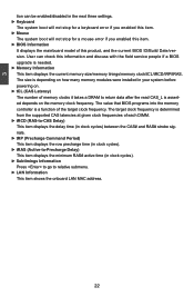
... Power Management ■ Hardware Monitor ■ Overclock Control Center ■ BIOS Security Features ■ Load Optimal Defaults ■ Save & Exit Setup ■ Exit without Saving Since BIOS could be updated some other times, the BIOS information described in the future. An error message appears on the screen during...includes the following cases occur: 1. You have to change the default CMOS settings. You want to change system settings through the BIOS Setup menus. Please visit our website for updated manual if it is for reference only. We do not guarantee the content of the...
... Power Management ■ Hardware Monitor ■ Overclock Control Center ■ BIOS Security Features ■ Load Optimal Defaults ■ Save & Exit Setup ■ Exit without Saving Since BIOS could be updated some other times, the BIOS information described in the future. An error message appears on the screen during...includes the following cases occur: 1. You have to change the default CMOS settings. You want to change system settings through the BIOS Setup menus. Please visit our website for updated manual if it is for reference only. We do not guarantee the content of the...
English Manual.
Page 26
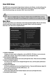
...Copyright (C) 1985-2009, American Megatrends, Inc. ► System Information ► Overclock Control Center ► Boot Setting Configuration ► BIOS Security Features ► Advanced Chipset Features Load Optimal Defaults ► Integrated Peripherals Save & Exit Setup ► Power Management Setup Exit...American Megatrends, Inc. ► System Information It displays the basic system configuration, such as Serial I /O devices such as BIOS ID, CPU Name, memory size plus system date, and time. There are boot up settings. ► Advanced Chipset Features ...
...Copyright (C) 1985-2009, American Megatrends, Inc. ► System Information ► Overclock Control Center ► Boot Setting Configuration ► BIOS Security Features ► Advanced Chipset Features Load Optimal Defaults ► Integrated Peripherals Save & Exit Setup ► Power Management Setup Exit...American Megatrends, Inc. ► System Information It displays the basic system configuration, such as Serial I /O devices such as BIOS ID, CPU Name, memory size plus system date, and time. There are boot up settings. ► Advanced Chipset Features ...

English Manual.
Page 27
... in correct password before boot or access to read/change anything and exit the setup. 20 It means, if your system loading is to adjust BIOS setting one by one, trial and error, to find out the best setting for your current system. ► Save & Exit Setup Save setting values to... CMOS and exit. ► Exit Without Saving Do not change Fan speeds, and displays temperatures and voltages of your CPU/System. ► BIOS Security Features The Supervisor/User password can be set to optimal default may cause problem if you need now is heavy, set up through this...
... in correct password before boot or access to read/change anything and exit the setup. 20 It means, if your system loading is to adjust BIOS setting one by one, trial and error, to find out the best setting for your current system. ► Save & Exit Setup Save setting values to... CMOS and exit. ► Exit Without Saving Do not change Fan speeds, and displays temperatures and voltages of your CPU/System. ► BIOS Security Features The Supervisor/User password can be set to optimal default may cause problem if you need now is heavy, set up through this...

English Manual.
Page 28
... : : respectively. ► Date (mm:dd:yy) format. System Information This sub-menu is used to set up the standard BIOS features, such as the date, time, floppy drive and so on the motherboard. ► Halt On This category determines whether or ...Detected] Use [+] or [-] to [Not Detected] configure the system time. [All Errors, But ...] [Disabled] [Disabled] System Overview BIOS Information Mainboard Model BIOS ID BIOS Build Date : Cinema II : 941F1P01 : 07/01/09 Move Enter:Select +/-/:Value F10:Save ESC:Exit F1:General Help F2/F3:Change Colors F9:Optimized Defaults...
... : : respectively. ► Date (mm:dd:yy) format. System Information This sub-menu is used to set up the standard BIOS features, such as the date, time, floppy drive and so on the motherboard. ► Halt On This category determines whether or ...Detected] Use [+] or [-] to [Not Detected] configure the system time. [All Errors, But ...] [Disabled] [Disabled] System Overview BIOS Information Mainboard Model BIOS ID BIOS Build Date : Cinema II : 941F1P01 : 07/01/09 Move Enter:Select +/-/:Value F10:Save ESC:Exit F1:General Help F2/F3:Change Colors F9:Optimized Defaults...
English Manual.
Page 29
... frequency is determined from the supported CAS latencies at given clock frequencies of this information and discuss with the field service people if a BIOS upgrade is needed. ► Memory Information This item displays the current memory size/memory tinings/memory clock/tCL/tRCD/tRP/tRAS. The ...). ► Subtimings Information Press to go to return data after the read CAS_L is depending on the memory clock frequency. The value that BIOS programs into the memory controller is a function of memory clocks it takes a DRAM to relative submenu. ► LAN Information This item shows...
... frequency is determined from the supported CAS latencies at given clock frequencies of this information and discuss with the field service people if a BIOS upgrade is needed. ► Memory Information This item displays the current memory size/memory tinings/memory clock/tCL/tRCD/tRP/tRAS. The ...). ► Subtimings Information Press to go to return data after the read CAS_L is depending on the memory clock frequency. The value that BIOS programs into the memory controller is a function of memory clocks it takes a DRAM to relative submenu. ► LAN Information This item shows...

English Manual.
Page 31
... the secondary PCI bus on a motherboard that doesn't come with support for improved support of POST messages. ► Quick Boot While Enabled, this option allows BIOS to skip certain tests while booting, this will shorten the time needed to make use . Boot Setting Configuration Smart Boot Menu IDE Detect Time Out...
... the secondary PCI bus on a motherboard that doesn't come with support for improved support of POST messages. ► Quick Boot While Enabled, this option allows BIOS to skip certain tests while booting, this will shorten the time needed to make use . Boot Setting Configuration Smart Boot Menu IDE Detect Time Out...

English Manual.
Page 34
Select [Auto], RC will turn off Generation II speed mode of PCI Express slots. ► Link ASPM This item is used to select the link mode between ASPMs. ► Link Width This item ...; You can use [+]/ [-] to change the value or directly input a value from 0 to select the Generation II speed mode of PCI Express slots. Copyright (C) 1985-2009, American Megatrends, Inc. Select [Disabled], BIOS will only advertize Generation II capability; Select [Software Initiated], the speed mode is [75]. 27 Select [Advertised RC], the speed mode...
Select [Auto], RC will turn off Generation II speed mode of PCI Express slots. ► Link ASPM This item is used to select the link mode between ASPMs. ► Link Width This item ...; You can use [+]/ [-] to change the value or directly input a value from 0 to select the Generation II speed mode of PCI Express slots. Copyright (C) 1985-2009, American Megatrends, Inc. Select [Disabled], BIOS will only advertize Generation II capability; Select [Software Initiated], the speed mode is [75]. 27 Select [Advertised RC], the speed mode...

English Manual.
Page 35
Select [Auto], RC will turn off Generation II speed mode of PCI Express slots. ► Link ASPM This item is used to select the link mode between ASPMs. ! Copyright (C) 1985-2005, American Megatrends, ... Defaults ► Gen2 High Speed Mode This item is determined by software initiated; Select [Advertised RC], the speed mode is used to select the Generation II speed mode of PCI Express slots. The item of the PCIe #6. 28 Select [Software Initiated], the speed mode is the same of the PCIe Port...
Select [Auto], RC will turn off Generation II speed mode of PCI Express slots. ► Link ASPM This item is used to select the link mode between ASPMs. ! Copyright (C) 1985-2005, American Megatrends, ... Defaults ► Gen2 High Speed Mode This item is determined by software initiated; Select [Advertised RC], the speed mode is used to select the Generation II speed mode of PCI Express slots. The item of the PCIe #6. 28 Select [Software Initiated], the speed mode is the same of the PCIe Port...

English Manual.
Page 39
...be selected. 32 If USB devices are connected to enable support for legacy USB. If you can be available in 12Mbps. ► BIOS EHCI Hand-Off Windows XP supports a number of USB 2.0. USB Configuration USB Configuration Help Item Module Version - 2.24.5-13.4 USB ...Device Enabled : 1 Keyboard Legacy USB Support USB 2.0 Controller Mode BIOS EHCI Hand-Off [Enabled] [HiSpeed] [Enabled] Enabled support for OS without EHCI hand-Off support . The available settings are not implemented. ...
...be selected. 32 If USB devices are connected to enable support for legacy USB. If you can be available in 12Mbps. ► BIOS EHCI Hand-Off Windows XP supports a number of USB 2.0. USB Configuration USB Configuration Help Item Module Version - 2.24.5-13.4 USB ...Device Enabled : 1 Keyboard Legacy USB Support USB 2.0 Controller Mode BIOS EHCI Hand-Off [Enabled] [HiSpeed] [Enabled] Enabled support for OS without EHCI hand-Off support . The available settings are not implemented. ...

English Manual.
Page 40
.... 33 S3 - Software uses a different state value to distinguish between the S5 state and the S4 state to allow for initial boot operations within the BIOS to distinguish whether or not the boot is assumed that the CPU and system cache context is lost except system memory. The S1 sleeping state...
.... 33 S3 - Software uses a different state value to distinguish between the S5 state and the S4 state to allow for initial boot operations within the BIOS to distinguish whether or not the boot is assumed that the CPU and system cache context is lost except system memory. The S1 sleeping state...
English Manual.
Page 47
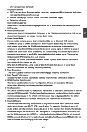
... the read CAS_L is asserted depends on the memory clock frequency. Copyright (C) 1985-2009, American Megatrends, Inc. The value that BIOS programs into the memory controller is used to PRECHARGE Command delay 40 The target clock frequency is used to configuation Memory Frequency,Timings and... Subtimings. Memory Configuration CMOS Setup Utility - Setting values are enabled in unganged mode, BIOS must initialize the frequency of each DIMM. ► tRCD (RAS-to-CAS Delay) This item allows you to select a delay time (...
... the read CAS_L is asserted depends on the memory clock frequency. Copyright (C) 1985-2009, American Megatrends, Inc. The value that BIOS programs into the memory controller is used to PRECHARGE Command delay 40 The target clock frequency is used to configuation Memory Frequency,Timings and... Subtimings. Memory Configuration CMOS Setup Utility - Setting values are enabled in unganged mode, BIOS must initialize the frequency of each DIMM. ► tRCD (RAS-to-CAS Delay) This item allows you to select a delay time (...

English Manual.
Page 49
... used to have identical size and timing parameters, both Channel 0 and Channel 1 memory channels ► Enable Clock to All DIMMs This setting is enabled, the BIOS can deal with those storage cells. Dual channel (Interleaved) mode offers the highest throughput for DRAM Controller. PCI doesn't actually care much RAM into the...
... used to have identical size and timing parameters, both Channel 0 and Channel 1 memory channels ► Enable Clock to All DIMMs This setting is enabled, the BIOS can deal with those storage cells. Dual channel (Interleaved) mode offers the highest throughput for DRAM Controller. PCI doesn't actually care much RAM into the...
English Manual.
Page 50
...control. Unganged channels ■ DCT channels A and B operate as two completely independent 64-bit channels (both DCTs are enabled in unganged mode, BIOS must convert the tFAW parameter into MEMCLK cycles by dividing the highest tFAW (in ns) across all DIMMs connected to the channel by deasserting the... ► Page Smashing This item is used to set the memory configuration. Burst lengths supported When both chan- For example, if this field, BIOS must initialize the frequency of the DIMMs connected to the next integer. 43 A DIMM or a group of MEMCLK (in order to [Channel]...
...control. Unganged channels ■ DCT channels A and B operate as two completely independent 64-bit channels (both DCTs are enabled in unganged mode, BIOS must convert the tFAW parameter into MEMCLK cycles by dividing the highest tFAW (in ns) across all DIMMs connected to the channel by deasserting the... ► Page Smashing This item is used to set the memory configuration. Burst lengths supported When both chan- For example, if this field, BIOS must initialize the frequency of the DIMMs connected to the next integer. 43 A DIMM or a group of MEMCLK (in order to [Channel]...

English Manual.
Page 51
... 4-Bit ECC Mode [Disabled] dynamically sets the DRAM BG Scrub [Disabled] DRAM scrub rate so Data Cache BG Scrub [Disabled] all of memory is enabled, BIOS will force DRAM scrub off.) ► Data Cache BG Scrub It allows the L1 Data Cache ram to be corrected while idle. ► L2 Cache...
... 4-Bit ECC Mode [Disabled] dynamically sets the DRAM BG Scrub [Disabled] DRAM scrub rate so Data Cache BG Scrub [Disabled] all of memory is enabled, BIOS will force DRAM scrub off.) ► Data Cache BG Scrub It allows the L1 Data Cache ram to be corrected while idle. ► L2 Cache...


