User Manual
Page 3
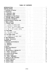
... paper holder 7.2.2. Gap Adjustment 9. Indicators 2. Buzzer 3. Construction of fanfold paper 7.1.2. Control circuit board 5.3. Repacking steps 3. Loading of MX-80 F/T 5.1. Loading of DIP Switches 7. Power Connection OPERATION 1. Switches 1.2. Printer initialization 6. Unpacking steps 2.2. Column layout on fanfold paper. .. 7.1.4. Roll paper 7.2.1. Setting of roll paper 7.3. TABLE OF CONTENTS INTRODUCTION INSTALLATION 1. Contents of fanfold paper 7.1.3. Unpacking 2.1. Cartridge Ribbon Setting 5. Separator Installation 6. Removal...
... paper holder 7.2.2. Gap Adjustment 9. Indicators 2. Buzzer 3. Construction of fanfold paper 7.1.2. Control circuit board 5.3. Repacking steps 3. Loading of MX-80 F/T 5.1. Loading of DIP Switches 7. Power Connection OPERATION 1. Switches 1.2. Printer initialization 6. Unpacking steps 2.2. Column layout on fanfold paper. .. 7.1.4. Roll paper 7.2.1. Setting of roll paper 7.3. TABLE OF CONTENTS INTRODUCTION INSTALLATION 1. Contents of fanfold paper 7.1.3. Unpacking 2.1. Cartridge Ribbon Setting 5. Separator Installation 6. Removal...
User Manual
Page 5
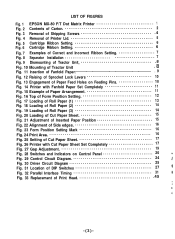
... Paper Sheet 15 Fig. 21 Adjustment of Inserted Paper Position 15 Fig. 22 Alignment of Side edges 16 Fig. 23 Form Position Setting Mark 16 Fig. 24 Print Area 16 Fig. 25 Setting of Cut Paper Sheet 17 Fig. 26 Printer with Cut Paper Sheet Set Completely 17 Fig. 27 Gap Adjustment 19 Fig. 28 Switches and Indicators on Control Panel 20 Fig. 29 Control Circuit Diagram 24 Fig. 30 Driver Circuit Diagram...
... Paper Sheet 15 Fig. 21 Adjustment of Inserted Paper Position 15 Fig. 22 Alignment of Side edges 16 Fig. 23 Form Position Setting Mark 16 Fig. 24 Print Area 16 Fig. 25 Setting of Cut Paper Sheet 17 Fig. 26 Printer with Cut Paper Sheet Set Completely 17 Fig. 27 Gap Adjustment 19 Fig. 28 Switches and Indicators on Control Panel 20 Fig. 29 Control Circuit Diagram 24 Fig. 30 Driver Circuit Diagram...
User Manual
Page 7
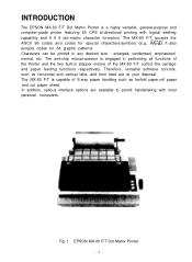
... permit handshaking with logical seeking capability and 9 X 9 dot-matrix character formation. INTRODUCTION The EPSON MX-80 F/T Dot Matrix Printer is a highly versatile, general-purpose and computer-grade printer featuring 80 CPS bi-directional printing with most personal computers. The MX-80 F/T accepts the ASCII 96 codes and codes for 64 graphic patterns. C 2). The MX-80 F/T is capable of the MX-80 F/T control the carriage and paper feeding functions respectively.
... permit handshaking with logical seeking capability and 9 X 9 dot-matrix character formation. INTRODUCTION The EPSON MX-80 F/T Dot Matrix Printer is a highly versatile, general-purpose and computer-grade printer featuring 80 CPS bi-directional printing with most personal computers. The MX-80 F/T accepts the ASCII 96 codes and codes for 64 graphic patterns. C 2). The MX-80 F/T is capable of the MX-80 F/T control the carriage and paper feeding functions respectively.

User Manual
Page 8
Cartridge Ribbon 1 4. INSTALLATION 1. Upon unpacking, if you purchased the MX-80 F/T as soon as shown in Fig. 2. MX-80 F/T 1 2. MX-80 F/T Operation Manual 1 ] Fig. 2 Contents of Carton The MX-80 F/T and standard accessories are as possible. 1 Power Cord (European Type) Operation Manual MX-80 F/T Dot Matrix Printer 1. contact the store where you notice any listed contents missing or evident damage. Power Cord (Only European Type 220/240V) 1 5. Contents of Carton -2- Separator 1 3.
Cartridge Ribbon 1 4. INSTALLATION 1. Upon unpacking, if you purchased the MX-80 F/T as soon as shown in Fig. 2. MX-80 F/T 1 2. MX-80 F/T Operation Manual 1 ] Fig. 2 Contents of Carton The MX-80 F/T and standard accessories are as possible. 1 Power Cord (European Type) Operation Manual MX-80 F/T Dot Matrix Printer 1. contact the store where you notice any listed contents missing or evident damage. Power Cord (Only European Type 220/240V) 1 5. Contents of Carton -2- Separator 1 3.

User Manual
Page 9
... 3. Take off the packing material carefully. Installation of greasy dust exists in the future. 3. 2. Open the carton. Unpacking Before removing the MX-80 F/T from those connected to noise-generating equipment, such as large-power motors, refrigerators, etc. (d) Do not subject the Printer to an outlet separated from the carton, check the box for repair, storage, etc.) NOTE: It is present...
... 3. Take off the packing material carefully. Installation of greasy dust exists in the future. 3. 2. Open the carton. Unpacking Before removing the MX-80 F/T from those connected to noise-generating equipment, such as large-power motors, refrigerators, etc. (d) Do not subject the Printer to an outlet separated from the carton, check the box for repair, storage, etc.) NOTE: It is present...
User Manual
Page 15
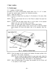
... paper guide roller is at the center of the sprocket shaft, If not, set it in the direction of the head adjusting lever in width. STEP 2. Unlock the release lever by pulling it at the rear part of Fanfold Paper STEP 6. Paper Loading 7.1. Adjust the position of the arrow. (See Fig. 11.) STEP 3. After the leading edge of fanfold paper The MX-80 F/T Printer accommodates fanfold paper...
... paper guide roller is at the center of the sprocket shaft, If not, set it in the direction of the head adjusting lever in width. STEP 2. Unlock the release lever by pulling it at the rear part of Fanfold Paper STEP 6. Paper Loading 7.1. Adjust the position of the arrow. (See Fig. 11.) STEP 3. After the leading edge of fanfold paper The MX-80 F/T Printer accommodates fanfold paper...
User Manual
Page 17
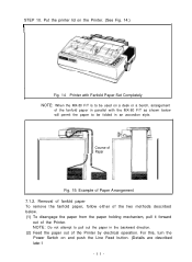
.... 14 Printer with the MX-80 F/T as shown below . (1) To disengage the paper from the paper holding mechanism, pull it forward out of the Printer by electrical operation. Course of Paper Fig. 15: Example of the fanfold paper in parallel with Fanfold Paper Set Completely NOTE: When the MX-80 F/T is to pull out the paper in an accordion style. For this, turn the Power Switch on...
.... 14 Printer with the MX-80 F/T as shown below . (1) To disengage the paper from the paper holding mechanism, pull it forward out of the Printer by electrical operation. Course of Paper Fig. 15: Example of the fanfold paper in parallel with Fanfold Paper Set Completely NOTE: When the MX-80 F/T is to pull out the paper in an accordion style. For this, turn the Power Switch on...
User Manual
Page 18
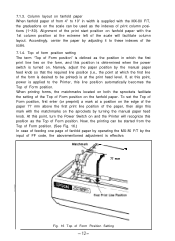
... Fig. 16 Top of FF code, the abovementioned adjustment is effective. At this point, turn the Power Switch on and the Printer will facilitate column layout. Alignment of the print start position on fanfold paper with the 1st column position at a position on the scale can be started from 4" to the Printer, this mark with the MX-80 F/T, the graduations on the...
... Fig. 16 Top of FF code, the abovementioned adjustment is effective. At this point, turn the Power Switch on and the Printer will facilitate column layout. Alignment of the print start position on fanfold paper with the 1st column position at a position on the scale can be started from 4" to the Printer, this mark with the MX-80 F/T, the graduations on the...
User Manual
Page 19
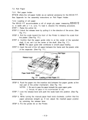
... and the plastic roller of the arrow. (See Fig. 17.) STEP 3. Roll Paper 7.2.1. Roll paper holder EPSON offers the roll paper holder as an optional accessory for the assembly instructions on the Printer. -13- See Appendix for the MX-80 F/T. core. To load it in the direction of the separator. (See Fig. 17.) STEP 6. If not, adjust the inserted paper position by pulling...
... and the plastic roller of the arrow. (See Fig. 17.) STEP 3. Roll Paper 7.2.1. Roll paper holder EPSON offers the roll paper holder as an optional accessory for the assembly instructions on the Printer. -13- See Appendix for the MX-80 F/T. core. To load it in the direction of the separator. (See Fig. 17.) STEP 6. If not, adjust the inserted paper position by pulling...
User Manual
Page 20
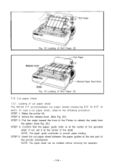
... paper sheet between the paper guides at the rear part of the shaft. STEP 2. NOTE: The paper sheet can be installed without removing the separator. -14- STEP 1. If not, set it at the center of cut paper sheet The MX-80 F/T accommodates cut paper sheets measuring 8.3" to smooth paper feeding. Loading of the sprocket shaft. Pull the scale toward the front of Roll Paper (3) 7.3. Roll Paper Fig. 18 Loading of Roll Paper (2) Roll Paper Manual Paper Feed...
... paper sheet between the paper guides at the rear part of the shaft. STEP 2. NOTE: The paper sheet can be installed without removing the separator. -14- STEP 1. If not, set it at the center of cut paper sheet The MX-80 F/T accommodates cut paper sheets measuring 8.3" to smooth paper feeding. Loading of the sprocket shaft. Pull the scale toward the front of Roll Paper (3) 7.3. Roll Paper Fig. 18 Loading of Roll Paper (2) Roll Paper Manual Paper Feed...
User Manual
Page 24
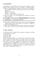
... a replacement unit with the effects described in the@direction) by one step. (See Fig. 27.) (4) When a set of the Printer. NOTE: With a thick paper, be sure that no characters are printed within the area two lines each above and below the perforation. 9. Set the lever to the 7th step. (3) Should printed characters become faint due to the 4th step. Power Connection The EPSON MX-80...
... a replacement unit with the effects described in the@direction) by one step. (See Fig. 27.) (4) When a set of the Printer. NOTE: With a thick paper, be sure that no characters are printed within the area two lines each above and below the perforation. 9. Set the lever to the 7th step. (3) Should printed characters become faint due to the 4th step. Power Connection The EPSON MX-80...

User Manual
Page 26
... this section, panel operating procedures are covered in sufficient detail for the control panel.) Power Switch Fig. 28 Switches and Indicators on the paper. Incorrect setting of the Printer case. ON LINE SW: When this switch on the right side of the paper may prevent the Printer from operating properly. However, if the ON LINE switch is printed immediately. This is helpful to then is turned off, the data stored in the OFF-LINE mode.
... this section, panel operating procedures are covered in sufficient detail for the control panel.) Power Switch Fig. 28 Switches and Indicators on the paper. Incorrect setting of the Printer case. ON LINE SW: When this switch on the right side of the paper may prevent the Printer from operating properly. However, if the ON LINE switch is printed immediately. This is helpful to then is turned off, the data stored in the OFF-LINE mode.

User Manual
Page 27
... paper supply is in printing. 1.2. Error status: It sounds intermittently for about 30 seconds when the Printer falls into error status. I tions. 3. When the POWER switch is on or when INIT signal is applied to the interface connector. FF SW: (Form Feed) LF SW: (Line Feed) When this switch is being depressed. Therefore, before turning the POWER switch on the interface connector change to start operating the Printer, set the paper...
... paper supply is in printing. 1.2. Error status: It sounds intermittently for about 30 seconds when the Printer falls into error status. I tions. 3. When the POWER switch is on or when INIT signal is applied to the interface connector. FF SW: (Form Feed) LF SW: (Line Feed) When this switch is being depressed. Therefore, before turning the POWER switch on the interface connector change to start operating the Printer, set the paper...

User Manual
Page 28
... check all previously established data such as follows: (a) Connect ACKNLG signal pin No. 10 to effect auto-line feed. -22- are printed out on the control circuit board) ON to STROBE signal pin No. 1 with a lead wire. (b) Turn the DIP switch 2-3 (on the paper by depressing the LF switch. The self-test function cannot be performed by the internal software are erased. 4. In this operation...
... check all previously established data such as follows: (a) Connect ACKNLG signal pin No. 10 to effect auto-line feed. -22- are printed out on the control circuit board) ON to STROBE signal pin No. 1 with a lead wire. (b) Turn the DIP switch 2-3 (on the paper by depressing the LF switch. The self-test function cannot be performed by the internal software are erased. 4. In this operation...

User Manual
Page 29
... model 3310 printer mechanism (2) Control circuit board (3) Power circuit These three blocks are connected to form 9 X 9 dot matrix characters. 9 wires form more legible characters than those formed by the stepper motor, like the head carriage. The CPU knows the current printing position at the last printing position. In the MX-80 F/T, the operator can select any given time, and the print head is controlled under software control...
... model 3310 printer mechanism (2) Control circuit board (3) Power circuit These three blocks are connected to form 9 X 9 dot matrix characters. 9 wires form more legible characters than those formed by the stepper motor, like the head carriage. The CPU knows the current printing position at the last printing position. In the MX-80 F/T, the operator can select any given time, and the print head is controlled under software control...

User Manual
Page 32
... turning the Power Switch off and on the rear side of the lower case of the two ways described below. (1) Initialization takes place automatically each time the primary AC power source is reset to the parallel interface connector. NOTE: The form length of 72 lines per page is set to energize the solenoids of paper. (c) The print buffer is cleared. (d) The line spacing is set...
... turning the Power Switch off and on the rear side of the lower case of the two ways described below. (1) Initialization takes place automatically each time the primary AC power source is reset to the parallel interface connector. NOTE: The form length of 72 lines per page is set to energize the solenoids of paper. (c) The print buffer is cleared. (d) The line spacing is set...

User Manual
Page 36
... used . Data entry to the printer is reset to be more than 0.2 /.Ls. 4. "Direction" refers to the direction of the BUSY signal is set "LOW' for each signal must not be carried out by ignoring the ACKNLG or BUSY signal. (Data transfer to 30. Pin No. All interface conditions are based on the Return side. When the level of shipment is "LOW".) -30- Data transfer...
... used . Data entry to the printer is reset to be more than 0.2 /.Ls. 4. "Direction" refers to the direction of the BUSY signal is set "LOW' for each signal must not be carried out by ignoring the ACKNLG or BUSY signal. (Data transfer to 30. Pin No. All interface conditions are based on the Return side. When the level of shipment is "LOW".) -30- Data transfer...
User Manual
Page 45
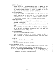
... of paper. When the power is turned on, the Printer is no paper. 6) ESC SI This code functions the same as "SI." 7) ESC SO This code functions the same as data. The ESC 2 code is also a command to execute "ESC A+n" modes (described later). 4) ESC 8(Escape 8) The ESC 8 code makes it possible to transmit data even if there is initialized into ESC 9 status. the ERROR signal...
... of paper. When the power is turned on, the Printer is no paper. 6) ESC SI This code functions the same as "SI." 7) ESC SO This code functions the same as data. The ESC 2 code is also a command to execute "ESC A+n" modes (described later). 4) ESC 8(Escape 8) The ESC 8 code makes it possible to transmit data even if there is initialized into ESC 9 status. the ERROR signal...
User Manual
Page 50
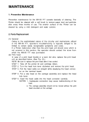
... the MX-80 F/T, operator's troubleshooting is logically obliged to certain easily recognizable symptoms and cures. Turn the head lock lever clockwise and remove the print head. MAINTENANCE 1. Parts Replacement (1) General Owing to remove paper dust and particles after it has cooled. STEP 1. Pull the head cable out straight while steadying the head connector on the carriage assembly and replace the head lock lever. Inadequate connection may cause malfunctioning of cleaning. The Printer...
... the MX-80 F/T, operator's troubleshooting is logically obliged to certain easily recognizable symptoms and cures. Turn the head lock lever clockwise and remove the print head. MAINTENANCE 1. Parts Replacement (1) General Owing to remove paper dust and particles after it has cooled. STEP 1. Pull the head cable out straight while steadying the head connector on the carriage assembly and replace the head lock lever. Inadequate connection may cause malfunctioning of cleaning. The Printer...
User Manual
Page 54
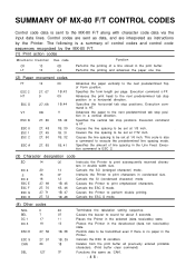
... Terminates the tabulation setting sequence. Permits data to the next predetermined tab stop position in double width size. Deletes from the print buffer all previously entered printable characters. (Print buffer clear command) Functions the same as instructions by the MX-80 F/T. (1) Print action codes M n e m o n i c D e c i m a l Hex. Execution command is VT. Causes the Printer to the next predetermined Top of line spacing in a horizontal direction. Instructs the Printer to be...
... Terminates the tabulation setting sequence. Permits data to the next predetermined tab stop position in double width size. Deletes from the print buffer all previously entered printable characters. (Print buffer clear command) Functions the same as instructions by the MX-80 F/T. (1) Print action codes M n e m o n i c D e c i m a l Hex. Execution command is VT. Causes the Printer to the next predetermined Top of line spacing in a horizontal direction. Instructs the Printer to be...


