Technical Brief (Impact Printers)
Page 4
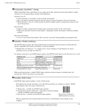
...tear-off Can be automatic or activated by pressing a button on pre-printed forms. LL L Versatility-Flexible interfacing Most EPSON impact printers offer both standard bidirectional parallel and serial interfaces which help you to add: Interface card 32KB Serial Serial Coax Twinax Multiprotocol...and Windows 98 drivers guarantees ease of use right out of built-in 2-point increments, available on EPSON 24-pin impact printers Barcode fonts-available on most paper paths, by a button on your computer. EPSON Sales Training EPSON is a registered trademark of Seiko Epson Corporation. 1/...
...tear-off Can be automatic or activated by pressing a button on pre-printed forms. LL L Versatility-Flexible interfacing Most EPSON impact printers offer both standard bidirectional parallel and serial interfaces which help you to add: Interface card 32KB Serial Serial Coax Twinax Multiprotocol...and Windows 98 drivers guarantees ease of use right out of built-in 2-point increments, available on EPSON 24-pin impact printers Barcode fonts-available on most paper paths, by a button on your computer. EPSON Sales Training EPSON is a registered trademark of Seiko Epson Corporation. 1/...

Product Information Guide
Page 6
...Printers LQ - 850/950/1050 DOT - Setting up the number of the page, ready for tractor paper. Sheet Loading When loading single sheets, make sure that the paper lever is usually done through the software, send a form feed command at the end of printer installed on position. To control it any Epson 24-pin driver... will be compatible. (Preferably, choose the LQ-800/1000.) DIP Switch Settings The default settings will usually work for using single sheets and for most applications, but they should be loaded manually or via the auto load button. MATRIX PRINTER ...
...Printers LQ - 850/950/1050 DOT - Setting up the number of the page, ready for tractor paper. Sheet Loading When loading single sheets, make sure that the paper lever is usually done through the software, send a form feed command at the end of printer installed on position. To control it any Epson 24-pin driver... will be compatible. (Preferably, choose the LQ-800/1000.) DIP Switch Settings The default settings will usually work for using single sheets and for most applications, but they should be loaded manually or via the auto load button. MATRIX PRINTER ...
Product Support Bulletin(s)
Page 15
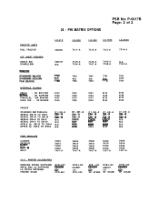
STAND DCB-LQ2 C842001 LQ1 KP - LQ2 ZYO' KP - STAND DCB-LQ2 i?iF1 KP - PIN MATRIX OPTIONS PSB No: P-0017B Page: 2 of 2 LQ-510 C800061 LQ-850 7311-A LQ-950 LQ-1050 LQ-2550 7313-A 7312-A 7314-A C806121 N/A 7339-A 7346-A 7345-A 7347-A 7340-A 7348-A N/A 7343-A INTERFACE BOARDS SERIAL - ...8239 zi 8239 C1-9E-A =I; STAND TRACTOR UNITS PULL TRACTOR CUT SHEET FEEDERS SINGLE BIN DOUBLE BIN 24 - PRINTER ACCESSORIES WINDOWS DRIVER SOFTWARE APPLE MAC LQ SOFTWARE LQ PATCH SOFWARE PRINTER STAND DCB-LQ2 El= CPD-552 DCB-LQ2 C842001 LQ1 CPD-552 DCB - N/A N/A N/A N/A FONT ...
STAND DCB-LQ2 C842001 LQ1 KP - LQ2 ZYO' KP - STAND DCB-LQ2 i?iF1 KP - PIN MATRIX OPTIONS PSB No: P-0017B Page: 2 of 2 LQ-510 C800061 LQ-850 7311-A LQ-950 LQ-1050 LQ-2550 7313-A 7312-A 7314-A C806121 N/A 7339-A 7346-A 7345-A 7347-A 7340-A 7348-A N/A 7343-A INTERFACE BOARDS SERIAL - ...8239 zi 8239 C1-9E-A =I; STAND TRACTOR UNITS PULL TRACTOR CUT SHEET FEEDERS SINGLE BIN DOUBLE BIN 24 - PRINTER ACCESSORIES WINDOWS DRIVER SOFTWARE APPLE MAC LQ SOFTWARE LQ PATCH SOFWARE PRINTER STAND DCB-LQ2 El= CPD-552 DCB-LQ2 C842001 LQ1 CPD-552 DCB - N/A N/A N/A N/A FONT ...
Technical Manual
Page 10
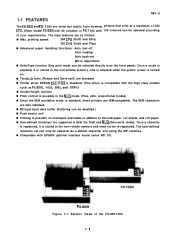
... is standard, these printers are IBM-compatible. q Printer driver EPSON ESC/P-83 is standard. (This driver is compatible with the high class models such as a default character set) using the DIP switches. REV.-A 1.1 FEATURES The FX-850 and FX-1 050 are serial dot matrix 9-pin terminal printers that print at a maximum of the FX-850/1050 1-1 Either model FX...
... is standard, these printers are IBM-compatible. q Printer driver EPSON ESC/P-83 is standard. (This driver is compatible with the high class models such as a default character set) using the DIP switches. REV.-A 1.1 FEATURES The FX-850 and FX-1 050 are serial dot matrix 9-pin terminal printers that print at a maximum of the FX-850/1050 1-1 Either model FX...

Technical Manual
Page 36
...printhead are also included on the PEGX board are: Universal IC q STK6722HZ (IC2A Carriage Motor Driver q NJM2355 (lCIA Switching Regulator IC Gate Array q E05A15HA (IC3A Paper Feed and Carriage Motors controller, and Printhead driver q E05A16GA (IC7A Host computer interface Memory IC q EP-ROM (IC4A Program ROM, 256... Other main ICS on this board. Since the complicated logic circuit section is the main board, and interfaces the printer to the host computer, controls the printer mechanism and control panel, and supplies DC voltage. REV.-A 1.11.2 PEGX Board (Main Board) The PEGX board...
...printhead are also included on the PEGX board are: Universal IC q STK6722HZ (IC2A Carriage Motor Driver q NJM2355 (lCIA Switching Regulator IC Gate Array q E05A15HA (IC3A Paper Feed and Carriage Motors controller, and Printhead driver q E05A16GA (IC7A Host computer interface Memory IC q EP-ROM (IC4A Program ROM, 256... Other main ICS on this board. Since the complicated logic circuit section is the main board, and interfaces the printer to the host computer, controls the printer mechanism and control panel, and supplies DC voltage. REV.-A 1.11.2 PEGX Board (Main Board) The PEGX board...

Technical Manual
Page 89
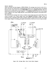
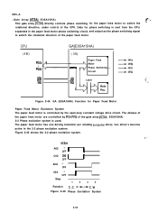
... Motor Excitation System The carriage motor is controlled by CRA - Because the carriage motor has one driving transistor per winding (unipolar drive), two drivers become active in the 2-2 phase excitation system and one and two drivers become active alternately in the 1-2 phase excitation system. Figure 2-37 shows the carriage motor drive sequences.
... Motor Excitation System The carriage motor is controlled by CRA - Because the carriage motor has one driving transistor per winding (unipolar drive), two drivers become active in the 2-2 phase excitation system and one and two drivers become active alternately in the 1-2 phase excitation system. Figure 2-37 shows the carriage motor drive sequences.
Technical Manual
Page 91
...motor supply voltages VCAB and VCCD are turned off, the surge voltage (e = - These phase drivers are switched directory by the corresponding phase driver A to D. Chopper control is absorbed. L X diidt) generated from ports CRA to each coil... Voltoge Absorber w ~ .- ,1 . - - '3 - - - 2 - + From E05A15HA A04 Col A B From E05A15HA ~ B04 Vcco ) Phase A Driver Phose B Driver Phase C Driver Phase D Driver -1 r I 1.-------%-LET', I Polof E05A16GA I Vref +5V h From Reference Voltage ( Generotlon Circuit ) Figure 2-38. Carriage Motor Drive Circuit Block Diagram 2-47...
...motor supply voltages VCAB and VCCD are turned off, the surge voltage (e = - These phase drivers are switched directory by the corresponding phase driver A to D. Chopper control is absorbed. L X diidt) generated from ports CRA to each coil... Voltoge Absorber w ~ .- ,1 . - - '3 - - - 2 - + From E05A15HA A04 Col A B From E05A15HA ~ B04 Vcco ) Phase A Driver Phose B Driver Phase C Driver Phase D Driver -1 r I 1.-------%-LET', I Polof E05A16GA I Vref +5V h From Reference Voltage ( Generotlon Circuit ) Figure 2-38. Carriage Motor Drive Circuit Block Diagram 2-47...
Technical Manual
Page 98
... feed motor are controlled by the open-loop constant voltage drive circuit. The paper feed motor has one driving transistor per winding (unipolar drive), two driver's become active in the paper feed motor phase switching circuit, and output as the phase switching signal to switch the rotational direction, under control of...
... feed motor are controlled by the open-loop constant voltage drive circuit. The paper feed motor has one driving transistor per winding (unipolar drive), two driver's become active in the paper feed motor phase switching circuit, and output as the phase switching signal to switch the rotational direction, under control of...

Technical Manual
Page 106
...I I 1 I I I I , I From : m; I1 J Figure 2-52. REV.-A & Half-dot Protection Circuit The half-dot protection circuit is located in the gate array (E05AI 5HA). It ignores any drive pulses received after the dot wires of the printhead (see Figure 2-3) have been driven for the maximum allowable drive time, to prevent the ...printhead from being damaged. I I I 1 1 I I I I Buffer N v I +- ~J Holf dot Protect Ion Circuit 9uffer It A ~Dd III To Prlntheod Driver...
...I I 1 I I I I , I From : m; I1 J Figure 2-52. REV.-A & Half-dot Protection Circuit The half-dot protection circuit is located in the gate array (E05AI 5HA). It ignores any drive pulses received after the dot wires of the printhead (see Figure 2-3) have been driven for the maximum allowable drive time, to prevent the ...printhead from being damaged. I I I 1 1 I I I I Buffer N v I +- ~J Holf dot Protect Ion Circuit 9uffer It A ~Dd III To Prlntheod Driver...
Technical Manual
Page 110
... -8 4.2.3 Push Tractor Unit Removal 4. -8 4.2.4 Circuit Board Removal 4-9 4.2.4.1 PEGX Board Removal 4-9 4.2.4.2 PEBFIL-11 Board Removal 4-11 4.2.5 Printer Mechanism Disassembly 4-12 4.2.5.1 Printer Mechanism Removal 4-13 4.2.5.2 Printhead Removal 4-14 4.2.5.3 FPC (Flexible Printed Cable) Removal ......... 4-15 4.2.5.4 Carriage Motor Removal 4-16 4.2.5.5 Timing Belt...23 4.2.5.11 Paper Release Lever Removal 4-24 4.2.5.12 Main and Base Frame Removal 4-25 4.2.5.13 Ribbon Driver Unit Removal 4-28 4.2.5.14 Carriage Removal 4-29 4.2.5.15 Paper Guide Plate Removal 4-31 4.2.5.16 Paper Feed...
... -8 4.2.3 Push Tractor Unit Removal 4. -8 4.2.4 Circuit Board Removal 4-9 4.2.4.1 PEGX Board Removal 4-9 4.2.4.2 PEBFIL-11 Board Removal 4-11 4.2.5 Printer Mechanism Disassembly 4-12 4.2.5.1 Printer Mechanism Removal 4-13 4.2.5.2 Printhead Removal 4-14 4.2.5.3 FPC (Flexible Printed Cable) Removal ......... 4-15 4.2.5.4 Carriage Motor Removal 4-16 4.2.5.5 Timing Belt...23 4.2.5.11 Paper Release Lever Removal 4-24 4.2.5.12 Main and Base Frame Removal 4-25 4.2.5.13 Ribbon Driver Unit Removal 4-28 4.2.5.14 Carriage Removal 4-29 4.2.5.15 Paper Guide Plate Removal 4-31 4.2.5.16 Paper Feed...
Technical Manual
Page 112
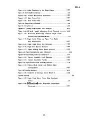
REV.-A Figure 4-34. Printer Mechanism Separation 4-26 Figure 4-37. Base Frame Unit 4. .-27 Figure 4-39. LS and Parallel Adjustment Bush Removal 4-30 Figure 4-43. Tractor Assembly Phases 4. -35 Figure 4-... Springs 4-31 Figure 4-44. Paper Guide Plate and Paper Feed Roller Unit Relationship 4. .-31 Figure 4-45. Paper Tension Roller Assembly Removal 4-36 Figure 4-53. Ribbon Driver Unit Removal 4-28 Figure 4-4o. Paper Holding Roller Shaft Removal 4-33 Figure 4-48. Tractor Assembly (Left) Removal 4-35 Figure 4-51. Eccentric of Carriage Guide Shaft...
REV.-A Figure 4-34. Printer Mechanism Separation 4-26 Figure 4-37. Base Frame Unit 4. .-27 Figure 4-39. LS and Parallel Adjustment Bush Removal 4-30 Figure 4-43. Tractor Assembly Phases 4. -35 Figure 4-... Springs 4-31 Figure 4-44. Paper Guide Plate and Paper Feed Roller Unit Relationship 4. .-31 Figure 4-45. Paper Tension Roller Assembly Removal 4-36 Figure 4-53. Ribbon Driver Unit Removal 4-28 Figure 4-4o. Paper Holding Roller Shaft Removal 4-33 Figure 4-48. Tractor Assembly (Left) Removal 4-35 Figure 4-51. Eccentric of Carriage Guide Shaft...
Technical Manual
Page 114
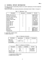
Maintenance Tools Description Philips screw driver #2 Box driver (7 mm across) Thickness gauge (0.50 mm) Round nose pliers Diagonal cutting nipper Tweezers E-ring holder #2.5 E-ring holder #3 E-ring holder #4... B740400100 B740500 100 B64 1000100 B740900400 B740800500 B740800600 B740800700 o B740200 100 0 B74 1400200 0 B74 1400100 o B74 1600100 o: Commercially available product E: EPSON exclusive tool Description Multi meter Oscilloscope Logic analizer Table 4-2. 4.1 GENERAL REPAIR INFORMATION REV.-A This chapter describes the disassembly procedures to be used for replacing...
Maintenance Tools Description Philips screw driver #2 Box driver (7 mm across) Thickness gauge (0.50 mm) Round nose pliers Diagonal cutting nipper Tweezers E-ring holder #2.5 E-ring holder #3 E-ring holder #4... B740400100 B740500 100 B64 1000100 B740900400 B740800500 B740800600 B740800700 o B740200 100 0 B74 1400200 0 B74 1400100 o B74 1600100 o: Commercially available product E: EPSON exclusive tool Description Multi meter Oscilloscope Logic analizer Table 4-2. 4.1 GENERAL REPAIR INFORMATION REV.-A This chapter describes the disassembly procedures to be used for replacing...
Technical Manual
Page 140
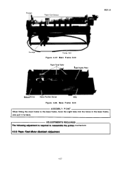
TADJUSTMENTSREQU'RED The following adjustment is required to the base frame, hook the eight tabs into the holes in the base frame, and pull it forward. Base Frame Unit ASSEMBLY POINT When fitting the main frame to reassemble the printer mechanism: 4.3.2 Paper Feed Motor Backlash Adjustment 4-27 REV.-A \~ Carriage Timing Belt Figure 4-37. Main Frame Unit Paper Feed Roller A..., PaDer Guide Plate Ribbo~ Driver Home Position Senser FPC Figure 4-38.
TADJUSTMENTSREQU'RED The following adjustment is required to the base frame, hook the eight tabs into the holes in the base frame, and pull it forward. Base Frame Unit ASSEMBLY POINT When fitting the main frame to reassemble the printer mechanism: 4.3.2 Paper Feed Motor Backlash Adjustment 4-27 REV.-A \~ Carriage Timing Belt Figure 4-37. Main Frame Unit Paper Feed Roller A..., PaDer Guide Plate Ribbo~ Driver Home Position Senser FPC Figure 4-38.
Technical Manual
Page 141
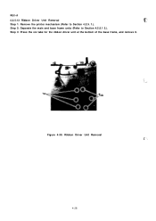
Ribbon Driver Unit Removal .c*- ', 4-28 REV.-A 4.2.5.13 Ribbon Driver Unit Removal g$..!'.:, Step 1: Remove the printer mechanism (Refer to Section 4.2.5.1 2.). Step 3: Press the six tabs for the ribbon driver unit at the bottom of the base frame, and remove it. Tab Tab Figure 4-39. Step 2: Separate the main and base frame units (Refer to Section 4.2.5. 1.).
Ribbon Driver Unit Removal .c*- ', 4-28 REV.-A 4.2.5.13 Ribbon Driver Unit Removal g$..!'.:, Step 1: Remove the printer mechanism (Refer to Section 4.2.5.1 2.). Step 3: Press the six tabs for the ribbon driver unit at the bottom of the base frame, and remove it. Tab Tab Figure 4-39. Step 2: Separate the main and base frame units (Refer to Section 4.2.5. 1.).
Technical Manual
Page 150
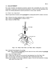
Step 7: Turn the larger countersink of the parts described in this printer. REV.-A 4.3 A D J U S T M E N T This section describes the adjustment procedures required when reassembling this section, the following adjustments should be performed to ensure proper ... the head adjustment lever (See Figure 4-50). Step 8: Insert the blade of a screw driver (a diameter is performed during maintenance or repaires of carriage guide shaft B upward (See Figure 4-55). Step 1: Remove the printer mechanism (Refer to Section 4.2.5. NOTE: When reinstalling the printhead, lock the head lock levers ...
Step 7: Turn the larger countersink of the parts described in this printer. REV.-A 4.3 A D J U S T M E N T This section describes the adjustment procedures required when reassembling this section, the following adjustments should be performed to ensure proper ... the head adjustment lever (See Figure 4-50). Step 8: Insert the blade of a screw driver (a diameter is performed during maintenance or repaires of carriage guide shaft B upward (See Figure 4-55). Step 1: Remove the printer mechanism (Refer to Section 4.2.5. NOTE: When reinstalling the printhead, lock the head lock levers ...
Technical Manual
Page 185
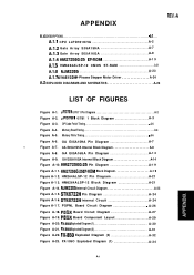
... A-1 9 Figure A-1 2. A.1.l CPU LLPD781OHG A. . -2 A.1.2 Gate Array E05A15HA A. -7 A.1.3 Gate Array E05A16GA A. -9 A.1.4 HM27256G-25 EP-ROM A. -1 9 A.1.5 HM6264ALSP-12 CMOS ST-RAM A-21 A.1.6 NJM2355 A. . .-23 A.1.7 STK6722H 4-Phases Stepper Motor Driver A-24 A.2 EXPLODED DIAGRAMS AND SCHEMATICS A-26 LIST OF FIGURES Figure A-1. wPD781 0/781 1 Pin Diagram A-2 Figure A-2. REV.-A APPENDIX A.1 IC DESCRIPTIONS A.-1. . . . .
... A-1 9 Figure A-1 2. A.1.l CPU LLPD781OHG A. . -2 A.1.2 Gate Array E05A15HA A. -7 A.1.3 Gate Array E05A16GA A. -9 A.1.4 HM27256G-25 EP-ROM A. -1 9 A.1.5 HM6264ALSP-12 CMOS ST-RAM A-21 A.1.6 NJM2355 A. . .-23 A.1.7 STK6722H 4-Phases Stepper Motor Driver A-24 A.2 EXPLODED DIAGRAMS AND SCHEMATICS A-26 LIST OF FIGURES Figure A-1. wPD781 0/781 1 Pin Diagram A-2 Figure A-2. REV.-A APPENDIX A.1 IC DESCRIPTIONS A.-1. . . . .
Technical Manual
Page 192
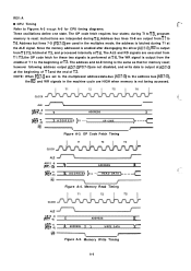
... x A D D R E S S }- - - - < OP CODE / x >---c Figure A-3. Memory Read Timing CLOCK AB15 -8 (PF7 -0) AD7 -0 (PD7 -0) x ADDRESS x x x ADDRESS WRITE DATA Figure A-5. Since the memory addressed is enabled after disengaging the driver (AD7-0), ~ is the same as that for memory read ; the OP code fetch for CPU timing diagrams. Three oscillations define one state. c Figure A-4. The ALE...
... x A D D R E S S }- - - - < OP CODE / x >---c Figure A-3. Memory Read Timing CLOCK AB15 -8 (PF7 -0) AD7 -0 (PD7 -0) x ADDRESS x x x ADDRESS WRITE DATA Figure A-5. Since the memory addressed is enabled after disengaging the driver (AD7-0), ~ is the same as that for memory read ; the OP code fetch for CPU timing diagrams. Three oscillations define one state. c Figure A-4. The ALE...

Technical Manual
Page 210
D1O - 011 *I7 082 *I 1 2 3456 18 Figure A-1 5. d -- - I I * 07 DO ~------ --= ------- 1; 1, n: t "4 ; 8: 1------- _l L------ - -~ .Jw_- ,, ~, ,, ,/ , L ----- STK6722H Pin Diagram I* , Q,> 9Z t4 Is m I I Figure A-1 6. II I I nls 1 4~ :cQJ II- mm f. ... . . STK6722H Internal Circuit A-24 REV.-A A.1.7 STK6722H 4-Phases Stepper Motor Driver ./T% The STK6722H is an uni-polar constant current chopper driver IC for the four phases stepper motor.
D1O - 011 *I7 082 *I 1 2 3456 18 Figure A-1 5. d -- - I I * 07 DO ~------ --= ------- 1; 1, n: t "4 ; 8: 1------- _l L------ - -~ .Jw_- ,, ~, ,, ,/ , L ----- STK6722H Pin Diagram I* , Q,> 9Z t4 Is m I I Figure A-1 6. II I I nls 1 4~ :cQJ II- mm f. ... . . STK6722H Internal Circuit A-24 REV.-A A.1.7 STK6722H 4-Phases Stepper Motor Driver ./T% The STK6722H is an uni-polar constant current chopper driver IC for the four phases stepper motor.


