User Manual
Page 32
... the LQ-2070 as the default printer. Select LQ-2070 ESC/P 2 as the Printer Model and click Continue. Setting Up the Printer 1-15 Make sure Windows is running Windows 95, see page 1-16 for Windows 3.1: 1. If you are running . 2. The LQ-2070 printer driver is now installed on your computer). 3. Installing the Printer Driver The EPSON printer driver is software that came with your printer includes the driver...
... the LQ-2070 as the default printer. Select LQ-2070 ESC/P 2 as the Printer Model and click Continue. Setting Up the Printer 1-15 Make sure Windows is running Windows 95, see page 1-16 for Windows 3.1: 1. If you are running . 2. The LQ-2070 printer driver is now installed on your computer). 3. Installing the Printer Driver The EPSON printer driver is software that came with your printer includes the driver...
User Manual
Page 38
... changes from the list below. You can use EPSON Remote! If the LQ-2070 is not included in the list, contact your computer instead of printers to see if there is an updated driver available or select the first printer available from your software manufacturer to install the printer driver. For DOS program users Most DOS software programs...
... changes from the list below. You can use EPSON Remote! If the LQ-2070 is not included in the list, contact your computer instead of printers to see if there is an updated driver available or select the first printer available from your software manufacturer to install the printer driver. For DOS program users Most DOS software programs...
Service Manual
Page 45
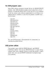
... 1-36 Rev.A Head Driva TRANSISTOR IC 5 PS RAM ICI 1,14 PF Motor Driver TEA3718SDP 1 1 ~n D .H / \ IC12 CR Motor Driver SLA7024M IC 8 'CN2 for the main board and printer mechanism. w 'CIkDE,D l I I F EEPROM Figure 1-13 C186 MAIN Board... Assembly 1.6.2 C166 PSB/PSE Board Assembly These boardshave two AC input voltage ratings: 120VAC (C166PSB) and230VAC (C166PSE). F1 Q1 Fuse Switching FET I 1. /- C!!!!!o0 ; Product Description LQ-2070...
... 1-36 Rev.A Head Driva TRANSISTOR IC 5 PS RAM ICI 1,14 PF Motor Driver TEA3718SDP 1 1 ~n D .H / \ IC12 CR Motor Driver SLA7024M IC 8 'CN2 for the main board and printer mechanism. w 'CIkDE,D l I I F EEPROM Figure 1-13 C186 MAIN Board... Assembly 1.6.2 C166 PSB/PSE Board Assembly These boardshave two AC input voltage ratings: 120VAC (C166PSB) and230VAC (C166PSE). F1 Q1 Fuse Switching FET I 1. /- C!!!!!o0 ; Product Description LQ-2070...
Service Manual
Page 49
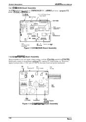
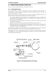
...stops energizing the coil, the magnetic force from the control circuit to the printhead driver circuit, is connected to the core, rushes toward the core, and the dot wire, which is converted to the proper printhead driving voltage, which causes the wire... Core Head Driving Coil Actuating Spring Platen Figure 2-1 Printhead Operation Principles Rev.A 2-1 LQ-2070 Service Manual Operating Principles 2.1 PRINTER MECHANISM OPERATION This section describes the printer mechanism and explains how it prints a dot. 4. The printhead is composed of 1.65 KHz for beep codes. A drive ...
...stops energizing the coil, the magnetic force from the control circuit to the printhead driver circuit, is connected to the core, rushes toward the core, and the dot wire, which is converted to the proper printhead driving voltage, which causes the wire... Core Head Driving Coil Actuating Spring Platen Figure 2-1 Printhead Operation Principles Rev.A 2-1 LQ-2070 Service Manual Operating Principles 2.1 PRINTER MECHANISM OPERATION This section describes the printer mechanism and explains how it prints a dot. 4. The printhead is composed of 1.65 KHz for beep codes. A drive ...

Service Manual
Page 65
...(120 V) or C166 PSE (230 V) power supply. Rev.A 2-17 LQ-2070 Service Manual Operating Principles 2.2 POWER SUPPLY OPERATION The printer can be powered by either of the power supply circuitry. Control Panel LEDs Printhead Driver Primary Circuit Secondary Circuit +5V Switching Regurator +5V Constant Voltage Control Circuit +...secondary smoothing circuit produces a stepped down to the gate port for a difference in the figure above, when AC power enters the printer from the 35 VDC line. These boards are the same as the FX-2170. The +5 VDC voltage is generated by the various...
...(120 V) or C166 PSE (230 V) power supply. Rev.A 2-17 LQ-2070 Service Manual Operating Principles 2.2 POWER SUPPLY OPERATION The printer can be powered by either of the power supply circuitry. Control Panel LEDs Printhead Driver Primary Circuit Secondary Circuit +5V Switching Regurator +5V Constant Voltage Control Circuit +...secondary smoothing circuit produces a stepped down to the gate port for a difference in the figure above, when AC power enters the printer from the 35 VDC line. These boards are the same as the FX-2170. The +5 VDC voltage is generated by the various...
Service Manual
Page 71
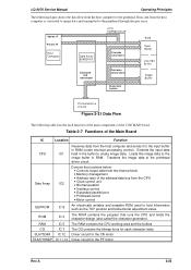
Loads this image data to the printhead driver circuit. RAM IC 5 The RAM contains the CPU working area and the buffers CG IC 7 The CG contains the bitmap fonts for the PF motor ... the input buffer in the buffer to the printhead through the gate array. LQ-2070 Service Manual Operating Principles The following table lists the each character table SLA7024M IC 12 Driver circuit for the CR motor TEA3718SDP IC 11,14 Driver circuit for each function of the main components of the C186 MAIN board.
Loads this image data to the printhead driver circuit. RAM IC 5 The RAM contains the CPU working area and the buffers CG IC 7 The CG contains the bitmap fonts for the PF motor ... the input buffer in the buffer to the printhead through the gate array. LQ-2070 Service Manual Operating Principles The following table lists the each character table SLA7024M IC 12 Driver circuit for the CR motor TEA3718SDP IC 11,14 Driver circuit for each function of the main components of the C186 MAIN board.
Service Manual
Page 72
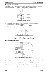
...then 100 ms passes. (v) 5 4 3 2 1 Power On 100ms RESET VOUT (RESET) 100ms RESET VCC (+5V line) Figure 2-33 Reset Signal Output Timing 2.3.3 Printhead Driver Circuit Print Head +35V +35V + C9 HT MP Printhead Drive Transistor Q1~Q12, Q13~24 R49 Printhead Drive Signal 69 76~89 91~99 ~ ~ Gate...the printhead driver pulse width. Port 74 monitors the +35 V line between R50 and R51 to the gate array via CPU port 15. If the temperature exceeds 95° C (213° F) , printing is output. Port 73 monitors the printhead temperature to CPU port 78. Operation Principles LQ-2070 Servcie ...
...then 100 ms passes. (v) 5 4 3 2 1 Power On 100ms RESET VOUT (RESET) 100ms RESET VCC (+5V line) Figure 2-33 Reset Signal Output Timing 2.3.3 Printhead Driver Circuit Print Head +35V +35V + C9 HT MP Printhead Drive Transistor Q1~Q12, Q13~24 R49 Printhead Drive Signal 69 76~89 91~99 ~ ~ Gate...the printhead driver pulse width. Port 74 monitors the +35 V line between R50 and R51 to the gate array via CPU port 15. If the temperature exceeds 95° C (213° F) , printing is output. Port 73 monitors the printhead temperature to CPU port 78. Operation Principles LQ-2070 Servcie ...
Service Manual
Page 73
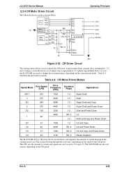
... coil current, depending on the speed of current flowing in the carriage motor coil. Rev.A 2-25 LQ-2070 Service Manual 2.3.4 CR Motor Driver Circuit The CR motor driver circuit is equivalent to a 1-2 phase step doubled. Table 2-8 CR Motor Driver Modes Speed Mode Print Speed (CPS) Drive Frequency (PPS) Excitation Phase Applications 36/11 300 7200...
... coil current, depending on the speed of current flowing in the carriage motor coil. Rev.A 2-25 LQ-2070 Service Manual 2.3.4 CR Motor Driver Circuit The CR motor driver circuit is equivalent to a 1-2 phase step doubled. Table 2-8 CR Motor Driver Modes Speed Mode Print Speed (CPS) Drive Frequency (PPS) Excitation Phase Applications 36/11 300 7200...
Service Manual
Page 74
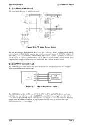
... via ports 7 (PPG3), 8 (PPG2), 9 (PPG1), and 10 (PPG0), converts the data to TEA3718SDP form, and then sends that stores information even if the printer power is off. Port 70 is the chip select line, and port 71 is the data input line used to save the information to 4.75...necessary data to the EEPROM before the +5 V line drops to the EEPROM, and port 12 is the clock timing line. Operation Principles LQ-2070 Servcie Manual 2.3.5 PF Motor Driver Circuit The figure below shows the EEPROM control circuit. These controlled drive currents are output via ports 32 (PHASEA) and ports 129 (...
... via ports 7 (PPG3), 8 (PPG2), 9 (PPG1), and 10 (PPG0), converts the data to TEA3718SDP form, and then sends that stores information even if the printer power is off. Port 70 is the chip select line, and port 71 is the data input line used to save the information to 4.75...necessary data to the EEPROM before the +5 V line drops to the EEPROM, and port 12 is the clock timing line. Operation Principles LQ-2070 Servcie Manual 2.3.5 PF Motor Driver Circuit The figure below shows the EEPROM control circuit. These controlled drive currents are output via ports 32 (PHASEA) and ports 129 (...

Service Manual
Page 75
...the photo diode rays are cut off by the sensor plate, which is included in this printer. Rev.A 2-27 The rear PE sensor detects that was measured during the power on the...momentary switches. The PW sensor, used in the rear PE sensor. Additionally, as mentioned on sequence. LQ-2070 Service Manual Operating Principles 2.3.7 Sensor Circuits The CPU detects conditions of the following sensors: home position (HP...Release Sensor 2 Release Sensor 1 Two types of the head driver signal. Release sensors 1 and 2, the PG sensors, and the front PE sensor are photo diode switches.
...the photo diode rays are cut off by the sensor plate, which is included in this printer. Rev.A 2-27 The rear PE sensor detects that was measured during the power on the...momentary switches. The PW sensor, used in the rear PE sensor. Additionally, as mentioned on sequence. LQ-2070 Service Manual Operating Principles 2.3.7 Sensor Circuits The CPU detects conditions of the following sensors: home position (HP...Release Sensor 2 Release Sensor 1 Two types of the head driver signal. Release sensors 1 and 2, the PG sensors, and the front PE sensor are photo diode switches.
Service Manual
Page 131
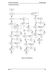
LQ-2070 Service Manual 4. Replace any wires in the YES printhead broken? Are any bad parts. Reset the printer. EENNDD Dose END Replace the the printer work OK with computer. NO Problem with another computer? Date received from the host is...YES Is the NO FFC connected correctly? EENNDD Is the YES problem corrected ? Is the problem corrected ? Are the correct printer drivers installed ? EEENNNDDD NO Is the YES problem corrected ? FFC. Connect the cable correctly. EENNDD YES Replace the C186 MAIN baord...
LQ-2070 Service Manual 4. Replace any wires in the YES printhead broken? Are any bad parts. Reset the printer. EENNDD Dose END Replace the the printer work OK with computer. NO Problem with another computer? Date received from the host is...YES Is the NO FFC connected correctly? EENNDD Is the YES problem corrected ? Is the problem corrected ? Are the correct printer drivers installed ? EEENNNDDD NO Is the YES problem corrected ? FFC. Connect the cable correctly. EENNDD YES Replace the C186 MAIN baord...


