User Manual
Page 32
... menu, choose Run. 4. The EPSON printer driver disk that helps you take full advantage of your computer. For Microsoft Windows Users Before you need to change the default printer or port assignment, use the LQ-2070 as the Printer Model and click Continue. Setting Up the Printer 1-15 Select LQ-2070 ESC/P 2 as the default printer. The LQ-2070 printer driver is installed automatically. 6. Install...
... menu, choose Run. 4. The EPSON printer driver disk that helps you take full advantage of your computer. For Microsoft Windows Users Before you need to change the default printer or port assignment, use the LQ-2070 as the Printer Model and click Continue. Setting Up the Printer 1-15 Select LQ-2070 ESC/P 2 as the default printer. The LQ-2070 printer driver is installed automatically. 6. Install...
User Manual
Page 38
... LQ-2500 LQ-800/1000 LQ-1500 See your computer instead of printers to select from the list below. If the LQ-2070 is not included in the list, contact your printout. and EPSON Calibration utilities. Also, DOS programs require you can use EPSON Calibration to properly align your software manufacturer to see if there is an updated driver...
... LQ-2500 LQ-800/1000 LQ-1500 See your computer instead of printers to select from the list below. If the LQ-2070 is not included in the list, contact your printout. and EPSON Calibration utilities. Also, DOS programs require you can use EPSON Calibration to properly align your software manufacturer to see if there is an updated driver...
Service Manual
Page 45
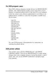
...Board Assembly 1-36 Rev.A Head Driva TRANSISTOR IC 5 PS RAM ICI 1,14 PF Motor Driver TEA3718SDP 1 1 ~n D .H / \ IC12 CR Motor Driver SLA7024M IC 8 'CN2 for the main board and printer mechanism. F1 Q1 Fuse Switching FET I F EEPROM Figure 1-13 C186 MAIN Board Assembly..., a program/CG ROM, a PS-IWM, an EEPROM, etc. w 'CIkDE,D l I I o Pcl Photo Coupler / / / / 1/ .- - Product Description LQ-2070 Service Manual 1.6.1 C186 MAIN Board Assembly The C186 MAIN board consists of a transformer, switcking FET, regulator IC, diode bridge, etc. C!!!!!o0 ;
...Board Assembly 1-36 Rev.A Head Driva TRANSISTOR IC 5 PS RAM ICI 1,14 PF Motor Driver TEA3718SDP 1 1 ~n D .H / \ IC12 CR Motor Driver SLA7024M IC 8 'CN2 for the main board and printer mechanism. F1 Q1 Fuse Switching FET I F EEPROM Figure 1-13 C186 MAIN Board Assembly..., a program/CG ROM, a PS-IWM, an EEPROM, etc. w 'CIkDE,D l I I o Pcl Photo Coupler / / / / 1/ .- - Product Description LQ-2070 Service Manual 1.6.1 C186 MAIN Board Assembly The C186 MAIN board consists of a transformer, switcking FET, regulator IC, diode bridge, etc. C!!!!!o0 ;
Service Manual
Page 49
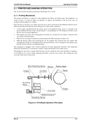
...driver circuit, is equipped with spring action. A drive signal, transmitted from the iron core vanishes. The mechanism is converted to its own drive coil, which causes the wire to move all the dot wires back and forth at a frequency of the printhead to become magnetized. 2. LQ-2070 Service Manual Operating Principles 2.1 PRINTER... MECHANISM OPERATION This section describes the printer mechanism and explains ...
...driver circuit, is equipped with spring action. A drive signal, transmitted from the iron core vanishes. The mechanism is converted to its own drive coil, which causes the wire to move all the dot wires back and forth at a frequency of the printhead to become magnetized. 2. LQ-2070 Service Manual Operating Principles 2.1 PRINTER... MECHANISM OPERATION This section describes the printer mechanism and explains ...

Service Manual
Page 65
... by feeding the +35 VDC voltage through resistors R18 and R31, and then the switching circuit operates. Control Panel LEDs Printhead Driver Primary Circuit Secondary Circuit +5V Switching Regurator +5V Constant Voltage Control Circuit +5V Over current Protection Circuit +5V DC Full Wave...stepped down +35 VDC voltage. Rev.A 2-17 The voltage is fed to drive the printer control circuits and drive mechanism. LQ-2070 Service Manual Operating Principles 2.2 POWER SUPPLY OPERATION The printer can be powered by the various control circuits and drive mechanisms. Table 2-6 lists the ...
... by feeding the +35 VDC voltage through resistors R18 and R31, and then the switching circuit operates. Control Panel LEDs Printhead Driver Primary Circuit Secondary Circuit +5V Switching Regurator +5V Constant Voltage Control Circuit +5V Over current Protection Circuit +5V DC Full Wave...stepped down +35 VDC voltage. Rev.A 2-17 The voltage is fed to drive the printer control circuits and drive mechanism. LQ-2070 Service Manual Operating Principles 2.2 POWER SUPPLY OPERATION The printer can be powered by the various control circuits and drive mechanisms. Table 2-6 lists the ...
Service Manual
Page 71
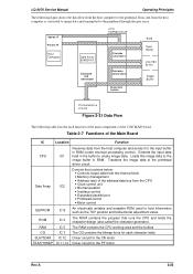
... the program that runs the CPU and holds the character design (also called the character generator). Loads this image data to the printhead driver circuit. Extends the input data IC1 held in RAM (under interrupt processing control). RAM IC 5 The RAM contains the CPU working area...contains the bitmap fonts for each function of the main components of the C186 MAIN board. LQ-2070 Service Manual Operating Principles The following table lists the each character table SLA7024M IC 12 Driver circuit for the CR motor TEA3718SDP IC 11,14 Driver circuit for the PF motor Rev.A 2-23
... the program that runs the CPU and holds the character design (also called the character generator). Loads this image data to the printhead driver circuit. Extends the input data IC1 held in RAM (under interrupt processing control). RAM IC 5 The RAM contains the CPU working area...contains the bitmap fonts for each function of the main components of the C186 MAIN board. LQ-2070 Service Manual Operating Principles The following table lists the each character table SLA7024M IC 12 Driver circuit for the CR motor TEA3718SDP IC 11,14 Driver circuit for the PF motor Rev.A 2-23
Service Manual
Page 72
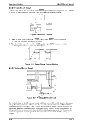
...monitored voltage, the CPU converts the voltage to a digital value and decides the printhead driver pulse width, and then transports the data to the gate array via CPU port 15. Operation Principles LQ-2070 Servcie Manual 2.3.2 System Reset Circuit Control circuits IC1 and IC2 are initialized when a ... ms passes. (v) 5 4 3 2 1 Power On 100ms RESET VOUT (RESET) 100ms RESET VCC (+5V line) Figure 2-33 Reset Signal Output Timing 2.3.3 Printhead Driver Circuit Print Head +35V +35V + C9 HT MP Printhead Drive Transistor Q1~Q12, Q13~24 R49 Printhead Drive Signal 69 76~89 91~99 ~ ~ Gate...
...monitored voltage, the CPU converts the voltage to a digital value and decides the printhead driver pulse width, and then transports the data to the gate array via CPU port 15. Operation Principles LQ-2070 Servcie Manual 2.3.2 System Reset Circuit Control circuits IC1 and IC2 are initialized when a ... ms passes. (v) 5 4 3 2 1 Power On 100ms RESET VOUT (RESET) 100ms RESET VCC (+5V line) Figure 2-33 Reset Signal Output Timing 2.3.3 Printhead Driver Circuit Print Head +35V +35V + C9 HT MP Printhead Drive Transistor Q1~Q12, Q13~24 R49 Printhead Drive Signal 69 76~89 91~99 ~ ~ Gate...
Service Manual
Page 73
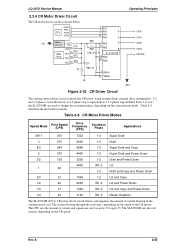
...Down 4400 W1-2 LQ 1 92 1-2 Draft and Copy and Power Down 2/3 61 1464 1-2 LQ and Copy 1/2 46 2200 W1-2 LQ and Power Down 1/3 31 1464 W1-2 LQ and Copy and Power Down 1/4 23 1100 W1-2 Raster Graphics The SLA7024M (IC12) CR motor driver circuit detects and regulates... the selected print mode. Rev.A 2-25 A 2-2 phase step is shown below. LQ-2070 Service Manual 2.3.4 CR Motor Driver Circuit The CR motor driver circuit is equivalent to a 1-2 phase step doubled. Table 2-8 describes the motor driver modes. CPU PG00 1 PG01 2 PG02 3 PG03 4 +5V Address Data Line R72...
...Down 4400 W1-2 LQ 1 92 1-2 Draft and Copy and Power Down 2/3 61 1464 1-2 LQ and Copy 1/2 46 2200 W1-2 LQ and Power Down 1/3 31 1464 W1-2 LQ and Copy and Power Down 1/4 23 1100 W1-2 Raster Graphics The SLA7024M (IC12) CR motor driver circuit detects and regulates... the selected print mode. Rev.A 2-25 A 2-2 phase step is shown below. LQ-2070 Service Manual 2.3.4 CR Motor Driver Circuit The CR motor driver circuit is equivalent to a 1-2 phase step doubled. Table 2-8 describes the motor driver modes. CPU PG00 1 PG01 2 PG02 3 PG03 4 +5V Address Data Line R72...
Service Manual
Page 74
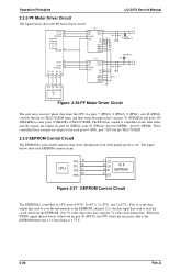
...controlled drive currents are output via ports 32 (PHASEA) and ports 129 (PHASEB) to TEA3718SDP form, and then sends that stores information even if the printer power is the data input line used to read the saved data from the CPU via ports 7 (PPG3), 8 (PPG2), 9 (PPG1), and 10... Control Circuit The EEPROM is detected on the Gate Array and the signals are output to 4.75 V. 2-26 Rev.A Operation Principles LQ-2070 Servcie Manual 2.3.5 PF Motor Driver Circuit The figure below shows the EEPROM control circuit. When the PWDN signal (power down) is non-volatile memory that phase data ...
...controlled drive currents are output via ports 32 (PHASEA) and ports 129 (PHASEB) to TEA3718SDP form, and then sends that stores information even if the printer power is the data input line used to read the saved data from the CPU via ports 7 (PPG3), 8 (PPG2), 9 (PPG1), and 10... Control Circuit The EEPROM is detected on the Gate Array and the signals are output to 4.75 V. 2-26 Rev.A Operation Principles LQ-2070 Servcie Manual 2.3.5 PF Motor Driver Circuit The figure below shows the EEPROM control circuit. When the PWDN signal (power down) is non-volatile memory that phase data ...

Service Manual
Page 75
...photo diode rays are cut off by the sensor plate, which is included in this printer. The rear PE sensor detects that was measured during the power on the page 2-24... paper loading positioning, detects the paper edge by the printhead. Additionally, as mentioned on sequence. LQ-2070 Service Manual Operating Principles 2.3.7 Sensor Circuits The CPU detects conditions of the following sensors: home position... Release Sensor 1 Two types of sensors are monitored to set the pulse length of the head driver signal. The HP sensor, rear PE sensor, and PW sensor are momentary switches. Rev.A ...
...photo diode rays are cut off by the sensor plate, which is included in this printer. The rear PE sensor detects that was measured during the power on the page 2-24... paper loading positioning, detects the paper edge by the printhead. Additionally, as mentioned on sequence. LQ-2070 Service Manual Operating Principles 2.3.7 Sensor Circuits The CPU detects conditions of the following sensors: home position... Release Sensor 1 Two types of sensors are monitored to set the pulse length of the head driver signal. The HP sensor, rear PE sensor, and PW sensor are momentary switches. Rev.A ...
Service Manual
Page 131
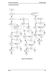
...5-6 Flowchart 4 Rev.A 5-9 YES Do all NO the dosts printed OK? Are the correct printer drivers installed ? YES Is the YES probelm corrected? EENNDD Is the YES problem corrected ? LQ-2070 Service Manual 4. YES Replace the printhead.. Is the problem corrected ? YES NO Is the ...YES problem corrected ? EENNDD Dose END Replace the the printer work OK with another computer? YES NO Replace the...
...5-6 Flowchart 4 Rev.A 5-9 YES Do all NO the dosts printed OK? Are the correct printer drivers installed ? YES Is the YES probelm corrected? EENNDD Is the YES problem corrected ? LQ-2070 Service Manual 4. YES Replace the printhead.. Is the problem corrected ? YES NO Is the ...YES problem corrected ? EENNDD Dose END Replace the the printer work OK with another computer? YES NO Replace the...


