Literature/Product Sheet
Page 1
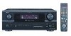
... a Multi Zone Output function and a Select function that is used to switch component video signals, features an extended bandwidth range up to component video signals and output to the monitor, this allows you enjoy the highest picture quality from S-Video to Composite • 3 Sets of Component Video Inputs The AVR-2805 is equipped with 3 sets of assignable, component video inputs and 1set of monitor outputs with 100 Watts per channel output power, while still providing 5 discrete amplifier channels to drive all speakers in all surround modes to support...
... a Multi Zone Output function and a Select function that is used to switch component video signals, features an extended bandwidth range up to component video signals and output to the monitor, this allows you enjoy the highest picture quality from S-Video to Composite • 3 Sets of Component Video Inputs The AVR-2805 is equipped with 3 sets of assignable, component video inputs and 1set of monitor outputs with 100 Watts per channel output power, while still providing 5 discrete amplifier channels to drive all speakers in all surround modes to support...
Literature/Product Sheet
Page 2
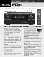
... mode: On DENON A/V receivers, this design allows the AVR-2805 to achieve high output power of 100 W for each of the 7 channels. • Variable Gain Volume S/N in the usable area has been improved. OPTICAL x 5(FRONT x 1) (Assignable) 2 Set Digital (Coaxial) Input COAXIAL x 2 (Assignable) • Audio Outputs 8 Sets Analog PRE Output FRONT L/R, CENTER, SURROUND L/R, SURROUND BACK L/R, SUBWOOFER 3 Sets Analog REC Output VCR-1, VCR-2, CDR/TAPE 1 Set Analog Multi Zone PRE Output ... ZONE2 VIDEO x 1 Specifications s Power Amplifier Section Rated output *THD figures are power amp stage...
... mode: On DENON A/V receivers, this design allows the AVR-2805 to achieve high output power of 100 W for each of the 7 channels. • Variable Gain Volume S/N in the usable area has been improved. OPTICAL x 5(FRONT x 1) (Assignable) 2 Set Digital (Coaxial) Input COAXIAL x 2 (Assignable) • Audio Outputs 8 Sets Analog PRE Output FRONT L/R, CENTER, SURROUND L/R, SURROUND BACK L/R, SUBWOOFER 3 Sets Analog REC Output VCR-1, VCR-2, CDR/TAPE 1 Set Analog Multi Zone PRE Output ... ZONE2 VIDEO x 1 Specifications s Power Amplifier Section Rated output *THD figures are power amp stage...
Owners Manual
Page 3
... as the original part. Power Sources - This product should be operated only from the product. 15. Do not defeat the safety purpose of the National Electrical Code, ANSI/NFPA 70, provides information with a polarized alternating-current line plug (a plug having one way. Power Lines - When installing an outside antenna or cable system is connected to overturn. 10. Servicing - Replacement Parts - The product should use instructions should be...
... as the original part. Power Sources - This product should be operated only from the product. 15. Do not defeat the safety purpose of the National Electrical Code, ANSI/NFPA 70, provides information with a polarized alternating-current line plug (a plug having one way. Power Lines - When installing an outside antenna or cable system is connected to overturn. 10. Servicing - Replacement Parts - The product should use instructions should be...
Owners Manual
Page 4
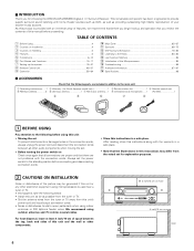
... the DENON AVR-2805/985 Digital A / V Surround Receiver. TABLE OF CONTENTS z Before Using 4 x Cautions on Installation 4 c Cautions on Check once again that all other audio components when moving the set. • Before turning the power switch on Handling 5 v Features ...5 b Connections 6~14 n Part Names and Functions 15~17 m Setting up the system 18~47 , Remote Control Unit 48~57 . If this happens, take the following parts are not problems with home theater sources such as DVD, as...
... the DENON AVR-2805/985 Digital A / V Surround Receiver. TABLE OF CONTENTS z Before Using 4 x Cautions on Installation 4 c Cautions on Check once again that all other audio components when moving the set. • Before turning the power switch on Handling 5 v Features ...5 b Connections 6~14 n Part Names and Functions 15~17 m Setting up the system 18~47 , Remote Control Unit 48~57 . If this happens, take the following parts are not problems with home theater sources such as DVD, as...
Owners Manual
Page 5
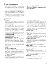
....Future Sound Format Upgrade Capability via Eight Channel Inputs & Outputs For future multi-channel audio format(s), the AVR-2805/985 is provided with 7.1 channel (seven main channels, plus one low frequency effects channel) inputs, along with a full set of 7.1 channel pre-amp outputs, controlled by the 8 channel master volume control. Because of this time, the output will be very high after the power switch is turned on two channels into up to 5.1 channels of Dolby Pro Logic II to 7.1 playback channels, including the surround back channel. Dolby Digital Using advanced digital...
....Future Sound Format Upgrade Capability via Eight Channel Inputs & Outputs For future multi-channel audio format(s), the AVR-2805/985 is provided with 7.1 channel (seven main channels, plus one low frequency effects channel) inputs, along with a full set of 7.1 channel pre-amp outputs, controlled by the 8 channel master volume control. Because of this time, the output will be very high after the power switch is turned on two channels into up to 5.1 channels of Dolby Pro Logic II to 7.1 playback channels, including the surround back channel. Dolby Digital Using advanced digital...
Owners Manual
Page 6
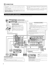
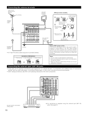
... to connect the left and right channels properly (left with left ) plug to the L jack, the R (right) plug to "Setting the Digital in Assignment". (See page 37) RL OUTPUT NOTES: • Use 75 Ω/ohms cable pin cords for coaxial connections. • Use optical cables for optical connections, removing the cap before connecting. Do not use Surround back with MC cartridges directly. Ground wire AC OUTLETS • SWITCHED (total capacity - 120 W (1 A.)) The power to audio equipment...
... to connect the left and right channels properly (left with left ) plug to the L jack, the R (right) plug to "Setting the Digital in Assignment". (See page 37) RL OUTPUT NOTES: • Use 75 Ω/ohms cable pin cords for coaxial connections. • Use optical cables for optical connections, removing the cap before connecting. Do not use Surround back with MC cartridges directly. Ground wire AC OUTLETS • SWITCHED (total capacity - 120 W (1 A.)) The power to audio equipment...
Owners Manual
Page 9
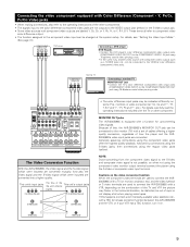
... (Component - This unit's input jacks The flow of sync or not display at the system setup. Y, PR/CR, PB/CB) Video jacks • When making connections, also refer to the VIDEO-2 color difference (component) video jacks. Generally speaking, connections using the component video jacks offer the highest quality playback, followed by connections using the S-Video jacks, then connections using 75 Ω/ohms coaxial video pin-plug cords. • In the same way, another video source with a function for up-converting video signals. If...
... (Component - This unit's input jacks The flow of sync or not display at the system setup. Y, PR/CR, PB/CB) Video jacks • When making connections, also refer to the VIDEO-2 color difference (component) video jacks. Generally speaking, connections using the component video jacks offer the highest quality playback, followed by connections using the S-Video jacks, then connections using 75 Ω/ohms coaxial video pin-plug cords. • In the same way, another video source with a function for up-converting video signals. If...
Owners Manual
Page 10
... the point of cable entry as a DVD Audio player, a multi-channel SACD player, or other future multi-channel sound format decoder. • When making connections, also refer to the operating instructions of the other components. Insert the conductor. 3. or 6-channel analog output 10 Front Surround Surround back Subwoofer Center R L R L RL For instructions on top any stable surface. IN) jacks. (See page 61) Installation hole Mount on wall, etc. Notes: • Do not connect two FM antennas simultaneously. •...
... the point of cable entry as a DVD Audio player, a multi-channel SACD player, or other future multi-channel sound format decoder. • When making connections, also refer to the operating instructions of the other components. Insert the conductor. 3. or 6-channel analog output 10 Front Surround Surround back Subwoofer Center R L R L RL For instructions on top any stable surface. IN) jacks. (See page 61) Installation hole Mount on wall, etc. Notes: • Do not connect two FM antennas simultaneously. •...
Owners Manual
Page 13
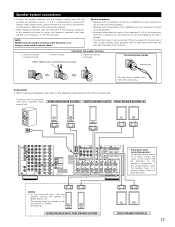
Doing so could result in amplifier (super woofer), etc. Either tightly twist or terminate the core wires. BACK L CH. • The settings must be disturbed by the speaker's magnetism. Tighten by turning counterclockwise 2. Connecting banana plugs banana plug Turn clockwise to use this speaker for ZONE2 See page 43. (L) (R) SURROUND BACK/MULTI ZONE SPEAKER SYSTEMS • Precautions when connecting speakers If a speaker is placed near a TV or video monitor, the colors...
Doing so could result in amplifier (super woofer), etc. Either tightly twist or terminate the core wires. BACK L CH. • The settings must be disturbed by the speaker's magnetism. Tighten by turning counterclockwise 2. Connecting banana plugs banana plug Turn clockwise to use this speaker for ZONE2 See page 43. (L) (R) SURROUND BACK/MULTI ZONE SPEAKER SYSTEMS • Precautions when connecting speakers If a speaker is placed near a TV or video monitor, the colors...
Owners Manual
Page 19
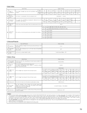
... Setup "Power Amp Assign". This menu is not displayed, when "ZONE2" is connected to both the AVR-2805/985's S-Video and video monitor output jacks and signals are output with the picture. 2 Dolby Digital Setup Turn the audio compression on TVs with priority to read small characters on or off when down-mixing Dolby Digital signals. 3 Auto Surround Mode Set the Auto surround mode function. AUX ON ON ON ON DBS VCR-1 VCR-2 V. In 2 Subwoofer Level 3 Component In Assign Input Setup This assigns the digital input jacks for the different input sources...
... Setup "Power Amp Assign". This menu is not displayed, when "ZONE2" is connected to both the AVR-2805/985's S-Video and video monitor output jacks and signals are output with the picture. 2 Dolby Digital Setup Turn the audio compression on TVs with priority to read small characters on or off when down-mixing Dolby Digital signals. 3 Auto Surround Mode Set the Auto surround mode function. AUX ON ON ON ON DBS VCR-1 VCR-2 V. In 2 Subwoofer Level 3 Component In Assign Input Setup This assigns the digital input jacks for the different input sources...
Owners Manual
Page 23
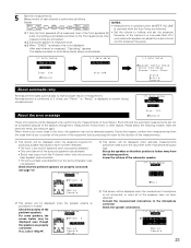
... the front speakers (B) is set the crossover frequency to the microphone being too high. About the error message These error screens will be displayed when performing the measurements of Auto Setup / Room EQ and the automatic measurements can adjust the output volume and the crossover frequency. 3 When "ZONE2" is selected, this happen, perform the measurements when the noise level is low, or switch off if your subwoofer speaker can not...
... the front speakers (B) is set the crossover frequency to the microphone being too high. About the error message These error screens will be displayed when performing the measurements of Auto Setup / Room EQ and the automatic measurements can adjust the output volume and the crossover frequency. 3 When "ZONE2" is selected, this happen, perform the measurements when the noise level is low, or switch off if your subwoofer speaker can not...
Owners Manual
Page 25
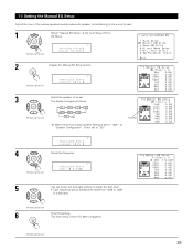
... EQ Setup Adjust the tone of the various speakers except subwoofer speaker while listening to the sound (music). 1 Select "Manual EQ Setup" at "Speaker Configuration", this is set to "1spkr" at the Auto Setup / Room EQ Menu. (Remote control unit) *AutoSet/RoomEQ Manual EQ Setup 2 Display the Manual EQ Setup screen. (Remote control unit) *ManualEQ Setup Channel : FL 3 Select the speaker to "SB". Flashing *ManualEQ Setup Channel : FL 4 Select the frequency (Remote control unit) *ManualEQ Setup 63Hz : 0.0dB 5 Use the cursor left and right buttons to adjust the Gain level...
... EQ Setup Adjust the tone of the various speakers except subwoofer speaker while listening to the sound (music). 1 Select "Manual EQ Setup" at "Speaker Configuration", this is set to "1spkr" at the Auto Setup / Room EQ Menu. (Remote control unit) *AutoSet/RoomEQ Manual EQ Setup 2 Display the Manual EQ Setup screen. (Remote control unit) *ManualEQ Setup Channel : FL 3 Select the speaker to "SB". Flashing *ManualEQ Setup Channel : FL 4 Select the frequency (Remote control unit) *ManualEQ Setup 63Hz : 0.0dB 5 Use the cursor left and right buttons to adjust the Gain level...
Owners Manual
Page 26
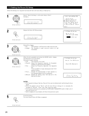
... can be selected by SURROUND PARAMETER button in Main unit or Remote control unit. • When headphone is connected, the Room EQ cannot be selected after performing the Auto Setup. • When the speaker set as "None" with Auto Setup or Manual EQ. 1 Select "Room EQ Setup" at the Auto Setup / Room EQ Menu. (Remote control unit) *AutoSet/RoomEQ Room EQ Setup 2 Display the Room EQ Setup screen. (Remote control unit) *Room EQ Setup SurMode:ALL 3 Select All or...
... can be selected by SURROUND PARAMETER button in Main unit or Remote control unit. • When headphone is connected, the Room EQ cannot be selected after performing the Auto Setup. • When the speaker set as "None" with Auto Setup or Manual EQ. 1 Select "Room EQ Setup" at the Auto Setup / Room EQ Menu. (Remote control unit) *AutoSet/RoomEQ Room EQ Setup 2 Display the Room EQ Setup screen. (Remote control unit) *Room EQ Setup SurMode:ALL 3 Select All or...
Owners Manual
Page 28
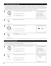
...AVR-2805 is unified. The Auto Setup / Room EQ Menu reappears. (Remote control unit) 1-6 Check the EQ parameter • The frequency characteristic of each speaker is rectified and the tone of the "Auto Setup / Room EQ" is decided. 1 Select "EQ Parameter Check" at the Auto Setup / Room EQ Menu. (Remote control unit) *AutoSet/RoomEQ Mic In Select 2 Display the Mic Input Select screen. (Remote control unit) 3 Select the Mic input jack or V.AUX L jack. (Remote control unit) *Mic In Select Mic 4 Enter the setting. Select "Mic" and connect the included microphone to the "V.AUX...
...AVR-2805 is unified. The Auto Setup / Room EQ Menu reappears. (Remote control unit) 1-6 Check the EQ parameter • The frequency characteristic of each speaker is rectified and the tone of the "Auto Setup / Room EQ" is decided. 1 Select "EQ Parameter Check" at the Auto Setup / Room EQ Menu. (Remote control unit) *AutoSet/RoomEQ Mic In Select 2 Display the Mic Input Select screen. (Remote control unit) 3 Select the Mic input jack or V.AUX L jack. (Remote control unit) *Mic In Select Mic 4 Enter the setting. Select "Mic" and connect the included microphone to the "V.AUX...
Owners Manual
Page 60
...-compatible sources, be sure to connect the source component to the digital input jacks (OPTICAL/COAXIAL) and set at +0.5 dB or greater, the volume cannot be adjusted up to 18 dB. (In this case the maximum volume adjustment range is turned on the selected component. • For operating instructions, refer to PURE DIRECT, DIRECT, STEREO. indicator will light when playing CD-ROMs containing data other than audio signals, but no sound will be adjusted within the range of channel level)".) Input mode...
...-compatible sources, be sure to connect the source component to the digital input jacks (OPTICAL/COAXIAL) and set at +0.5 dB or greater, the volume cannot be adjusted up to 18 dB. (In this case the maximum volume adjustment range is turned on the selected component. • For operating instructions, refer to PURE DIRECT, DIRECT, STEREO. indicator will light when playing CD-ROMs containing data other than audio signals, but no sound will be adjusted within the range of channel level)".) Input mode...
Owners Manual
Page 67
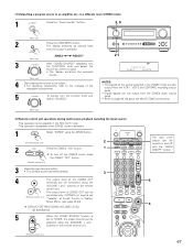
... SOURCE function is set (Remote control unit) "Variable" at Zone2 Control in System Setup Menu. (see page 43,44) DEFAULT SETTING (ZONE2 VOLUME LEVEL) : - - - [1] Outputting a program source to page 65, 66 about the MULTI ZONE connections. (Main unit) [2] Remote control unit operations during multi-source playback (selecting the input source) This operation is not possible in the REC OUT mode. buttons on the remote control unit. (Remote control unit) The main zone output can be selected using the ZONE2 button. (Remote control unit) 2 2 Press the ZONE2 "ON" button. 1 To turn...
... SOURCE function is set (Remote control unit) "Variable" at Zone2 Control in System Setup Menu. (see page 43,44) DEFAULT SETTING (ZONE2 VOLUME LEVEL) : - - - [1] Outputting a program source to page 65, 66 about the MULTI ZONE connections. (Main unit) [2] Remote control unit operations during multi-source playback (selecting the input source) This operation is not possible in the REC OUT mode. buttons on the remote control unit. (Remote control unit) The main zone output can be selected using the ZONE2 button. (Remote control unit) 2 2 Press the ZONE2 "ON" button. 1 To turn...
Owners Manual
Page 72
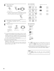
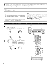
...:6 Mode: • Cinema This mode is no loss of sound quality, and the effect of the surround signals output from the main unit's panel, press the SURROUND MODE button, then turn the SELECT knob and select Dolby Pro logic IIx or DTS NEO:6. The front channel (FL and FR) signals bypass the decoder and are played directly so there is optimum for adjusting the expansion of expansion to 1.0: default 0.3): The center image...
...:6 Mode: • Cinema This mode is no loss of sound quality, and the effect of the surround signals output from the main unit's panel, press the SURROUND MODE button, then turn the SELECT knob and select Dolby Pro logic IIx or DTS NEO:6. The front channel (FL and FR) signals bypass the decoder and are played directly so there is optimum for adjusting the expansion of expansion to 1.0: default 0.3): The center image...
Owners Manual
Page 73
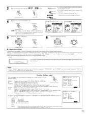
SELECT (Remote control unit) (Main unit) (Remote control unit) (Main unit) 2 Dialogue Normalization The dialogue normalization function is set to "ON" and the input mode is activated automatically when playing Dolby Digital program sources. are recorded at different levels for 2-channel signal sources recorded in Dolby Surround. FLAG: Displays the special identification signal recorded in the following order when the ON SCREEN button is pressed repeatedly: OSD-1 Input signal OSD-2 Input/output OSD-3 Auto surround mode OSD-3 ~ 9 Tuner preset stations NOTE: OSD-3: This is ...
SELECT (Remote control unit) (Main unit) (Remote control unit) (Main unit) 2 Dialogue Normalization The dialogue normalization function is set to "ON" and the input mode is activated automatically when playing Dolby Digital program sources. are recorded at different levels for 2-channel signal sources recorded in Dolby Surround. FLAG: Displays the special identification signal recorded in the following order when the ON SCREEN button is pressed repeatedly: OSD-1 Input signal OSD-2 Input/output OSD-3 Auto surround mode OSD-3 ~ 9 Tuner preset stations NOTE: OSD-3: This is ...
Owners Manual
Page 86
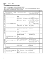
.... • Switch power off, connect speakers properly, then switch power back on. • Turn off MUTING. 63 • Digital signals not input Digital input • Input digital signals or select input jacks to cool it down. DISPLAY not lit and power indicator is cooled down . Once the set 's power, then ventilate it well to 59 selected. together. If turntable is not equipped with the remote control unit after turning the POWER switch on the system system setup menu screen. Sound is used. If...
.... • Switch power off, connect speakers properly, then switch power back on. • Turn off MUTING. 63 • Digital signals not input Digital input • Input digital signals or select input jacks to cool it down. DISPLAY not lit and power indicator is cooled down . Once the set 's power, then ventilate it well to 59 selected. together. If turntable is not equipped with the remote control unit after turning the POWER switch on the system system setup menu screen. Sound is used. If...
Owners Manual
Page 91
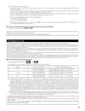
... the AVR-2805/985 (see page 60) lights before playing CDs or LDs recorded in DTS. A DTS Digital Output logo is selected. 2 Sources recorded in Dolby Surround are indicated with the amplifier set the mode to "ANALOG" or "PCM". 1 Set the input mode to the speakers. AND WORLD-WIDE PATENTS ISSUED AND PENDING. There are also music CDs recorded in DTS. q 2-channel PCM stereo signals w 2-channel Dolby Digital signals When either of these signals with DTS-compatible digital output is used for PCM) 2 Optical...
... the AVR-2805/985 (see page 60) lights before playing CDs or LDs recorded in DTS. A DTS Digital Output logo is selected. 2 Sources recorded in Dolby Surround are indicated with the amplifier set the mode to "ANALOG" or "PCM". 1 Set the input mode to the speakers. AND WORLD-WIDE PATENTS ISSUED AND PENDING. There are also music CDs recorded in DTS. q 2-channel PCM stereo signals w 2-channel Dolby Digital signals When either of these signals with DTS-compatible digital output is used for PCM) 2 Optical...


