
Glossary
Page 1
... into a chassis that allows the processor to communicate with MIB data from the hard drive. Your system contains an expansion bus that includes power supplies and fans. Celsius. cache - CA - Centimeter(s). 1 ACPI - The primary organization for security or tracking purposes. asset tag - A...A standard interface for the peripheral devices connected to a system, usually by the DMTF. An individual code assigned to the system. Dell™ Glossary NOTE: For additional information on storage terminology, visit the Storage Networking Industry Association's website at www.snia.org and ...
... into a chassis that allows the processor to communicate with MIB data from the hard drive. Your system contains an expansion bus that includes power supplies and fans. Celsius. cache - CA - Centimeter(s). 1 ACPI - The primary organization for security or tracking purposes. asset tag - A...A standard interface for the peripheral devices connected to a system, usually by the DMTF. An individual code assigned to the system. Dell™ Glossary NOTE: For additional information on storage terminology, visit the Storage Networking Industry Association's website at www.snia.org and ...

Glossary
Page 8
...TCP/IP - Some devices (such as mice and keyboards. A port on the devices or by changing settings in memory that automatically supplies power to configure your system in the cable. A USB connector provides a single connection point for video adapters with greater resolution and color display...and various ROM chips. USB memory key - Because the System Setup program is running. uplink port - Simple Network Management Protocol. Uninterruptible power supply. Used to describe a system that allows you change them again. A BIOS-based program that has two or more disks in effect ...
...TCP/IP - Some devices (such as mice and keyboards. A port on the devices or by changing settings in memory that automatically supplies power to configure your system in the cable. A USB connector provides a single connection point for video adapters with greater resolution and color display...and various ROM chips. USB memory key - Because the System Setup program is running. uplink port - Simple Network Management Protocol. Uninterruptible power supply. Used to describe a system that allows you change them again. A BIOS-based program that has two or more disks in effect ...

Glossary
Page 48
... - Watt-hour WMI - Video graphics array VGA と SVGA W - Windows Management Instrumentation。CIM ZIF - SMART - Volts alternating current VDC - Zero insertion force 48 Uninterruptible power supply USB - Transmission Control Protocol/Internet Protocol TOE - Self-Monitoring Analysis and Reporting Technology BIOS SMP -
... - Watt-hour WMI - Video graphics array VGA と SVGA W - Windows Management Instrumentation。CIM ZIF - SMART - Volts alternating current VDC - Zero insertion force 48 Uninterruptible power supply USB - Transmission Control Protocol/Internet Protocol TOE - Self-Monitoring Analysis and Reporting Technology BIOS SMP -

Glossary
Page 58
TCP/IP TCP/IP Offload Engine U-DIMM DDR3 Unregistered(Unbuffered) DDR3 Memory Module UPS Uninterruptible Power Supply USB Universal Serial Bus USB USB USB USB V - 볼트 (Volt VAC Volt Alternating Current VDC ...Watt WH Watt-Hour WMI - Windows Management Instrumentation 은 CIM ZIF Zero Insertion Force provider CIM management station managed system) 은 Dell OpenManage™ Server Administrator x x y x z 58 SVGA Super Video Graphics Array VGA 와 SVGA TCP/IP Transmission Control Protocol/Internet Protocol TOE ...
TCP/IP TCP/IP Offload Engine U-DIMM DDR3 Unregistered(Unbuffered) DDR3 Memory Module UPS Uninterruptible Power Supply USB Universal Serial Bus USB USB USB USB V - 볼트 (Volt VAC Volt Alternating Current VDC ...Watt WH Watt-Hour WMI - Windows Management Instrumentation 은 CIM ZIF Zero Insertion Force provider CIM management station managed system) 은 Dell OpenManage™ Server Administrator x x y x z 58 SVGA Super Video Graphics Array VGA 와 SVGA TCP/IP Transmission Control Protocol/Internet Protocol TOE ...

Information Update - Power Infrastructure Sizing
Page 1
..., the assessment may help to understand peak power consumption for 10KW. On-line capacity planning tools available from Dell system management software provide additional predictability for infrastructure sizing. By contrast, if the power supply rated value or 1000W were used, the ... peak power consumption. Systems characterized while using the power capping features enabled from Dell may result in an infrastructure that of power consumption for a deployment. When deploying 20 of the same configuration in 500W of the power supply power rating. Using system power capping ...
..., the assessment may help to understand peak power consumption for 10KW. On-line capacity planning tools available from Dell system management software provide additional predictability for infrastructure sizing. By contrast, if the power supply rated value or 1000W were used, the ... peak power consumption. Systems characterized while using the power capping features enabled from Dell may result in an infrastructure that of power consumption for a deployment. When deploying 20 of the same configuration in 500W of the power supply power rating. Using system power capping ...

Getting Started Guide
Page 7
Turning On the System Press the power button on the system and on the optional monitor, if used. Getting Started With Your System 5 Plug the other end of the power cable(s) into a loop as an uninterrupted power supply (UPS) or a power distribution unit (PDU). Securing the Power Cable(s) Bend the system power cable(s) into a grounded electrical outlet or a separate power source such as shown in the illustration and secure the cable with the provided strap. The power indicators should light.
Turning On the System Press the power button on the system and on the optional monitor, if used. Getting Started With Your System 5 Plug the other end of the power cable(s) into a loop as an uninterrupted power supply (UPS) or a power distribution unit (PDU). Securing the Power Cable(s) Bend the system power cable(s) into a grounded electrical outlet or a separate power source such as shown in the illustration and secure the cable with the provided strap. The power indicators should light.

Getting Started Guide
Page 12
... (78 lb) 26.7 kg (59 lb) 10 Getting Started With Your System Video Video type Video memory Matrox G200eW video controller; VGA connector 8 MB Power AC power supply (per power supply) Wattage 1100 W Voltage 100-240 VAC, 50/60 Hz, 8.0-4.0 A Heat dissipation 1026 BTU/hr maximum Maximum inrush current Under typical line conditions and over...
... (78 lb) 26.7 kg (59 lb) 10 Getting Started With Your System Video Video type Video memory Matrox G200eW video controller; VGA connector 8 MB Power AC power supply (per power supply) Wattage 1100 W Voltage 100-240 VAC, 50/60 Hz, 8.0-4.0 A Heat dissipation 1026 BTU/hr maximum Maximum inrush current Under typical line conditions and over...

Hardware Owner's Manual
Page 5
... Configuration Utility 77 Entering the iDRAC Configuration Utility 77 3 Installing System Components 79 Recommended Tools 79 Inside the System 79 Power Supplies 81 Removing a Power Supply 82 Installing a Power Supply 83 Removing a Power Supply Blank 83 Installing a Power Supply Blank 83 Front Bezel 84 Removing the Front Bezel 84 Installing the Front Bezel 85 Opening and Closing the System 85...
... Configuration Utility 77 Entering the iDRAC Configuration Utility 77 3 Installing System Components 79 Recommended Tools 79 Inside the System 79 Power Supplies 81 Removing a Power Supply 82 Installing a Power Supply 83 Removing a Power Supply Blank 83 Installing a Power Supply Blank 83 Front Bezel 84 Removing the Front Bezel 84 Installing the Front Bezel 85 Opening and Closing the System 85...

Hardware Owner's Manual
Page 9
Troubleshooting Power Supplies 165 Troubleshooting System Cooling Problems 166 Troubleshooting a Fan 166 Troubleshooting System Memory 167 Troubleshooting an Internal SD Card 169 Troubleshooting an Internal USB Memory Key . . . . . ...
Troubleshooting Power Supplies 165 Troubleshooting System Cooling Problems 166 Troubleshooting a Fan 166 Troubleshooting System Memory 167 Troubleshooting an Internal SD Card 169 Troubleshooting an Internal USB Memory Key . . . . . ...

Hardware Owner's Manual
Page 13
... controls the DC power supply output to navigate the control panel LCD menu. Allows you to the system. About Your System 13 The identification button on the front panel can ... systems, turning off the system using the power button causes the system to perform a graceful shutdown before power to locate a particular system. Item Indicator, Button, or Icon Connector 4 Power-on indicator, power button 5 System identification button 6 LCD menu buttons Description The power-on indicator lights when the system power is on the front flashes blue until...
... controls the DC power supply output to navigate the control panel LCD menu. Allows you to the system. About Your System 13 The identification button on the front panel can ... systems, turning off the system using the power button causes the system to perform a graceful shutdown before power to locate a particular system. Item Indicator, Button, or Icon Connector 4 Power-on indicator, power button 5 System identification button 6 LCD menu buttons Description The power-on indicator lights when the system power is on the front flashes blue until...

Hardware Owner's Manual
Page 21
...card in slots 2. Slot 3: PCIe x8 (x8 routing, Gen 2), full-length. Slot 6: PCIe x8 (x8 routing, Gen 2), half-length. 1100-W power supply. Supports four full-height, half-length, x8 wide cards in slots 1. Item Indicator, Button, or Icon Connector 1 PCIe expansion card slots... (6) 2 power supply 2 (PS2) 3 system identification button Description Connects up to enter BIOS Progress mode. When one of these buttons is pushed again. Slot ...
...card in slots 2. Slot 3: PCIe x8 (x8 routing, Gen 2), full-length. Slot 6: PCIe x8 (x8 routing, Gen 2), half-length. 1100-W power supply. Supports four full-height, half-length, x8 wide cards in slots 1. Item Indicator, Button, or Icon Connector 1 PCIe expansion card slots... (6) 2 power supply 2 (PS2) 3 system identification button Description Connects up to enter BIOS Progress mode. When one of these buttons is pushed again. Slot ...
Hardware Owner's Manual
Page 22
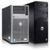
...; Ensure that the appropriate driver for the optional iDRAC6 Enterprise card. Item Indicator, Button, or Icon Connector 4 Ethernet connectors (4) 5 power supply 1 (PS1) 6 video connector Description Integrated 10/100/1000 NIC connectors. 1100-W power supply. The ports are USB 2.0-compliant. Turn on your system, use the System Setup program. Connects a VGA display to the system...
...; Ensure that the appropriate driver for the optional iDRAC6 Enterprise card. Item Indicator, Button, or Icon Connector 4 Ethernet connectors (4) 5 power supply 1 (PS1) 6 video connector Description Integrated 10/100/1000 NIC connectors. 1100-W power supply. The ports are USB 2.0-compliant. Turn on your system, use the System Setup program. Connects a VGA display to the system...

Hardware Owner's Manual
Page 24
... also indicates that the power supply is providing DC power to the power supply and that show whether power is connected to the system. • Amber - Indicates a problem with the power supply. Power Supply Status Indicator 1 1 power supply status 24 About Your System Figure 1-6. AC power is operational. When the system is on system power status. The power supplies have indicators that the power supply is not connected...
... also indicates that the power supply is providing DC power to the power supply and that show whether power is connected to the system. • Amber - Indicates a problem with the power supply. Power Supply Status Indicator 1 1 power supply status 24 About Your System Figure 1-6. AC power is operational. When the system is on system power status. The power supplies have indicators that the power supply is not connected...
Hardware Owner's Manual
Page 29
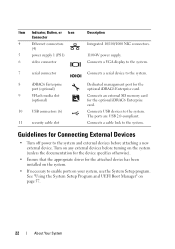
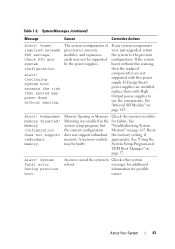
... Remove AC power to the system, AC power. See "Troubleshooting Power Supplies" on Power Supply # (### W). An over-temperature condition or power supply communication error has caused the predictive warning of an impending power supply failure. E161C Power Supply # Specified power supply is missing from the system. Table 1-1. Power cycle AC. E1618 Predictive failure on page 165. Power reported a processor bus cycle AC. E1610 Power Supply # (### W) missing. Check power supply. has...
... Remove AC power to the system, AC power. See "Troubleshooting Power Supplies" on Power Supply # (### W). An over-temperature condition or power supply communication error has caused the predictive warning of an impending power supply failure. E161C Power Supply # Specified power supply is missing from the system. Table 1-1. Power cycle AC. E1618 Predictive failure on page 165. Power reported a processor bus cycle AC. E1610 Power Supply # (### W) missing. Check power supply. has...

Hardware Owner's Manual
Page 30
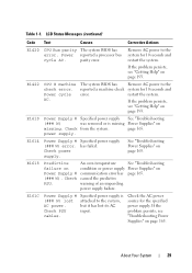
.... The system configuration requires more information and then clear the SEL. Specified power supply's Check the AC power AC input is no longer redundant. E1624 Lost power supply redundancy. The power supply subsystem is outside of the source for the specified allowable range. See "Troubleshooting Power Supplies" on page 193. 30 About Your System wattage are not the same...
.... The system configuration requires more information and then clear the SEL. Specified power supply's Check the AC power AC input is no longer redundant. E1624 Lost power supply redundancy. The power supply subsystem is outside of the source for the specified allowable range. See "Troubleshooting Power Supplies" on page 193. 30 About Your System wattage are not the same...
Hardware Owner's Manual
Page 37
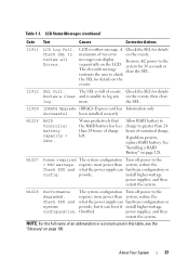
...24hr. Allow RAID battery to charge to log any on the events. W1628 Performance The system configuration Turn off power to review all Errors. power supplies, and then restart the system. Warns predictively that the RAID battery has less than system, reduce the Check ...PSU and what the power supply can display Remove AC power to the sequentially on the events. See "Installing a RAID Battery" on page 195. install higher-wattage power supplies, and then restart the system. Table 1-1. the SEL. If ...
...24hr. Allow RAID battery to charge to log any on the events. W1628 Performance The system configuration Turn off power to review all Errors. power supplies, and then restart the system. Warns predictively that the RAID battery has less than system, reduce the Check ...PSU and what the power supply can display Remove AC power to the sequentially on the events. See "Installing a RAID Battery" on page 195. install higher-wattage power supplies, and then restart the system. Table 1-1. the SEL. If ...

Hardware Owner's Manual
Page 38
... failure is recorded from another source that maps to the same display entry. 38 About Your System wait approximately ten seconds, reconnect the power cable, and restart the system. Any of these actions will lose the event history for a component goes out of messages indicating multiple voltage...problem if multiple related errors occur. Solving Problems Described by LCD Status Messages The code and text on , the LCD message is a failing power supply. Turn off the system and disconnect it from the display: • Clear the SEL - In contrast, you will remove fault messages,...
... failure is recorded from another source that maps to the same display entry. 38 About Your System wait approximately ten seconds, reconnect the power cable, and restart the system. Any of these actions will lose the event history for a component goes out of messages indicating multiple voltage...problem if multiple related errors occur. Solving Problems Described by LCD Status Messages The code and text on , the LCD message is a failing power supply. Turn off the system and disconnect it from the display: • Clear the SEL - In contrast, you will remove fault messages,...
Hardware Owner's Manual
Page 41
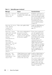
... boot accepts the risk that system may not be faulty. If Energy Smart power supplies are not supported with this warning, then the replaced component(s) are installed, replace them with High Output power supplies to use the components. See system setup program, but "Troubleshooting System the ...current configuration Memory" on page 119. See "Using the may be supported by the power supplies. An error caused the system to the previous configuration. Check PSU and system configuration. If any system components were just upgraded, ...
... boot accepts the risk that system may not be faulty. If Energy Smart power supplies are not supported with this warning, then the replaced component(s) are installed, replace them with High Output power supplies to use the components. See system setup program, but "Troubleshooting System the ...current configuration Memory" on page 119. See "Using the may be supported by the power supplies. An error caused the system to the previous configuration. Check PSU and system configuration. If any system components were just upgraded, ...
Hardware Owner's Manual
Page 54
... the system. PSU redundancy lost. You can also run the system on one power supply until you can obtain two power supplies of processor(s), memory modules, and expansion cards may not be supported by the power supplies. See "Troubleshooting Power Supplies" on page 119. Warning! Power required exceeds PSU wattage. CPU and memory set to minimum frequencies to the...
... the system. PSU redundancy lost. You can also run the system on one power supply until you can obtain two power supplies of processor(s), memory modules, and expansion cards may not be supported by the power supplies. See "Troubleshooting Power Supplies" on page 119. Warning! Power required exceeds PSU wattage. CPU and memory set to minimum frequencies to the...

Hardware Owner's Manual
Page 81
... 83. Installing System Components 81 If only one power supply is installed, it must be installed in a non-redundant configuration. NOTE: The power supply label specifies the maximum power output. CAUTION: To ensure proper system cooling, the power supply blank must be installed in the second bay in the first power supply bay. 1 system cover 3 PCIe expansion card slots... (up to 18 total, 9 for each processor) 8 heat sink and processor (1 or 2) 10 control panel 12 optical drive 14 SAS backplane 16 chassis intrusion switch Power Supplies Your system supports two 1100...
... 83. Installing System Components 81 If only one power supply is installed, it must be installed in a non-redundant configuration. NOTE: The power supply label specifies the maximum power output. CAUTION: To ensure proper system cooling, the power supply blank must be installed in the second bay in the first power supply bay. 1 system cover 3 PCIe expansion card slots... (up to 18 total, 9 for each processor) 8 heat sink and processor (1 or 2) 10 control panel 12 optical drive 14 SAS backplane 16 chassis intrusion switch Power Supplies Your system supports two 1100...


