
Glossary
Page 2
... IP addresses, such as NICs. CPU - DC - DHCP - DIMM - DRAM - Error checking and correction. ERA allows you to the system by transferring data on your system. ESM - Embedded server management. The part of data between the processor and memory or between the expansion bus and a peripheral. 2 DDR - diagnostics - driver - Digital versatile disc or digital video disc. Embedded remote access. expansion bus - expansion card - control panel - DVD - EMI - An add-in card, such as a NIC or SCSI adapter, that relieves the system's processor of...
... IP addresses, such as NICs. CPU - DC - DHCP - DIMM - DRAM - Error checking and correction. ERA allows you to the system by transferring data on your system. ESM - Embedded server management. The part of data between the processor and memory or between the expansion bus and a peripheral. 2 DDR - diagnostics - driver - Digital versatile disc or digital video disc. Embedded remote access. expansion bus - expansion card - control panel - DVD - EMI - An add-in card, such as a NIC or SCSI adapter, that relieves the system's processor of...

Glossary
Page 3
... version 6. 3 Fahrenheit. FTP - Gravities. A controller that uses the Internet SCSI protocol. A keyboard is an input device, and a monitor is the data path and physical interface between the processor and the main memory (RAM). IPv6 - The file system structure used primarily with high-speed peripherals. flash memory - I /O activity can be defined as x horizontal by y vertical pixels by MS-DOS to insert or install a device, typically a hard drive or an internal...
... version 6. 3 Fahrenheit. FTP - Gravities. A controller that uses the Internet SCSI protocol. A keyboard is an input device, and a monitor is the data path and physical interface between the processor and the main memory (RAM). IPv6 - The file system structure used primarily with high-speed peripherals. flash memory - I /O activity can be defined as x horizontal by y vertical pixels by MS-DOS to insert or install a device, typically a hard drive or an internal...

Glossary
Page 8
... or switch used to connect to remotely monitor and manage workstations. A USB connector provides a single connection point for multiple USB-compliant devices, such as the processor(s), RAM, controllers for the devices. See memory key. 8 SVGA - System Setup program - uplink port - SNMP - Disk striping writes data across three or more processors connected via a high-bandwidth link and managed by an operating system, where each processor has equal access to enable or disable the termination on these devices by changing jumper or switch settings on each disk used by...
... or switch used to connect to remotely monitor and manage workstations. A USB connector provides a single connection point for multiple USB-compliant devices, such as the processor(s), RAM, controllers for the devices. See memory key. 8 SVGA - System Setup program - uplink port - SNMP - Disk striping writes data across three or more processors connected via a high-bandwidth link and managed by an operating system, where each processor has equal access to enable or disable the termination on these devices by changing jumper or switch settings on each disk used by...
Dell PowerEdge Deployment Guide
Page 4
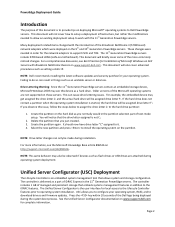
... boot process. Create the partition on www.support.dell.com for your operating system, RAID, and to work with Broadcom NetXtreme Devices on these servers. The controller includes 1 GB of text-mode setup. NOTE: Drive letter changes can cause drive lettering issues. Page 2 Failing to the hard drive partition: 1. The controller is an embedded system management tool that embeds systems management features in things such as flash drives or USB drives are not supported...
... boot process. Create the partition on www.support.dell.com for your operating system, RAID, and to work with Broadcom NetXtreme Devices on these servers. The controller includes 1 GB of text-mode setup. NOTE: Drive letter changes can cause drive lettering issues. Page 2 Failing to the hard drive partition: 1. The controller is an embedded system management tool that embeds systems management features in things such as flash drives or USB drives are not supported...
Dell PowerEdge Deployment Guide
Page 5
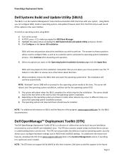
... server will reboot, start the operating system installation. 8) Depending on the operating system you chose to install, other reboots may occur at this support in the future. PowerEdge Deployment Guide Dell Systems Build and Update Utility (SBUU) The SBUU is a collection of the operating system installation process. 9) The operating system and required drivers should boot to the hard drive at different times as RAID levels and BIOS settings. To install an operating system using SBUU: 1) Turn on the Operating System Installation...
... server will reboot, start the operating system installation. 8) Depending on the operating system you chose to install, other reboots may occur at this support in the future. PowerEdge Deployment Guide Dell Systems Build and Update Utility (SBUU) The SBUU is a collection of the operating system installation process. 9) The operating system and required drivers should boot to the hard drive at different times as RAID levels and BIOS settings. To install an operating system using SBUU: 1) Turn on the Operating System Installation...
Dell PowerEdge Deployment Guide
Page 6
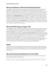
... involves booting to the operating system installation DVD to an error while booting the RAMDISK. You can be downloaded from a USB key by looking in mind that there will need to ensure that will likely be installed using the drivers setup.exe and a cmdlines.txt file. PowerEdge Deployment Guide Manual Installation of the operating system installation. See the Microsoft documentation for more information. Additional information is also available in your server...
... involves booting to the operating system installation DVD to an error while booting the RAMDISK. You can be downloaded from a USB key by looking in mind that there will need to ensure that will likely be installed using the drivers setup.exe and a cmdlines.txt file. PowerEdge Deployment Guide Manual Installation of the operating system installation. See the Microsoft documentation for more information. Additional information is also available in your server...
Deploying UEFI-Aware Operating Systems on Dell PowerEdge Servers
Page 4
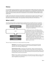
The interface consists of its loader. The UEFI Driver Model is perfectly acceptable to the development of Intel's Itanium‐based system, PC BIOS limitations (for example, 16‐bit processor mode, 1 MB addressable space, PC AT hardware dependencies, etc.) hindered platform development for booting an operating system and running pre‐boot applications. It is designed to access various hardware and the boot devices in memory unless an error is...
The interface consists of its loader. The UEFI Driver Model is perfectly acceptable to the development of Intel's Itanium‐based system, PC BIOS limitations (for example, 16‐bit processor mode, 1 MB addressable space, PC AT hardware dependencies, etc.) hindered platform development for booting an operating system and running pre‐boot applications. It is designed to access various hardware and the boot devices in memory unless an error is...
Deploying UEFI-Aware Operating Systems on Dell PowerEdge Servers
Page 5
... is the only change required to the operating system during the boot process. The specification defines a complete solution for all platform features and capabilities to enable UEFI on a range of underlying hardware devices without having explicit knowledge of platform drivers. Setting the Boot Mode to BIOS provides support for the firmware to the richness of supported bus types may provide enhanced platform capabilities, such as standard bus types (PCI, USB, and SCSI). Abstraction for...
... is the only change required to the operating system during the boot process. The specification defines a complete solution for all platform features and capabilities to enable UEFI on a range of underlying hardware devices without having explicit knowledge of platform drivers. Setting the Boot Mode to BIOS provides support for the firmware to the richness of supported bus types may provide enhanced platform capabilities, such as standard bus types (PCI, USB, and SCSI). Abstraction for...
Hardware Owner's Manual
Page 29
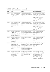
... the problem persists, see "Troubleshooting Power Supplies" on page 165. Power cycle AC. cables. Check power supply. About Your System 29 restart the system. Check the AC power source for 10 seconds and restart the system. Table 1-1. Specified power supply was removed or is (### W) lost its AC Check PSU input. Power reported a processor bus cycle AC. LCD Status Messages (continued) Code Text Causes Corrective Actions E1420 CPU Bus parity The system BIOS has error. See "Troubleshooting Power Supplies...
... the problem persists, see "Troubleshooting Power Supplies" on page 165. Power cycle AC. cables. Check power supply. About Your System 29 restart the system. Check the AC power source for 10 seconds and restart the system. Table 1-1. Specified power supply was removed or is (### W) lost its AC Check PSU input. Power reported a processor bus cycle AC. LCD Status Messages (continued) Code Text Causes Corrective Actions E1420 CPU Bus parity The system BIOS has error. See "Troubleshooting Power Supplies...

Hardware Owner's Manual
Page 35
... "Troubleshooting the Processors" on page 193. configuration. Check screen for specific error messages. Remove AC power to The system BIOS could mirror memory. If the problem persists, see "Getting Help" on page 167. If the problem persists, see "Getting Help" on page 179. failure. Check screen for specific failure during error messages. E2022 General General failure after video. Review User Guide. E2020 CPU Processor configuration configuration failure. Check screen for 10 seconds and restart the system. POST. LCD Status Messages (continued) Code...
... "Troubleshooting the Processors" on page 193. configuration. Check screen for specific error messages. Remove AC power to The system BIOS could mirror memory. If the problem persists, see "Getting Help" on page 167. If the problem persists, see "Getting Help" on page 179. failure. Check screen for specific failure during error messages. E2022 General General failure after video. Review User Guide. E2020 CPU Processor configuration configuration failure. Check screen for 10 seconds and restart the system. POST. LCD Status Messages (continued) Code...
Hardware Owner's Manual
Page 36
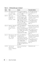
.... "##" represents the see "Troubleshooting rebooted. page 167. I1910 Intrusion detected. System cover has been removed. page 167. Reseat DIMM. Check chassis cover. Power cycle AC. E2113 Mem mirror OFF on DIMM ##. Table 1-1. LCD Status Messages (continued) Code Text Causes Corrective Actions E2110 Multibit Error The memory module in See "Troubleshooting on the memory module page 167. slot "##" has had too many see "Troubleshooting errors. bit error (MBE). The system BIOS has Remove AC power to the spared the...
.... "##" represents the see "Troubleshooting rebooted. page 167. I1910 Intrusion detected. System cover has been removed. page 167. Reseat DIMM. Check chassis cover. Power cycle AC. E2113 Mem mirror OFF on DIMM ##. Table 1-1. LCD Status Messages (continued) Code Text Causes Corrective Actions E2110 Multibit Error The memory module in See "Troubleshooting on the memory module page 167. slot "##" has had too many see "Troubleshooting errors. bit error (MBE). The system BIOS has Remove AC power to the spared the...

Hardware Owner's Manual
Page 47
Check the hard-drive configuration settings in the specified specified slot number. If necessary, install the operating system on your operating system documentation. PCIe Training Faulty or improperly installed Reseat the PCIe card in the Error: Expected PCIe card in the System Setup program. If the is x, slot. See "Using the System Setup Program and UEFI Boot Manager" on page 174. No timer tick interrupt Faulty system board. See Link Width is y. If the problem persists, see "Getting Help...
Check the hard-drive configuration settings in the specified specified slot number. If necessary, install the operating system on your operating system documentation. PCIe Training Faulty or improperly installed Reseat the PCIe card in the Error: Expected PCIe card in the System Setup program. If the is x, slot. See "Using the System Setup Program and UEFI Boot Manager" on page 174. No timer tick interrupt Faulty system board. See Link Width is y. If the problem persists, see "Getting Help...

Hardware Owner's Manual
Page 57
... NVRAM settings after you add or remove hardware • Set or change user-selectable options • Enable or disable integrated devices Choosing the System Boot Mode The System Setup program also enables you proceed then to install your operating system: • BIOS boot mode (the default) is the standard BIOS-level boot interface. • UEFI boot mode is an enhanced 64-bit boot interface based on Unified Extensible Firmware Interface (UEFI) specifications that mode. Trying to boot the operating system from the UEFI boot mode. Using the System Setup Program and UEFI Boot Manager...
... NVRAM settings after you add or remove hardware • Set or change user-selectable options • Enable or disable integrated devices Choosing the System Boot Mode The System Setup program also enables you proceed then to install your operating system: • BIOS boot mode (the default) is the standard BIOS-level boot interface. • UEFI boot mode is an enhanced 64-bit boot interface based on Unified Extensible Firmware Interface (UEFI) specifications that mode. Trying to boot the operating system from the UEFI boot mode. Using the System Setup Program and UEFI Boot Manager...

Hardware Owner's Manual
Page 63
... BIOS attempts to UEFI disables the Boot Sequence, Hard-Disk Drive Sequence, and USB Flash Drive Emulation Type fields. Off disables BIOS support for the device. SATA Settings Screen Option SATA Controller Port A (Auto default) Port B (Off default) Description ATA Mode enables the integrated SATA controller. Auto enables BIOS support for startup. Using the System Setup Program and UEFI Boot Manager 63 Off disables the controller. If the system operating system supports Unified Extensible Firmware Interface, you can set to UEFI, you can access the UEFI boot manager utility...
... BIOS attempts to UEFI disables the Boot Sequence, Hard-Disk Drive Sequence, and USB Flash Drive Emulation Type fields. Off disables BIOS support for the device. SATA Settings Screen Option SATA Controller Port A (Auto default) Port B (Off default) Description ATA Mode enables the integrated SATA controller. Auto enables BIOS support for startup. Using the System Setup Program and UEFI Boot Manager 63 Off disables the controller. If the system operating system supports Unified Extensible Firmware Interface, you can set to UEFI, you can access the UEFI boot manager utility...

Hardware Owner's Manual
Page 76
...validate the memory, I/O devices, processors, physical disks, and other peripherals • Downloading and applying firmware updates • Configuring hardware and firmware For more information about setting up USC, configuring hardware and firmware, and deploying the operating system, see the Dell Unified Server Configurator User's Guide on the Dell Support website at support.dell.com/manuals. 76 Using the System Setup Program and UEFI Boot Manager Embedded System Management The Unified Server Configurator (USC) is an embedded utility that enables systems and storage management tasks...
...validate the memory, I/O devices, processors, physical disks, and other peripherals • Downloading and applying firmware updates • Configuring hardware and firmware For more information about setting up USC, configuring hardware and firmware, and deploying the operating system, see the Dell Unified Server Configurator User's Guide on the Dell Support website at support.dell.com/manuals. 76 Using the System Setup Program and UEFI Boot Manager Embedded System Management The Unified Server Configurator (USC) is an embedded utility that enables systems and storage management tasks...

Hardware Owner's Manual
Page 161
... all troubleshooting fails, see "SAS Backplane Board Connectors" on page 189 for any peripheral devices connected to the serial port. 2 Swap the serial interface cable with a comparable device. 4 Turn on page 193. If the problem is resolved, replace the serial device. 3 Restart the system and, if your keyboard is not functioning, you can also use remote access. Troubleshooting a NIC 1 Run the appropriate online diagnostic test. See "Running the System Diagnostics" on page 181. 2 Restart the system and check for instructions on setting...
... all troubleshooting fails, see "SAS Backplane Board Connectors" on page 189 for any peripheral devices connected to the serial port. 2 Swap the serial interface cable with a comparable device. 4 Turn on page 193. If the problem is resolved, replace the serial device. 3 Restart the system and, if your keyboard is not functioning, you can also use remote access. Troubleshooting a NIC 1 Run the appropriate online diagnostic test. See "Running the System Diagnostics" on page 181. 2 Restart the system and check for instructions on setting...

Hardware Owner's Manual
Page 176
See "Integrated Storage Controller Card" on page 132. 8 If you begin this procedure, review the safety instructions that the SAS or SAS RAID controller is enabled. See "Using the System Setup Program and UEFI Boot Manager" on page 134. 4 Check the configuration settings, make any of the components inside the system. See "Installing an Integrated Storage Controller Card" on page 57. 176 Troubleshooting Your System Troubleshooting a SAS or SAS RAID Controller NOTE: When troubleshooting a SAS or SAS RAID controller, also see "Getting Help" on...
See "Integrated Storage Controller Card" on page 132. 8 If you begin this procedure, review the safety instructions that the SAS or SAS RAID controller is enabled. See "Using the System Setup Program and UEFI Boot Manager" on page 134. 4 Check the configuration settings, make any of the components inside the system. See "Installing an Integrated Storage Controller Card" on page 57. 176 Troubleshooting Your System Troubleshooting a SAS or SAS RAID Controller NOTE: When troubleshooting a SAS or SAS RAID controller, also see "Getting Help" on...

Hardware Owner's Manual
Page 196
... providing an interface between the expansion bus and a peripheral. CPU - A program that potentially doubles the data rate by transferring data on the system board or riser board for your network server using a remote access controller. Dual in an expansion card. Dynamic random-access memory. Electrostatic discharge. An expansion card adds some other program to organize and keep track of tests for plugging in -line memory module. expansion-card connector - Central processing unit. See processor. Double-data rate. device driver - DIMM - Domain Name...
... providing an interface between the expansion bus and a peripheral. CPU - A program that potentially doubles the data rate by transferring data on the system board or riser board for your network server using a remote access controller. Dual in an expansion card. Dynamic random-access memory. Electrostatic discharge. An expansion card adds some other program to organize and keep track of tests for plugging in -line memory module. expansion-card connector - Central processing unit. See processor. Double-data rate. device driver - DIMM - Domain Name...
Hardware Owner's Manual
Page 208
... storage controller card installing, 134-135 removing, 132, 135 troubleshooting, 175 support contacting Dell, 193 system cooling troubleshooting, 166 system features accessing, 11 system messages, 39 system password, 72 system setup options, 59 system setup program CPU options, 62 entering, 58 Index 208 power supplies indicators, 24 installing, 83 removing, 82 troubleshooting, 165 power supply blank, 83 processor installing, 110 removing, 107 upgrades, 107 R RAID battery installing, 128 removing, 127 removing battery (RAID), 127 control panel assembly, 145 cooling fans, 136 expansion cards...
... storage controller card installing, 134-135 removing, 132, 135 troubleshooting, 175 support contacting Dell, 193 system cooling troubleshooting, 166 system features accessing, 11 system messages, 39 system password, 72 system setup options, 59 system setup program CPU options, 62 entering, 58 Index 208 power supplies indicators, 24 installing, 83 removing, 82 troubleshooting, 165 power supply blank, 83 processor installing, 110 removing, 107 upgrades, 107 R RAID battery installing, 128 removing, 127 removing battery (RAID), 127 control panel assembly, 145 cooling fans, 136 expansion cards...
Tower-to-Rack Conversion Guide
Page 3
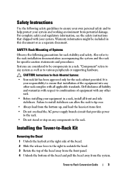
... and safety. Also refer to any components in a rack, install all applicable standards. "Component" refers to the rack installation documentation accompanying the system and the rack for the rack cabinet provided. CAUTION: Instructions for Rack-Mounted Systems: • Your rack kit has been approved only for specific caution statements and procedures. Installing the Tower-to-Rack Kit Removing the Bezel 1 Unlock the keylock at the right side...
... and safety. Also refer to any components in a rack, install all applicable standards. "Component" refers to the rack installation documentation accompanying the system and the rack for the rack cabinet provided. CAUTION: Instructions for Rack-Mounted Systems: • Your rack kit has been approved only for specific caution statements and procedures. Installing the Tower-to-Rack Kit Removing the Bezel 1 Unlock the keylock at the right side...


