
Glossary
Page 8
... tells a system what hardware is running. TCP/IP - termination - uplink port - A battery-powered unit that allows a network manager to other hubs or switches without requiring a crossover cable. Simple Network Management Protocol. The amount of an electrical failure. TOE - A ...access to your system's integral components, such as mice and keyboards. An unregistered (unbuffered) DDR3 memory module. Uninterruptible power supply. A USB connector provides a single connection point for video adapters with greater resolution and color display capabilities than ...
... tells a system what hardware is running. TCP/IP - termination - uplink port - A battery-powered unit that allows a network manager to other hubs or switches without requiring a crossover cable. Simple Network Management Protocol. The amount of an electrical failure. TOE - A ...access to your system's integral components, such as mice and keyboards. An unregistered (unbuffered) DDR3 memory module. Uninterruptible power supply. A USB connector provides a single connection point for video adapters with greater resolution and color display capabilities than ...

Information Update - Power Infrastructure Sizing
Page 1
... at 1000W and the characterization results in a significantly different power consumption requirement than 50 percent. Combined use of Power Distribution Units (PDUs), Uninterruptible Power Supplies (UPSs), and other power infrastructure distribution equipment. Systems characterized while using the power capping features enabled from Dell may result in 500W of power consumption for a specific deployment, the assessment may help to...
... at 1000W and the characterization results in a significantly different power consumption requirement than 50 percent. Combined use of Power Distribution Units (PDUs), Uninterruptible Power Supplies (UPSs), and other power infrastructure distribution equipment. Systems characterized while using the power capping features enabled from Dell may result in 500W of power consumption for a specific deployment, the assessment may help to...

Information Update
Page 4
...Address Labels For security reasons, the embedded NIC and iDRAC6 Enterprise MAC address labels provided with the 10 Gb I/O riser: • To ensure system power redundancy, the 10 Gb I /O riser provides two 10 Gb SFP+ ports using a Broadcom® 57711 controller in the boot.ini file before...the system. System Limitations With an Optional 10 Gb I/O Riser The 10 Gb I /O riser requires all four power supplies to be affixed after the system power becomes non-redundant can lead to the AC power source. After installing the operating system, add a boot time switch mem=1046528 or /burnmemory=...
...Address Labels For security reasons, the embedded NIC and iDRAC6 Enterprise MAC address labels provided with the 10 Gb I/O riser: • To ensure system power redundancy, the 10 Gb I /O riser provides two 10 Gb SFP+ ports using a Broadcom® 57711 controller in the boot.ini file before...the system. System Limitations With an Optional 10 Gb I/O Riser The 10 Gb I /O riser requires all four power supplies to be affixed after the system power becomes non-redundant can lead to the AC power source. After installing the operating system, add a boot time switch mem=1046528 or /burnmemory=...
Hardware Owner's Manual
Page 30
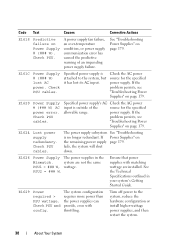
... are not the same PSU1 = ### W, wattage. Check PSU. E1629 Power The system configuration required > requires more power than PSU wattage. A power supply fan failure, an over-temperature condition, or power supply communication error has caused the predictive warning of the source for the specified power supply. Specified power supply is attached to the system, reduce the hardware configuration...
... are not the same PSU1 = ### W, wattage. Check PSU. E1629 Power The system configuration required > requires more power than PSU wattage. A power supply fan failure, an over-temperature condition, or power supply communication error has caused the predictive warning of the source for the specified power supply. Specified power supply is attached to the system, reduce the hardware configuration...
Hardware Owner's Manual
Page 40
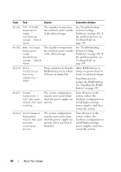
... System Cooling Problems" on page 180. Turn off power to the system, reduce the hardware configuration or install higher-wattage power supplies, and then restart the system. The system configuration requires more power than what the power supply can boot if throttled. W1627 Power The system configuration required > requires more power than PSU wattage. W1102 Mem Voltage Regulator temp...
... System Cooling Problems" on page 180. Turn off power to the system, reduce the hardware configuration or install higher-wattage power supplies, and then restart the system. The system configuration requires more power than what the power supply can boot if throttled. W1627 Power The system configuration required > requires more power than PSU wattage. W1102 Mem Voltage Regulator temp...

Hardware Owner's Manual
Page 42
...the problem persists, see "General Memory Module Installation Guidelines" on page 181. 42 About Your System Memory configuration does not support Node Interleaving. Power required may power down without node interleaving. Alert! Continuing system boot accepts the risk that system may exceed PSU wattage. Node Interleaving disabled! Check other system ...booting After AC recovery, the iDRAC6 takes longer than normal to the system for 10 seconds and restart the system. Remove AC power to boot. iDRAC6 not responding. The system will run but without warning. The iDRAC6 is hung.
...the problem persists, see "General Memory Module Installation Guidelines" on page 181. 42 About Your System Memory configuration does not support Node Interleaving. Power required may power down without node interleaving. Alert! Continuing system boot accepts the risk that system may exceed PSU wattage. Node Interleaving disabled! Check other system ...booting After AC recovery, the iDRAC6 takes longer than normal to the system for 10 seconds and restart the system. Remove AC power to boot. iDRAC6 not responding. The system will run but without warning. The iDRAC6 is hung.

Hardware Owner's Manual
Page 43
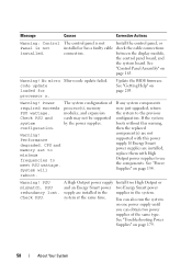
... See "Using the System Setup Program and UEFI Boot Manager" on page 181. messages for additional information for normal operation. Power required exceeds PSU wattage. Check PSU and system configuration. The system configuration of manufacturing mode. Redundant memory disabled! Alert! BIOS MANUFACTURING... accepts the risk that system may not be supported by the power supplies. Memory configuration does not support redundant memory. See "Troubleshooting System Memory" on page 63. System reboot required for possible causes. If any system components were just upgraded, ...
... See "Using the System Setup Program and UEFI Boot Manager" on page 181. messages for additional information for normal operation. Power required exceeds PSU wattage. Check PSU and system configuration. The system configuration of manufacturing mode. Redundant memory disabled! Alert! BIOS MANUFACTURING... accepts the risk that system may not be supported by the power supplies. Memory configuration does not support redundant memory. See "Troubleshooting System Memory" on page 63. System reboot required for possible causes. If any system components were just upgraded, ...
Hardware Owner's Manual
Page 58
... Check PSU. system at the same time. The control panel is not installed. code update loaded for processor n. Power required exceeds PSU wattage. If any system components were just upgraded, return the system to meet PSU wattage. PSU redundancy lost. A High ...(s) are installed in the supplies in the system. Warning! Warning! Check PSU and system configuration. If the system boots without this power supply. PSU mismatch. between the display module, the control panel board, and the system board. Warning! Message Causes Corrective Actions Warning...
... Check PSU. system at the same time. The control panel is not installed. code update loaded for processor n. Power required exceeds PSU wattage. If any system components were just upgraded, return the system to meet PSU wattage. PSU redundancy lost. A High ...(s) are installed in the supplies in the system. Warning! Warning! Check PSU and system configuration. If the system boots without this power supply. PSU mismatch. between the display module, the control panel board, and the system board. Warning! Message Causes Corrective Actions Warning...
Hardware Owner's Manual
Page 60
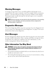
... interrupt the task and require you to install your system into a rack. • The Getting Started Guide provides an overview of system features, setting up your system, and technical specifications. 60 About Your System See "Running the System Diagnostics" on page 193 for drive, temperature, fan, and power conditions. Other Information You...
... interrupt the task and require you to install your system into a rack. • The Getting Started Guide provides an overview of system features, setting up your system, and technical specifications. 60 About Your System See "Running the System Diagnostics" on page 193 for drive, temperature, fan, and power conditions. Other Information You...
Hardware Owner's Manual
Page 66
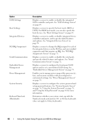
... the processor(s), fans, and memory modules with the NumLock mode activated on the PCI bus, and any installed expansion card that requires an IRQ. Enables you can also specify the boot devices. Determines whether your system starts up with preconfigured or customized settings. See...defined LCD string. See "Integrated Devices Screen" on page 73. Displays a screen to configure the system password and setup password features. See "Power Management Screen" on page 70. Displays a screen to enable or disable the serial ports and specify related features and options. Displays a screen...
... the processor(s), fans, and memory modules with the NumLock mode activated on the PCI bus, and any installed expansion card that requires an IRQ. Enables you can also specify the boot devices. Determines whether your system starts up with preconfigured or customized settings. See...defined LCD string. See "Integrated Devices Screen" on page 73. Displays a screen to configure the system password and setup password features. See "Power Management Screen" on page 70. Displays a screen to enable or disable the serial ports and specify related features and options. Displays a screen...
Hardware Owner's Manual
Page 71
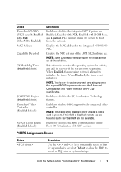
... with operating systems that support WDAT implementations of an additional driver. If this field is not initialized. NOTE: Some LOM features may require the installation of the Advanced Configuration and Power Interface (ACPI) 3.0b specification. When Disabled, the timer is disabled, remote access features such as virtual KVM are Enabled, Enabled with...
... with operating systems that support WDAT implementations of an additional driver. If this field is not initialized. NOTE: Some LOM features may require the installation of the Advanced Configuration and Power Interface (ACPI) 3.0b specification. When Disabled, the timer is disabled, remote access features such as virtual KVM are Enabled, Enabled with...

Hardware Owner's Manual
Page 154
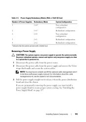
... Non-redundant configuration Redundant configuration 154 Installing System Components The system requires two power supplies to provide standby power to the system. System Configuration Non-redundant configuration with a limited load. Table 3-4. Power Supply Redundancy Modes With a 10 Gb I /O card is required to provide standby power to the system. See "Closing the System" on page 90. 19...
... Non-redundant configuration Redundant configuration 154 Installing System Components The system requires two power supplies to provide standby power to the system. System Configuration Non-redundant configuration with a limited load. Table 3-4. Power Supply Redundancy Modes With a 10 Gb I /O card is required to provide standby power to the system. See "Closing the System" on page 90. 19...
Hardware Owner's Manual
Page 155
... load. Installing System Components 155 Table 3-5. System Configuration Non-redundant configuration Redundant configuration Non-redundant configuration Redundant configuration Redundant configuration Removing a Power Supply CAUTION: The system requires one power supply at a time in a system that is powered on page 157. For information about the cable management arm, see the system's rack documentation. 3 Pull the...
... load. Installing System Components 155 Table 3-5. System Configuration Non-redundant configuration Redundant configuration Non-redundant configuration Redundant configuration Redundant configuration Removing a Power Supply CAUTION: The system requires one power supply at a time in a system that is powered on page 157. For information about the cable management arm, see the system's rack documentation. 3 Pull the...
Hardware Owner's Manual
Page 180
... warranty. Damage due to servicing that none of the following conditions exist: • System cover, drive blank, memory-module blank, power-supply blank, or back filler bracket is removed. • Ambient temperature is on page 89. To maintain proper cooling while the ... or the diagnostic software 180 Troubleshooting Your System Read and follow the safety instructions that is not authorized by Dell is not covered by your system's operating temperature requirements. • External airflow is obstructed. • Cables inside the system obstruct airflow. • An individual...
... warranty. Damage due to servicing that none of the following conditions exist: • System cover, drive blank, memory-module blank, power-supply blank, or back filler bracket is removed. • Ambient temperature is on page 89. To maintain proper cooling while the ... or the diagnostic software 180 Troubleshooting Your System Read and follow the safety instructions that is not authorized by Dell is not covered by your system's operating temperature requirements. • External airflow is obstructed. • Cables inside the system obstruct airflow. • An individual...


