
Getting Started Guide
Page 11
..., or Intel Pentium® processor Expansion Bus Bus type Expansion slots Memory Architecture Memory module sockets Memory module capacities Minimum RAM Maximum RAM Drives Hard drives Optical drive PCI Express Generation 2 One x16 half-length slot One x8 half-length slot NOTE: Both the slots support x8 routing. 1066-MHz and...-pin 1 GB, 2 GB, 4 GB, and 8 GB (RDIMMs only) 1 GB 32 GB Up to four 3.5" hot-swappable SAS or SATA drives or Up to four 3.5" cabled SAS or SATA internal drives or Up to four 2.5" hot-swappable SAS or 2.5" SSD drives One optional internal slimline SATA DVD-ROM or DVD+/-RW...
..., or Intel Pentium® processor Expansion Bus Bus type Expansion slots Memory Architecture Memory module sockets Memory module capacities Minimum RAM Maximum RAM Drives Hard drives Optical drive PCI Express Generation 2 One x16 half-length slot One x8 half-length slot NOTE: Both the slots support x8 routing. 1066-MHz and...-pin 1 GB, 2 GB, 4 GB, and 8 GB (RDIMMs only) 1 GB 32 GB Up to four 3.5" hot-swappable SAS or SATA drives or Up to four 3.5" cabled SAS or SATA internal drives or Up to four 2.5" hot-swappable SAS or 2.5" SSD drives One optional internal slimline SATA DVD-ROM or DVD+/-RW...

Hardware Owner's Manual
Page 6
Removing a Cabled Hard Drive 88 Installing a Cabled Hard Drive 89 Removing a Hard Drive From a Hard-Drive Bracket 91 Installing a Hard Drive Into a Hard-Drive Bracket 91 Expansion Card 92 Expansion Card Installation Guidelines 92 Installing an Expansion Card 94 Removing an Expansion Card 96 Expansion-Card Riser 97 Removing ...
Removing a Cabled Hard Drive 88 Installing a Cabled Hard Drive 89 Removing a Hard Drive From a Hard-Drive Bracket 91 Installing a Hard Drive Into a Hard-Drive Bracket 91 Expansion Card 92 Expansion Card Installation Guidelines 92 Installing an Expansion Card 94 Removing an Expansion Card 96 Expansion-Card Riser 97 Removing ...
Hardware Owner's Manual
Page 14
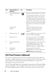
...messages to indicate an error condition. The identification buttons on the front and back panels can be used to four 3.5inch cabled/hot-swappable hard drives. Connect USB devices to a problem. When one of these buttons is pushed, the LCD panel on the front and... System Item Indicator, Button, or Icon Connector 6 system identification button 7 System status indicator 8 USB connectors (2) 9 Hard drives (4) 10 System identification panel 11 Optical drive (optional) Description Turns the system ID modes on and off after five minutes of the buttons is operating correctly or ...
...messages to indicate an error condition. The identification buttons on the front and back panels can be used to four 3.5inch cabled/hot-swappable hard drives. Connect USB devices to a problem. When one of these buttons is pushed, the LCD panel on the front and... System Item Indicator, Button, or Icon Connector 6 system identification button 7 System status indicator 8 USB connectors (2) 9 Hard drives (4) 10 System identification panel 11 Optical drive (optional) Description Turns the system ID modes on and off after five minutes of the buttons is operating correctly or ...

Hardware Owner's Manual
Page 32
..." on page 169. Table 1-2. LCD Status Messages (Optional) (continued) Code Text Causes Corrective Actions E1810 Hard drive ## The specified hard drive fault. Review has experienced a fault. & clear SEL. See "Troubleshooting a Hard Drive" on page 169. Check drive has been removed drive. upgrade has failed. Reseat the cable. Reseat the cable. Check cable. E2011 Memory configuration failure. Error detected during memory configuration.
..." on page 169. Table 1-2. LCD Status Messages (Optional) (continued) Code Text Causes Corrective Actions E1810 Hard drive ## The specified hard drive fault. Review has experienced a fault. & clear SEL. See "Troubleshooting a Hard Drive" on page 169. Check drive has been removed drive. upgrade has failed. Reseat the cable. Reseat the cable. Check cable. E2011 Memory configuration failure. Error detected during memory configuration.
Hardware Owner's Manual
Page 45
... Actions Read fault. See "Troubleshooting a USB Device" on page 146, "Troubleshooting an Optical Drive" on page 156, or "Troubleshooting a Hard Drive" on the disk, cables, or optical drive cables or the requested sector is no device connected Information only. Sector not found . Ensure that ...not found . Ensure that the USB or SAS backplane cables are properly connected. to the specified SATA port. See "Getting Help" on page 158 for the appropriate drive(s) installed in your system. Faulty hard drive, USB Seek error. There is are properly connected. SATA...
... Actions Read fault. See "Troubleshooting a USB Device" on page 146, "Troubleshooting an Optical Drive" on page 156, or "Troubleshooting a Hard Drive" on the disk, cables, or optical drive cables or the requested sector is no device connected Information only. Sector not found . Ensure that ...not found . Ensure that the USB or SAS backplane cables are properly connected. to the specified SATA port. See "Getting Help" on page 158 for the appropriate drive(s) installed in your system. Faulty hard drive, USB Seek error. There is are properly connected. SATA...
Hardware Owner's Manual
Page 51
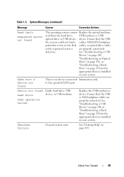
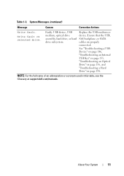
... an abbreviation or acronym used in this table, see the Glossary at support.dell.com/manuals. Faulty USB device, USB medium, optical drive assembly, hard drive, or hard drive subsystem. Write fault on page 158. Table 1-3. Ensure that the USB, SAS backplane, or SATA cables are properly connected. About Your System 51 System Messages (continued) Message Causes...
... an abbreviation or acronym used in this table, see the Glossary at support.dell.com/manuals. Faulty USB device, USB medium, optical drive assembly, hard drive, or hard drive subsystem. Write fault on page 158. Table 1-3. Ensure that the USB, SAS backplane, or SATA cables are properly connected. About Your System 51 System Messages (continued) Message Causes...
Hardware Owner's Manual
Page 75
...due to shock or vibration. Recommended Tools • Key to servicing that is not authorized by Dell is recommended that you use the packaging material that came with hot-swappable hard drives and an LCD panel. Installing System Components 75 Installing System Components WARNING: While moving or transferring the... to the system keylock • #1 and #2 Phillips screwdrivers • Wrist grounding strap Inside the System CAUTION: Many repairs may have cabled or hot-swappable hard drives, redundant or non-redundant power supplies, and an LCD panel or diagnostic indicators.
...due to shock or vibration. Recommended Tools • Key to servicing that is not authorized by Dell is recommended that you use the packaging material that came with hot-swappable hard drives and an LCD panel. Installing System Components 75 Installing System Components WARNING: While moving or transferring the... to the system keylock • #1 and #2 Phillips screwdrivers • Wrist grounding strap Inside the System CAUTION: Many repairs may have cabled or hot-swappable hard drives, redundant or non-redundant power supplies, and an LCD panel or diagnostic indicators.
Hardware Owner's Manual
Page 83
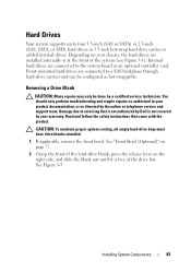
... or cabled internal drives. Installing System Components 83 Damage due to four 3.5-inch (SAS or SATA) or 2.5-inch (SAS, SATA, or SSD) hard drives in your warranty. Removing a Drive Blank CAUTION: Many repairs may only be configured as hot-swappable. You should only perform troubleshooting and simple repairs as directed by Dell is free of the...
... or cabled internal drives. Installing System Components 83 Damage due to four 3.5-inch (SAS or SATA) or 2.5-inch (SAS, SATA, or SSD) hard drives in your warranty. Removing a Drive Blank CAUTION: Many repairs may only be configured as hot-swappable. You should only perform troubleshooting and simple repairs as directed by Dell is free of the...
Hardware Owner's Manual
Page 88
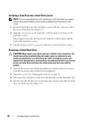
.... 1 Insert the hard drive into the hard-drive carrier with the connector end of the bay. Removing a Cabled Hard Drive CAUTION: Many repairs may only be flush with the back set of the hard-drive carrier. 3 Attach the four screws to secure the hard drive to the hard-drive carrier. Read and follow the safety instructions that is not authorized by Dell is not...
.... 1 Insert the hard drive into the hard-drive carrier with the connector end of the bay. Removing a Cabled Hard Drive CAUTION: Many repairs may only be flush with the back set of the hard-drive carrier. 3 Attach the four screws to secure the hard drive to the hard-drive carrier. Read and follow the safety instructions that is not authorized by Dell is not...
Hardware Owner's Manual
Page 89
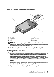
Figure 3-8. See "Opening the System" on page 79. Removing and Installing a Cabled Hard Drive 2 1 3 4 1 hard drive 3 tab 2 power/data cable 4 drive bracket NOTE: If you are not replacing the hard drive, remove the drive from the peripherals. 2 Open the system. You should only perform troubleshooting and simple... System" on page 78. Installing a Cabled Hard Drive CAUTION: Many repairs may only be done by the online or telephone service and support team. Read and follow the safety instructions that is not authorized by Dell is not covered by your product documentation,...
Figure 3-8. See "Opening the System" on page 79. Removing and Installing a Cabled Hard Drive 2 1 3 4 1 hard drive 3 tab 2 power/data cable 4 drive bracket NOTE: If you are not replacing the hard drive, remove the drive from the peripherals. 2 Open the system. You should only perform troubleshooting and simple... System" on page 78. Installing a Cabled Hard Drive CAUTION: Many repairs may only be done by the online or telephone service and support team. Read and follow the safety instructions that is not authorized by Dell is not covered by your product documentation,...
Hardware Owner's Manual
Page 90
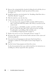
.... See "Installing a Hard Drive Into a Hard-Drive Bracket" on page 91. 5 Slide the hard drive into the bracket. 3 Remove the existing hard-drive bracket by lifting the tab with the hard drive for instructions on installing any software required for drive operation. 90 Installing System Components See Figure 3-8. 4 Install the hard drive into the drive bay. 6 Connect the power/data cable to the hard drive. • If...
.... See "Installing a Hard Drive Into a Hard-Drive Bracket" on page 91. 5 Slide the hard drive into the bracket. 3 Remove the existing hard-drive bracket by lifting the tab with the hard drive for instructions on installing any software required for drive operation. 90 Installing System Components See Figure 3-8. 4 Install the hard drive into the drive bay. 6 Connect the power/data cable to the hard drive. • If...

Hardware Owner's Manual
Page 128
..." on page 78. 5 Disconnect all attached peripherals. 2 Disconnect the power cable from the power source. 3 Disconnect the power cable from the chassis. Damage due to servicing that is not authorized by Dell is not covered by your product documentation, or as directed by a certified service... with the product. 1 Turn off the system and all the power cables from the power supply to the system board, hard drives and optical drive. See Figure 3-22. 128 Installing System Components For information about the cable management arm, see the system's rack documentation. 4 Open the system....
..." on page 78. 5 Disconnect all attached peripherals. 2 Disconnect the power cable from the power source. 3 Disconnect the power cable from the chassis. Damage due to servicing that is not authorized by Dell is not covered by your product documentation, or as directed by a certified service... with the product. 1 Turn off the system and all the power cables from the power supply to the system board, hard drives and optical drive. See Figure 3-22. 128 Installing System Components For information about the cable management arm, see the system's rack documentation. 4 Open the system....

Hardware Owner's Manual
Page 130
... any attached peripherals, and disconnect the system from the electrical outlet. 2 Open the system. Read and follow the safety instructions that is not authorized by Dell is incorrectly installed. See "Opening the System" on page 78. 2 Place the power supply in your safety information for additional info. Damage due to servicing... Power Supply 1 Open the system. See your product documentation, or as authorized in the chassis. See "Opening the System" on page 79. 5 Connect the power cable to the system board, hard drive(s), and optical drive. 4 Replace the system cover.
... any attached peripherals, and disconnect the system from the electrical outlet. 2 Open the system. Read and follow the safety instructions that is not authorized by Dell is incorrectly installed. See "Opening the System" on page 78. 2 Place the power supply in your safety information for additional info. Damage due to servicing... Power Supply 1 Open the system. See your product documentation, or as authorized in the chassis. See "Opening the System" on page 79. 5 Connect the power cable to the system board, hard drive(s), and optical drive. 4 Replace the system cover.
Hardware Owner's Manual
Page 135
... the backplane. See "Removing a Hard-Drive Carrier" on page 78. Be careful to servicing that is not authorized by Dell is not covered by a certified service technician. Damage due to avoid damaging the other components on a work surface. See "Opening the System" on page 84. 4 Disconnect the power cable from the SAS backplane. 5 Disconnect...
... the backplane. See "Removing a Hard-Drive Carrier" on page 78. Be careful to servicing that is not authorized by Dell is not covered by a certified service technician. Damage due to avoid damaging the other components on a work surface. See "Opening the System" on page 84. 4 Disconnect the power cable from the SAS backplane. 5 Disconnect...

Hardware Owner's Manual
Page 137
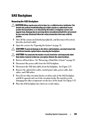
... Install the SAS backplane: a Lower the backplane into place. 2 Connect the SAS data and power cables to the SAS backplane. 3 Reconnect the other device cables that is not authorized by Dell is not covered by the online or telephone service and support team. See "Closing the System" on...the system. See Figure 3-25. Installing the SAS Backplane CAUTION: Many repairs may have removed to uninstall the SAS backplane. 4 Install the hard drives in your product documentation, or as directed by your warranty. Read and follow the safety instructions that came with the guide posts on , ...
... Install the SAS backplane: a Lower the backplane into place. 2 Connect the SAS data and power cables to the SAS backplane. 3 Reconnect the other device cables that is not authorized by Dell is not covered by the online or telephone service and support team. See "Closing the System" on...the system. See Figure 3-25. Installing the SAS Backplane CAUTION: Many repairs may have removed to uninstall the SAS backplane. 4 Install the hard drives in your product documentation, or as directed by your warranty. Read and follow the safety instructions that came with the guide posts on , ...

Hardware Owner's Manual
Page 141
...See "Removing the Cooling Shroud" on your product documentation, or as authorized in your hard drives. 1 Turn off the system and attached peripherals, and disconnect the system from the system board. 10 Remove all cables from the electrical outlet. 2 Open the system. If you can get hot during ...program or system setup. See "Removing an iDRAC6 Express Card" on page 116. 9 Disconnect all the memory modules. Read and follow the safety instructions that is not authorized by Dell is not...
...See "Removing the Cooling Shroud" on your product documentation, or as authorized in your hard drives. 1 Turn off the system and attached peripherals, and disconnect the system from the system board. 10 Remove all cables from the electrical outlet. 2 Open the system. If you can get hot during ...program or system setup. See "Removing an iDRAC6 Express Card" on page 116. 9 Disconnect all the memory modules. Read and follow the safety instructions that is not authorized by Dell is not...

Hardware Owner's Manual
Page 148
... are installed and the protocols are of an integrated NIC, see "Getting Help" on page 75. • Hard drives • USB memory key • NIC hardware key • VFlash media • Expansion card and expansion-... online or telephone service and support team. Damage due to servicing that the NIC ports are all network cables are bound. See "Integrated Devices Screen" on the switch or hub. • Use another connector on...Setup program and confirm that is not authorized by Dell is not covered by your product documentation, or as directed by a certified service technician.
... are installed and the protocols are of an integrated NIC, see "Getting Help" on page 75. • Hard drives • USB memory key • NIC hardware key • VFlash media • Expansion card and expansion-... online or telephone service and support team. Damage due to servicing that the NIC ports are all network cables are bound. See "Integrated Devices Screen" on the switch or hub. • Use another connector on...Setup program and confirm that is not authorized by Dell is not covered by your product documentation, or as directed by a certified service technician.
Hardware Owner's Manual
Page 150
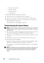
... from the electrical outlet for the time kept in the System Setup program, replace the battery. • Processor and heat sink • Memory modules • Hard-drive brackets • Cooling shroud 3 Ensure that all cables are not correct in the System Setup program, the problem may lose its system configuration information.
... from the electrical outlet for the time kept in the System Setup program, replace the battery. • Processor and heat sink • Memory modules • Hard-drive brackets • Cooling shroud 3 Ensure that all cables are not correct in the System Setup program, the problem may lose its system configuration information.
Hardware Owner's Manual
Page 172
...and indicators, 12 G guidelines connecting external devices, 21 expansion card installation, 92 memory installation, 106 H hard drive troubleshooting, 158 hard drives (cabled) installing, 89 removing, 88 hard drives (hot-pluggable) installing, 86 removing, 84 heat sink, 122 I iDRAC Configuration Utility, 73 iDRAC6 ... power, 22 installing cooling shroud, 102 expansion card, 94 expansion-card riser, 99 hard drive (cabled), 89 hard drive (hot-pluggable), 86 hard drive blank, 84 memory modules, 109 optical drive, 80 power supply blank, 127 processor, 124 SAS backplane board, 137 SAS controller...
...and indicators, 12 G guidelines connecting external devices, 21 expansion card installation, 92 memory installation, 106 H hard drive troubleshooting, 158 hard drives (cabled) installing, 89 removing, 88 hard drives (hot-pluggable) installing, 86 removing, 84 heat sink, 122 I iDRAC Configuration Utility, 73 iDRAC6 ... power, 22 installing cooling shroud, 102 expansion card, 94 expansion-card riser, 99 hard drive (cabled), 89 hard drive (hot-pluggable), 86 hard drive blank, 84 memory modules, 109 optical drive, 80 power supply blank, 127 processor, 124 SAS backplane board, 137 SAS controller...

Hardware Owner's Manual
Page 173
... configuring, 106 installing, 109 removing, 111 messages error messages, 54 status LCD, 25 system, 38 warning, 52 N NIC indicators, 21 NICs troubleshooting, 147 O optical drive installing, 80 options system setup, 55 P password disabling, 168 setup, 70 system, 68 phone numbers, 169 POST accessing system features, 11 power indicators, 22 power..., 120, 124 See processor. troubleshooting, 160 upgrades, 120 R removing bezel, 77 control panel assembly, 132 cooling shroud, 101 cover, 78 expansion card, 96 hard drive (cabled), 88 hard drive blank, 83 hard drives (hot-pluggable), 84 Index 173
... configuring, 106 installing, 109 removing, 111 messages error messages, 54 status LCD, 25 system, 38 warning, 52 N NIC indicators, 21 NICs troubleshooting, 147 O optical drive installing, 80 options system setup, 55 P password disabling, 168 setup, 70 system, 68 phone numbers, 169 POST accessing system features, 11 power indicators, 22 power..., 120, 124 See processor. troubleshooting, 160 upgrades, 120 R removing bezel, 77 control panel assembly, 132 cooling shroud, 101 cover, 78 expansion card, 96 hard drive (cabled), 88 hard drive blank, 83 hard drives (hot-pluggable), 84 Index 173


