
Glossary
Page 6
... In RAID arrays, a striped hard drive containing parity data. PowerEdge RAID controller. A single point on self-test. Power-on a video display. processor - Preboot eXecution Environment. ns - Nanosecond(s). NVRAM - Memory that is an implementation-specific integer or pointer that controls the... you turn on another processor. PXE - Nonmaskable interrupt. A device sends an NMI to create an image. Nonvolatile random-access memory. NVRAM is a synonym for maintaining the date, time, and system configuration information. OID - parity - parity stripe - You...
... In RAID arrays, a striped hard drive containing parity data. PowerEdge RAID controller. A single point on self-test. Power-on a video display. processor - Preboot eXecution Environment. ns - Nanosecond(s). NVRAM - Memory that is an implementation-specific integer or pointer that controls the... you turn on another processor. PXE - Nonmaskable interrupt. A device sends an NMI to create an image. Nonvolatile random-access memory. NVRAM is a synonym for maintaining the date, time, and system configuration information. OID - parity - parity stripe - You...

Glossary
Page 7
... of independent disks. R-DIMM - readme file - ROMB - SAN - A network architecture that you call Dell for program instructions and data. SAS - Secure digital flash memory card. sec - Second(s). service tag - Self-Monitoring Analysis and Reporting Technology. Allows hard drives to report...connect a modem to identify it when you are prohibited from editing or deleting. Random-access memory. Your system contains some programs essential to the system BIOS and then display an error message on the screen. 7 An I /O port with faster data transmission rates...
... of independent disks. R-DIMM - readme file - ROMB - SAN - A network architecture that you call Dell for program instructions and data. SAS - Secure digital flash memory card. sec - Second(s). service tag - Self-Monitoring Analysis and Reporting Technology. Allows hard drives to report...connect a modem to identify it when you are prohibited from editing or deleting. Random-access memory. Your system contains some programs essential to the system BIOS and then display an error message on the screen. 7 An I /O port with faster data transmission rates...

Glossary
Page 8
...operation by an operating system, where each end of an electrical failure. Some devices (such as password protection. An unregistered (unbuffered) DDR3 memory module. UPS - SNMP - striping - VGA and SVGA are connected in a series, you change them again. system board - Because the... operation. System Setup program - Universal Serial Bus. USB devices can be configured for video adapters with greater resolution and color display capabilities than previous standards. A standard interface that has two or more disks in the cable. As the main circuit board,...
...operation by an operating system, where each end of an electrical failure. Some devices (such as password protection. An unregistered (unbuffered) DDR3 memory module. UPS - SNMP - striping - VGA and SVGA are connected in a series, you change them again. system board - Because the... operation. System Setup program - Universal Serial Bus. USB devices can be configured for video adapters with greater resolution and color display capabilities than previous standards. A standard interface that has two or more disks in the cable. As the main circuit board,...
Glossary
Page 9
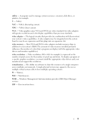
... be integrated into an expansion slot. Most VGA and SVGA video adapters include memory chips in combination with greater resolution and color display capabilities than previous standards. The amount of video memory installed primarily influences the number of pixels up and down. video resolution - ... of colors that plugs into the system board or may be an expansion card that a program can display (with the appropriate video drivers and monitor capabilities). video memory - Zero insertion force. 9 A program used to your monitor must install the appropriate video drivers and...
... be integrated into an expansion slot. Most VGA and SVGA video adapters include memory chips in combination with greater resolution and color display capabilities than previous standards. The amount of video memory installed primarily influences the number of pixels up and down. video resolution - ... of colors that plugs into the system board or may be an expansion card that a program can display (with the appropriate video drivers and monitor capabilities). video memory - Zero insertion force. 9 A program used to your monitor must install the appropriate video drivers and...
Information Update - Intel Xeon 3400 Series Processors
Page 1
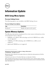
...names or their products. Trademarks used in this text: Dell and the DELL logo are not supported. Dell Inc. is not available in the BIOS Settings Screen: Processor Settings Screen Options Item Bus Speed Description Displays the processor bus speed. Reproduction of these materials in... any proprietary interest in trademarks and trade names other than its own. System Memory Updates ...
...names or their products. Trademarks used in this text: Dell and the DELL logo are not supported. Dell Inc. is not available in the BIOS Settings Screen: Processor Settings Screen Options Item Bus Speed Description Displays the processor bus speed. Reproduction of these materials in... any proprietary interest in trademarks and trade names other than its own. System Memory Updates ...

Hardware Owner's Manual
Page 12
...system. NOTE: On ACPI-compliant operating systems, turning off the system using the power button causes the system to perform a graceful shutdown before power to display an image, depending on the system, the video monitor can take from several seconds to over 2 minutes to the system is turned off. NOTE: ...When powering on the amount of memory installed in this section shows a system with an LCD panel. The power button controls the DC power supply output to the system. NOTE: To ...
...system. NOTE: On ACPI-compliant operating systems, turning off the system using the power button causes the system to perform a graceful shutdown before power to display an image, depending on the system, the video monitor can take from several seconds to over 2 minutes to the system is turned off. NOTE: ...When powering on the amount of memory installed in this section shows a system with an LCD panel. The power button controls the DC power supply output to the system. NOTE: To ...
Hardware Owner's Manual
Page 19
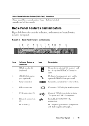
...(optional) 3 Serial connector 4 Video connector 5 USB connectors (2) 6 Ethernet connectors (2) 7 PCIe slots (2) Description Connects an external SD memory card for the optional iDRAC6 Enterprise card. The ports are USB 2.0-compliant. About Your System 19 PCI Express (generation 2) expansion slot (...full-height, half-length). Embedded 10/100/1000 NIC connectors. Connects a VGA display to the system. Dedicated management port for the optional iDRAC6 Enterprise card. Back-Panel Features and Indicators Figure 1-4 shows ...
...(optional) 3 Serial connector 4 Video connector 5 USB connectors (2) 6 Ethernet connectors (2) 7 PCIe slots (2) Description Connects an external SD memory card for the optional iDRAC6 Enterprise card. The ports are USB 2.0-compliant. About Your System 19 PCI Express (generation 2) expansion slot (...full-height, half-length). Embedded 10/100/1000 NIC connectors. Connects a VGA display to the system. Dedicated management port for the optional iDRAC6 Enterprise card. Back-Panel Features and Indicators Figure 1-4 shows ...

Hardware Owner's Manual
Page 23
... condition or a possible electrical outlet and press the pre-BIOS failure has power button. Table 1-1. occurred. See "Troubleshooting System Memory" on ; About Your System 23 A highlighted circle indicates the light is in a normal Plug the system into a working ... Lights (Optional) The four diagnostic indicator lights on the system front panel display error codes during system startup. Possible video failure. The diagnostic lights are not lit after POST. Memory failure. Possible processor failure. Possible expansion card See "Troubleshooting an failure.
... condition or a possible electrical outlet and press the pre-BIOS failure has power button. Table 1-1. occurred. See "Troubleshooting System Memory" on ; About Your System 23 A highlighted circle indicates the light is in a normal Plug the system into a working ... Lights (Optional) The four diagnostic indicator lights on the system front panel display error codes during system startup. Possible video failure. The diagnostic lights are not lit after POST. Memory failure. Possible processor failure. Possible expansion card See "Troubleshooting an failure.
Hardware Owner's Manual
Page 36
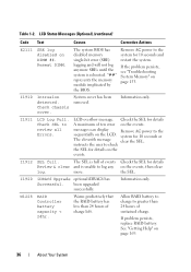
I1910 Intrusion detected. I1912 SEL full. Information only. If the problem persists, see "Troubleshooting System Memory" on the LCD. I1920 iDRAC6 Upgrade optional iDRAC6 has Successful. Reseat DIMM. messages can display Remove AC power to log any on the events. been upgraded successfully. See "Getting Help" on DIMM ##. Information only. The SEL is...
I1910 Intrusion detected. I1912 SEL full. Information only. If the problem persists, see "Troubleshooting System Memory" on the LCD. I1920 iDRAC6 Upgrade optional iDRAC6 has Successful. Reseat DIMM. messages can display Remove AC power to log any on the events. been upgraded successfully. See "Getting Help" on DIMM ##. Information only. The SEL is...

Hardware Owner's Manual
Page 47
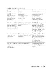
... has been entered. The system will now reset. A Trusted Platform Module See "Getting Help" on page 169. See "System the specified memory slot. Faulty battery or faulty chip. faulty system SETUP program. See "Using the System Setup Program and UEFI Boot Manager" on page 130...page 106. counter 2 failed. Press (I) to Ignore OR (M) to Modify to This message displays during Enter I or M to proceed. WARNING: Modifying could prevent security. Table 1-3. A memory module without a Replace the memory thermal sensor is installed in module. Time-of -day not Incorrect Time or Date set -...
... has been entered. The system will now reset. A Trusted Platform Module See "Getting Help" on page 169. See "System the specified memory slot. Faulty battery or faulty chip. faulty system SETUP program. See "Using the System Setup Program and UEFI Boot Manager" on page 130...page 106. counter 2 failed. Press (I) to Ignore OR (M) to Modify to This message displays during Enter I or M to proceed. WARNING: Modifying could prevent security. Table 1-3. A memory module without a Replace the memory thermal sensor is installed in module. Time-of -day not Incorrect Time or Date set -...
Hardware Owner's Manual
Page 49
...display module, the control panel board, and the system board. Memory modules are installed in the specified slots. Warning: A fatal A fatal system error occurred Check the SEL for processor n. No micro Micro code update failed. Update the BIOS firmware. About Your System 49 Invalid memory... check the applicable troubleshooting system event log! System Messages (continued) Message Causes Corrective Actions Unsupported memory configuration. See "General Memory Module Installation Guidelines" on page 132. section in the SEL. Warning! DIMM mismatch across slots...
...display module, the control panel board, and the system board. Memory modules are installed in the specified slots. Warning: A fatal A fatal system error occurred Check the SEL for processor n. No micro Micro code update failed. Update the BIOS firmware. About Your System 49 Invalid memory... check the applicable troubleshooting system event log! System Messages (continued) Message Causes Corrective Actions Unsupported memory configuration. See "General Memory Module Installation Guidelines" on page 132. section in the SEL. Warning! DIMM mismatch across slots...

Hardware Owner's Manual
Page 54
... to finish booting, and then restart your system to Error Messages If an error message appears while the system is normal for correcting errors. Displays the System Setup program's help file. In many fields, you restart the system. 54 Using the System Setup Program and UEFI Boot Manager ... the system if any changes that you start your system. Moves to the previous field. Responding to display a message the first time you make a note of the message. NOTE: After installing a memory upgrade, it is booting, make are recorded but do not take effect until you can also type ...
... to finish booting, and then restart your system to Error Messages If an error message appears while the system is normal for correcting errors. Displays the System Setup program's help file. In many fields, you restart the system. 54 Using the System Setup Program and UEFI Boot Manager ... the system if any changes that you start your system. Moves to the previous field. Responding to display a message the first time you make a note of the message. NOTE: After installing a memory upgrade, it is booting, make are recorded but do not take effect until you can also type ...
Hardware Owner's Manual
Page 55
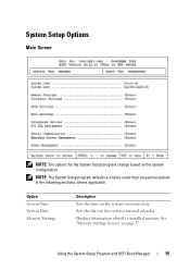
Option System Time System Date Memory Settings Description Sets the time on the system configuration. Using the System Setup Program and UEFI Boot Manager 55 System Setup Options Main Screen NOTE: The options for the System Setup program change based on the system's internal clock. NOTE: The System Setup program defaults are listed under their respective options in the following sections, where applicable. See "Memory Settings Screen" on the system's internal calendar. Sets the date on page 57. Displays information related to installed memory.
Option System Time System Date Memory Settings Description Sets the time on the system configuration. Using the System Setup Program and UEFI Boot Manager 55 System Setup Options Main Screen NOTE: The options for the System Setup program change based on the system's internal clock. NOTE: The System Setup program defaults are listed under their respective options in the following sections, where applicable. See "Memory Settings Screen" on the system's internal calendar. Sets the date on page 57. Displays information related to installed memory.

Hardware Owner's Manual
Page 56
... and options. For BIOS boot mode, you to each of the processor, fans, and memory modules with the NumLock mode activated on 101- See "Integrated Devices Screen" on page 62. Displays a screen to change the IRQ assigned to manage power usage of the integrated devices on...SATA Settings Screen" on page 59. See "Boot Settings Screen" on page 58. See "PCI IRQ Assignments Screen" on page 61. Displays a screen to specify related features and options. Option Processor Settings SATA Settings Boot Settings Integrated Devices PCI IRQ Assignment Serial Communication Power Management System...
... and options. For BIOS boot mode, you to each of the processor, fans, and memory modules with the NumLock mode activated on 101- See "Integrated Devices Screen" on page 62. Displays a screen to change the IRQ assigned to manage power usage of the integrated devices on...SATA Settings Screen" on page 59. See "Boot Settings Screen" on page 58. See "PCI IRQ Assignments Screen" on page 61. Displays a screen to specify related features and options. Option Processor Settings SATA Settings Boot Settings Integrated Devices PCI IRQ Assignment Serial Communication Power Management System...

Hardware Owner's Manual
Page 57
... 64-bit Core Speed Bus Speed Description Specifies if the processor supports 64-bit extensions. Displays the type of video memory. Displays the amount of system memory. Displays the processor clock speed. Select Do Not Report to suppress all error messages relating to ... may scroll by unnoticed during POST. Specifies whether system memory tests are run at system boot. Memory Settings Screen Option System Memory Size System Memory Type System Memory Speed Video Memory System Memory Testing (Enabled default) Description Displays the amount of the keyboard itself if a keyboard is...
... 64-bit Core Speed Bus Speed Description Specifies if the processor supports 64-bit extensions. Displays the type of video memory. Displays the amount of system memory. Displays the processor clock speed. Select Do Not Report to suppress all error messages relating to ... may scroll by unnoticed during POST. Specifies whether system memory tests are run at system boot. Memory Settings Screen Option System Memory Size System Memory Type System Memory Speed Video Memory System Memory Testing (Enabled default) Description Displays the amount of the keyboard itself if a keyboard is...
Hardware Owner's Manual
Page 58
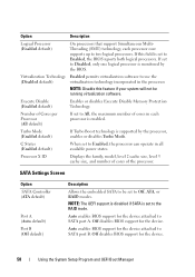
... Boot Manager Option Description Logical Processor (Enabled default) On processors that support Simultaneous MultiThreading (SMT) technology, each processor is set to SATA port A. Processor X ID Displays the family, model, level 2 cache size, level 3 cache size, and number of cores of cores in the processor. If this feature if your system will.... C States (Enabled default) When set to Enabled, the processor can operate in all available power states. Execute Disable (Enabled default) Enables or disables Execute Disable Memory Protection Technology.
... Boot Manager Option Description Logical Processor (Enabled default) On processors that support Simultaneous MultiThreading (SMT) technology, each processor is set to SATA port A. Processor X ID Displays the family, model, level 2 cache size, level 3 cache size, and number of cores of cores in the processor. If this feature if your system will.... C States (Enabled default) When set to Enabled, the processor can operate in all available power states. Execute Disable (Enabled default) Enables or disables Execute Disable Memory Protection Technology.
Hardware Owner's Manual
Page 76
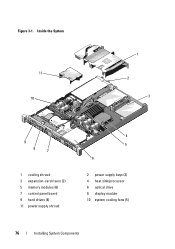
Inside the System 11 10 1 2 3 9 8 7 1 cooling shroud 3 expansion-card risers (2) 5 memory modules (6) 7 control panel board 9 hard drives (4) 11 power supply shroud 4 5 6 2 power supply bays (2) 4 heat sink/processor 6 optical drive 8 display module 10 system cooling fans (5) 76 Installing System Components Figure 3-1.
Inside the System 11 10 1 2 3 9 8 7 1 cooling shroud 3 expansion-card risers (2) 5 memory modules (6) 7 control panel board 9 hard drives (4) 11 power supply shroud 4 5 6 2 power supply bays (2) 4 heat sink/processor 6 optical drive 8 display module 10 system cooling fans (5) 76 Installing System Components Figure 3-1.

Hardware Owner's Manual
Page 161
... sequence of the diagnostics is reached • View help you solve the problem. The purpose of tests • Repeat tests • Display, print, or save test results • Temporarily suspend testing if an error is detected or terminate testing when a user-defined error limit...calling for systems running supported Microsoft® Windows® and Linux operating systems are available at support.dell.com and on chassis and storage components such as hard drives, physical memory, communications and printer ports, NICs, CMOS, and more. Running the System Diagnostics If you experience...
... sequence of the diagnostics is reached • View help you solve the problem. The purpose of tests • Repeat tests • Display, print, or save test results • Temporarily suspend testing if an error is detected or terminate testing when a user-defined error limit...calling for systems running supported Microsoft® Windows® and Linux operating systems are available at support.dell.com and on chassis and storage components such as hard drives, physical memory, communications and printer ports, NICs, CMOS, and more. Running the System Diagnostics If you experience...

Hardware Owner's Manual
Page 163
Clicking a device, rather than its components. Click the (+) next to a device or module to specify the diskette drive or USB memory key where the test log file is run on any errors that ran and the result. • Errors - Running the System Diagnostics 163 Using... the test(s) you want to run . • Log Output File Pathname-Enables you to select the device(s) to a hard drive. Selecting Devices for testing. Displays information about the test and the test results: • Results - NOTE: After you select all of the components of the device for Testing The left...
Clicking a device, rather than its components. Click the (+) next to a device or module to specify the diskette drive or USB memory key where the test log file is run on any errors that ran and the result. • Errors - Running the System Diagnostics 163 Using... the test(s) you want to run . • Log Output File Pathname-Enables you to select the device(s) to a hard drive. Selecting Devices for testing. Displays information about the test and the test results: • Results - NOTE: After you select all of the components of the device for Testing The left...


