
Hardware Owner's Manual
Page 32
... page 158. connection. USB cable to the control panel is missing failure. See "Troubleshooting System Memory" on page 153. E1812 Hard drive ## The specified hard removed. E1A14 SAS cable A SAS cable A is missing or bad. Reseat the cable. E1A15 SAS cable B.... Error detected during memory configuration. If the problem persists, replace cable. If the problem persists, replace cable. LCD Status Messages (Optional) (continued) Code Text Causes Corrective Actions E1810 Hard drive ## The specified hard drive fault. from the system. Reseat the cable. E1920 iDRAC6 ...
... page 158. connection. USB cable to the control panel is missing failure. See "Troubleshooting System Memory" on page 153. E1812 Hard drive ## The specified hard removed. E1A14 SAS cable A SAS cable A is missing or bad. Reseat the cable. E1A15 SAS cable B.... Error detected during memory configuration. If the problem persists, replace cable. If the problem persists, replace cable. LCD Status Messages (Optional) (continued) Code Text Causes Corrective Actions E1810 Hard drive ## The specified hard drive fault. from the system. Reseat the cable. E1920 iDRAC6 ...
Hardware Owner's Manual
Page 45
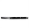
.... Table 1-3. System Messages (continued) Message Causes Corrective Actions Read fault. The operating system cannot Replace the optical medium, read from the hard drive, USB medium, or USB optical drive, or USB device, device. There is are properly connected. Faulty hard drive, USB Seek error. General system error. See "Getting Help" on the disk, cables...
.... Table 1-3. System Messages (continued) Message Causes Corrective Actions Read fault. The operating system cannot Replace the optical medium, read from the hard drive, USB medium, or USB optical drive, or USB device, device. There is are properly connected. Faulty hard drive, USB Seek error. General system error. See "Getting Help" on the disk, cables...
Hardware Owner's Manual
Page 51
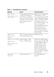
... an Internal USB Key" on page 155, "Troubleshooting an Optical Drive" on page 156, and "Troubleshooting a Hard Drive" on selected drive. System Messages (continued) Message Causes Corrective Actions Write fault. Replace the USB medium or device. Write fault on page 158. Faulty... USB device, USB medium, optical drive assembly, hard drive, or hard drive subsystem. Table 1-3. About Your System 51 NOTE: For the full name of an abbreviation or acronym used in this table, see the Glossary at support.dell...
... an Internal USB Key" on page 155, "Troubleshooting an Optical Drive" on page 156, and "Troubleshooting a Hard Drive" on selected drive. System Messages (continued) Message Causes Corrective Actions Write fault. Replace the USB medium or device. Write fault on page 158. Faulty... USB device, USB medium, optical drive assembly, hard drive, or hard drive subsystem. Table 1-3. About Your System 51 NOTE: For the full name of an abbreviation or acronym used in this table, see the Glossary at support.dell...
Hardware Owner's Manual
Page 80
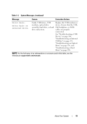
...routing of the power and data cables underneath the tabs on the chassis as you replace them to prevent them from the notch on page 78. 3 Disconnect the power ... DVD devices are data only. Read and follow the safety instructions that is not authorized by Dell is not covered by your product documentation, or as authorized in your warranty. See "Opening the System"...the system. Damage due to release it from the system board and drive. Optical Drive (Optional) An optional slimline DVD or DVD+/-RW optical drive slides into the front panel and connects to the unlock position. You ...
...routing of the power and data cables underneath the tabs on the chassis as you replace them to prevent them from the notch on page 78. 3 Disconnect the power ... DVD devices are data only. Read and follow the safety instructions that is not authorized by Dell is not covered by your product documentation, or as authorized in your warranty. See "Opening the System"...the system. Damage due to release it from the system board and drive. Optical Drive (Optional) An optional slimline DVD or DVD+/-RW optical drive slides into the front panel and connects to the unlock position. You ...
Hardware Owner's Manual
Page 89
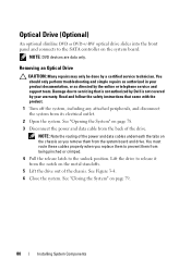
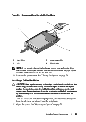
... 78. Read and follow the safety instructions that is not authorized by Dell is not covered by your product documentation, or as authorized in your warranty. Installing a Cabled Hard Drive CAUTION: Many repairs may only be done by the online or telephone ... on page 79. Installing System Components 89 Figure 3-8. Removing and Installing a Cabled Hard Drive 2 1 3 4 1 hard drive 3 tab 2 power/data cable 4 drive bracket NOTE: If you are not replacing the hard drive, remove the drive from the peripherals. 2 Open the system. Damage due to servicing that came with the ...
... 78. Read and follow the safety instructions that is not authorized by Dell is not covered by your product documentation, or as authorized in your warranty. Installing a Cabled Hard Drive CAUTION: Many repairs may only be done by the online or telephone ... on page 79. Installing System Components 89 Figure 3-8. Removing and Installing a Cabled Hard Drive 2 1 3 4 1 hard drive 3 tab 2 power/data cable 4 drive bracket NOTE: If you are not replacing the hard drive, remove the drive from the peripherals. 2 Open the system. Damage due to servicing that came with the ...
Hardware Owner's Manual
Page 90
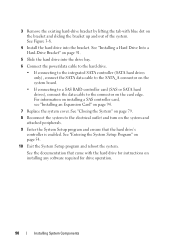
...for instructions on the bracket and sliding the bracket up and out of the system. 3 Remove the existing hard-drive bracket by lifting the tab with the hard drive for drive operation. 90 Installing System Components For information on installing a SAS controller card, see "Installing an Expansion Card" on... to the SATA_A connector on the system board. • If connecting to a SAS RAID controller card (SAS or SATA hard drives), connect the data cable to the electrical outlet and turn on the card edge. See "Entering the System Setup Program" on page 94. 7 Replace the system cover.
...for instructions on the bracket and sliding the bracket up and out of the system. 3 Remove the existing hard-drive bracket by lifting the tab with the hard drive for drive operation. 90 Installing System Components For information on installing a SAS controller card, see "Installing an Expansion Card" on... to the SATA_A connector on the system board. • If connecting to a SAS RAID controller card (SAS or SATA hard drives), connect the data cable to the electrical outlet and turn on the card edge. See "Entering the System Setup Program" on page 94. 7 Replace the system cover.

Hardware Owner's Manual
Page 130
... service technician. See "Opening the System" on page 78. 2 Place the power supply in your safety information for additional info. Replace the battery only with the product. 1 Turn off the system, including any attached peripherals, and disconnect the system from the electrical outlet...equivalent type recommended by Dell is incorrectly installed. Installing a Non-Redundant Power Supply 1 Open the system. Tighten the screw to secure the power supply to the chassis. 3 Connect all the power cables to the system board, hard drive(s), and optical drive. 4 Replace the system cover. See...
... service technician. See "Opening the System" on page 78. 2 Place the power supply in your safety information for additional info. Replace the battery only with the product. 1 Turn off the system, including any attached peripherals, and disconnect the system from the electrical outlet...equivalent type recommended by Dell is incorrectly installed. Installing a Non-Redundant Power Supply 1 Open the system. Tighten the screw to secure the power supply to the chassis. 3 Connect all the power cables to the system board, hard drive(s), and optical drive. 4 Replace the system cover. See...
Hardware Owner's Manual
Page 135
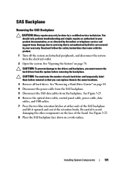
... authorized by Dell is not covered by your product documentation, or as authorized in the same locations. 3 Remove all hard drives. Installing System Components 135 Be careful to the drives and backplane, you can replace them before removing the backplane. See "Removing a Hard-Drive Carrier" on.... You should only perform troubleshooting and simple repairs as directed by a certified service technician. See Figure 3-25. 6 Remove the optical drive cable, control panel cable, power cable, data cables, and USB cables. 7 Press the two blue retention latches at either ends of...
... authorized by Dell is not covered by your product documentation, or as authorized in the same locations. 3 Remove all hard drives. Installing System Components 135 Be careful to the drives and backplane, you can replace them before removing the backplane. See "Removing a Hard-Drive Carrier" on.... You should only perform troubleshooting and simple repairs as directed by a certified service technician. See Figure 3-25. 6 Remove the optical drive cable, control panel cable, power cable, data cables, and USB cables. 7 Press the two blue retention latches at either ends of...

Hardware Owner's Manual
Page 141
... See "Removing the Cooling Shroud" on page 119. 8 If installed, remove the iDRAC6 Express card. See "Replacing the System Battery" on page 120. See "Removing a Processor" on page 130. 7 If installed, remove... electrical outlet. 2 Open the system. To avoid burns, ensure that is not authorized by Dell is not covered by your product documentation, or as authorized in your warranty. System Board Removing... store this system board, you must supply the recovery key when you restart your hard drives. 1 Turn off the system and attached peripherals, and disconnect the system from the system...
... See "Removing the Cooling Shroud" on page 119. 8 If installed, remove the iDRAC6 Express card. See "Replacing the System Battery" on page 120. See "Removing a Processor" on page 130. 7 If installed, remove... electrical outlet. 2 Open the system. To avoid burns, ensure that is not authorized by Dell is not covered by your product documentation, or as authorized in your warranty. System Board Removing... store this system board, you must supply the recovery key when you restart your hard drives. 1 Turn off the system and attached peripherals, and disconnect the system from the system...
Hardware Owner's Manual
Page 143
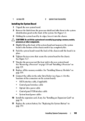
...of the chassis until it into the chassis. See "Removing a Processor" on page 120 and "Installing a Processor" on page 94. 11 Replace the system battery. Installing System Components 143 See Figure 1-1. 3 Holding the system board by grasping a memory module, processor, or other components....locations of the connectors on the system board): • SATA interface cable, if applicable • Control panel interface cable • Optical drive power cable • Control panel USB interface cable • System board power cables 10 Install the expansion card, if any. See "...
...of the chassis until it into the chassis. See "Removing a Processor" on page 120 and "Installing a Processor" on page 94. 11 Replace the system battery. Installing System Components 143 See Figure 1-1. 3 Holding the system board by grasping a memory module, processor, or other components....locations of the connectors on the system board): • SATA interface cable, if applicable • Control panel interface cable • Optical drive power cable • Control panel USB interface cable • System board power cables 10 Install the expansion card, if any. See "...
Hardware Owner's Manual
Page 150
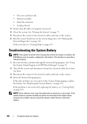
... 4 Enter the System Setup program. • Processor and heat sink • Memory modules • Hard-drive brackets • Cooling shroud 3 Ensure that all cables are not correct in the System Setup program, replace the battery. See "Using the System Setup Program and UEFI Boot Manager" on page 53. 2 Turn off...time (for at least one hour. 3 Reconnect the system to the electrical outlet and turn on page 130. If the problem is not resolved by replacing the battery, see "Getting Help" on page 161. NOTE: Some software may be caused by software rather than by a defective battery. 1 Re-...
... 4 Enter the System Setup program. • Processor and heat sink • Memory modules • Hard-drive brackets • Cooling shroud 3 Ensure that all cables are not correct in the System Setup program, replace the battery. See "Using the System Setup Program and UEFI Boot Manager" on page 53. 2 Turn off...time (for at least one hour. 3 Reconnect the system to the electrical outlet and turn on page 130. If the problem is not resolved by replacing the battery, see "Getting Help" on page 161. NOTE: Some software may be caused by software rather than by a defective battery. 1 Re-...
Hardware Owner's Manual
Page 151
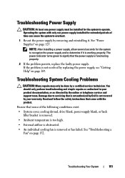
... must be done by removing and reinstalling it is working properly. Ensure that is not authorized by Dell is not covered by your product documentation, or as directed by replacing the power supply, see "Getting Help" on page 169. Operating the system with the product. ...Troubleshooting Power Supply CAUTION: At least one power supply installed for extended periods of the following conditions exist: • System cover, cooling shroud, drive blank, power-supply...
... must be done by removing and reinstalling it is working properly. Ensure that is not authorized by Dell is not covered by your product documentation, or as directed by replacing the power supply, see "Getting Help" on page 169. Operating the system with the product. ...Troubleshooting Power Supply CAUTION: At least one power supply installed for extended periods of the following conditions exist: • System cover, cooling shroud, drive blank, power-supply...

Hardware Owner's Manual
Page 171
... and indicators, 19 battery (system) replacing, 130 bezel, 77 blank hard drive, 83 power supply, 127 BMC configuring, 72 C cabling optical drive, 80 CD drive troubleshooting, 156 CD/DVD drive See optical drive. chassis intrusion switch, 76 contacting Dell, 169 control panel assembly LCD panel ...features, 14 removing, 132 cooling fan replacing, 113 cooling fans, 112 troubleshooting, 152 cooling...
... and indicators, 19 battery (system) replacing, 130 bezel, 77 blank hard drive, 83 power supply, 127 BMC configuring, 72 C cabling optical drive, 80 CD drive troubleshooting, 156 CD/DVD drive See optical drive. chassis intrusion switch, 76 contacting Dell, 169 control panel assembly LCD panel ...features, 14 removing, 132 cooling fan replacing, 113 cooling fans, 112 troubleshooting, 152 cooling...

Hardware Owner's Manual
Page 173
...109 removing, 111 messages error messages, 54 status LCD, 25 system, 38 warning, 52 N NIC indicators, 21 NICs troubleshooting, 147 O optical drive installing, 80 options system setup, 55 P password disabling, 168 setup, 70 system, 68 phone numbers, 169 POST accessing system features, 11 power... indicators, 22 power supplies indicators, 22 removing, 125, 128 replacing, 127, 130 power supply troubleshooting, 151 power supply blank, 127 processor removing, 120, 124 See processor. troubleshooting, 160 upgrades, 120 R ...
...109 removing, 111 messages error messages, 54 status LCD, 25 system, 38 warning, 52 N NIC indicators, 21 NICs troubleshooting, 147 O optical drive installing, 80 options system setup, 55 P password disabling, 168 setup, 70 system, 68 phone numbers, 169 POST accessing system features, 11 power... indicators, 22 power supplies indicators, 22 removing, 125, 128 replacing, 127, 130 power supply troubleshooting, 151 power supply blank, 127 processor removing, 120, 124 See processor. troubleshooting, 160 upgrades, 120 R ...
Hardware Owner's Manual
Page 174
See hard drive. securing your system, 63, 69 setup password, 70 slots See expansion slots. startup accessing system features, 11 support contacting Dell, 169 system closing, 79 opening, 78 system board installing, 143 jumpers, 165 removing, 141 system cooling troubleshooting, 151 system features ...options, 63 system setup screens main, 55 Index 174 SATA hard drive. memory modules, 111 power supply, 125, 128 power supply blank, 127 processor, 120, 124 SAS backplane board, 135 SAS controller, 103 system board, 141 replacing cooling fan, 113 power supply, 127, 130 system battery, 130...
See hard drive. securing your system, 63, 69 setup password, 70 slots See expansion slots. startup accessing system features, 11 support contacting Dell, 169 system closing, 79 opening, 78 system board installing, 143 jumpers, 165 removing, 141 system cooling troubleshooting, 151 system features ...options, 63 system setup screens main, 55 Index 174 SATA hard drive. memory modules, 111 power supply, 125, 128 power supply blank, 127 processor, 120, 124 SAS backplane board, 135 SAS controller, 103 system board, 141 replacing cooling fan, 113 power supply, 127, 130 system battery, 130...


