
Glossary
Page 1
... bus - Common Information Model describes the management information utilized by an administrator, for quick data retrieval. Advanced Configuration and Power Interface. American National Standards Institute. blade - BMC - BTU - An information pathway between the processor and RAM. asset...purposes. Centimeter(s). 1 ACPI - ANSI - backup - The modules are mounted into a chassis that includes power supplies and fans. CIM - Dell™ Glossary NOTE: For additional information on storage terminology, visit the Storage Networking Industry Association's website at...
... bus - Common Information Model describes the management information utilized by an administrator, for quick data retrieval. Advanced Configuration and Power Interface. American National Standards Institute. blade - BMC - BTU - An information pathway between the processor and RAM. asset...purposes. Centimeter(s). 1 ACPI - ANSI - backup - The modules are mounted into a chassis that includes power supplies and fans. CIM - Dell™ Glossary NOTE: For additional information on storage terminology, visit the Storage Networking Industry Association's website at...

Glossary
Page 8
...(unbuffered) DDR3 memory module. See RAM. Transmission Control Protocol/Internet Protocol. Some devices (such as password protection. TOE - U-DIMM - Uninterruptible power supply. A USB connector provides a single connection point for multiple USB-compliant devices, such as the processor(s), RAM, controllers for the devices. A ... switch used by an operating system, where each disk. Used to describe a system that automatically supplies power to I/O devices. A port on each processor has equal access to your system's integral components, such as mice and keyboards....
...(unbuffered) DDR3 memory module. See RAM. Transmission Control Protocol/Internet Protocol. Some devices (such as password protection. TOE - U-DIMM - Uninterruptible power supply. A USB connector provides a single connection point for multiple USB-compliant devices, such as the processor(s), RAM, controllers for the devices. A ... switch used by an operating system, where each disk. Used to describe a system that automatically supplies power to I/O devices. A port on each processor has equal access to your system's integral components, such as mice and keyboards....

Glossary
Page 48
... Protocol/Internet Protocol TOE - Unregistered DDR3 UPS - Watt WH - TCP/IP U-DIMM - Watt-hour WMI - Super video graphics array VGA と SVGA TCP/IP - Uninterruptible power supply USB - Universal Serial Bus USB USB USB USB V - Volt direct current VGA - Video graphics array VGA と SVGA W - Self-Monitoring Analysis and Reporting Technology BIOS...
... Protocol/Internet Protocol TOE - Unregistered DDR3 UPS - Watt WH - TCP/IP U-DIMM - Watt-hour WMI - Super video graphics array VGA と SVGA TCP/IP - Uninterruptible power supply USB - Universal Serial Bus USB USB USB USB V - Volt direct current VGA - Video graphics array VGA と SVGA W - Self-Monitoring Analysis and Reporting Technology BIOS...

Glossary
Page 58
Windows Management Instrumentation 은 CIM ZIF Zero Insertion Force provider CIM management station managed system) 은 Dell OpenManage™ Server Administrator x x y x z 58 TCP/IP TCP/IP Offload Engine U-DIMM DDR3 Unregistered(Unbuffered) DDR3 Memory Module UPS Uninterruptible Power Supply USB Universal Serial Bus USB USB USB USB V - 볼트 (Volt VAC Volt Alternating Current...
Windows Management Instrumentation 은 CIM ZIF Zero Insertion Force provider CIM management station managed system) 은 Dell OpenManage™ Server Administrator x x y x z 58 TCP/IP TCP/IP Offload Engine U-DIMM DDR3 Unregistered(Unbuffered) DDR3 Memory Module UPS Uninterruptible Power Supply USB Universal Serial Bus USB USB USB USB V - 볼트 (Volt VAC Volt Alternating Current...

Information Update - Power Infrastructure Sizing
Page 1
... can be less efficient and more accurately approximate the appropriate size of the power supply power rating. June 2009 Systems characterized while using the power capping features enabled from Dell may result in 500W of power consumption for peak power consumption. Combined use of system and workload characterization with circuit protection devices such as 20KW. Example: If...
... can be less efficient and more accurately approximate the appropriate size of the power supply power rating. June 2009 Systems characterized while using the power capping features enabled from Dell may result in 500W of power consumption for peak power consumption. Combined use of system and workload characterization with circuit protection devices such as 20KW. Example: If...
Getting Started Guide
Page 7
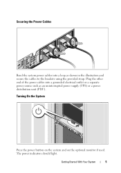
Securing the Power Cables Bend the system power cables into a grounded electrical outlet or a separate power source such as shown in the illustration and secure the cables to the brackets using the provided strap. Turning On the System Press the power button on the system and on the optional monitor if used. Getting Started With Your System 5 The power indicators should light. Plug the other end of the power cables into a loop as an uninterrupted power supply (UPS) or a power distribution unit (PDU).
Securing the Power Cables Bend the system power cables into a grounded electrical outlet or a separate power source such as shown in the illustration and secure the cables to the brackets using the provided strap. Turning On the System Press the power button on the system and on the optional monitor if used. Getting Started With Your System 5 The power indicators should light. Plug the other end of the power cables into a loop as an uninterrupted power supply (UPS) or a power distribution unit (PDU).
Getting Started Guide
Page 12
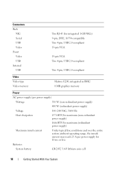
... type Video memory Matrox G200, integrated in BMC 8 MB graphics memory Power AC power supply (per power supply) Wattage 350 W (non-redundant power supply) 400 W (redundant power supply) Voltage 100-240 VAC, 50/60 Hz Heat dissipation 1571 BTU/hr maximum (non-redundant power supply) 1666 BTU/hr maximum (redundant power supply) Maximum inrush current Under typical line conditions and over the entire...
... type Video memory Matrox G200, integrated in BMC 8 MB graphics memory Power AC power supply (per power supply) Wattage 350 W (non-redundant power supply) 400 W (redundant power supply) Voltage 100-240 VAC, 50/60 Hz Heat dissipation 1571 BTU/hr maximum (non-redundant power supply) 1666 BTU/hr maximum (redundant power supply) Maximum inrush current Under typical line conditions and over the entire...

Hardware Owner's Manual
Page 7
... 120 Removing a VFlash Media Card 120 Processor 120 Removing a Processor 120 Installing a Processor 124 Power Supplies 125 Removing a Redundant Power Supply 125 Installing a Redundant Power Supply 127 Removing the Power Supply Blank 127 Installing the Power Supply Blank 127 Removing a Non-Redundant Power Supply 128 Installing a Non-Redundant Power Supply 130 System Battery 130 Replacing the System Battery 130 Control Panel Assembly 132 Removing...
... 120 Removing a VFlash Media Card 120 Processor 120 Removing a Processor 120 Installing a Processor 124 Power Supplies 125 Removing a Redundant Power Supply 125 Installing a Redundant Power Supply 127 Removing the Power Supply Blank 127 Installing the Power Supply Blank 127 Removing a Non-Redundant Power Supply 128 Installing a Non-Redundant Power Supply 130 System Battery 130 Replacing the System Battery 130 Control Panel Assembly 132 Removing...

Hardware Owner's Manual
Page 8
SAS Backplane 135 Removing the SAS Backplane 135 Installing the SAS Backplane 137 Power Distribution Board 138 Removing the Power Distribution Board 138 Replacing the Power Distribution Board 140 System Board 141 Removing the System Board 141 Installing the System Board 143 4 Troubleshooting Your System 145 ...146 Troubleshooting a Serial I/O Device 147 Troubleshooting a NIC 147 Troubleshooting a Wet System 148 Troubleshooting a Damaged System 149 Troubleshooting the System Battery 150 Troubleshooting Power Supply 151 Troubleshooting System Cooling Problems 151 8 Contents
SAS Backplane 135 Removing the SAS Backplane 135 Installing the SAS Backplane 137 Power Distribution Board 138 Removing the Power Distribution Board 138 Replacing the Power Distribution Board 140 System Board 141 Removing the System Board 141 Installing the System Board 143 4 Troubleshooting Your System 145 ...146 Troubleshooting a Serial I/O Device 147 Troubleshooting a NIC 147 Troubleshooting a Wet System 148 Troubleshooting a Damaged System 149 Troubleshooting the System Battery 150 Troubleshooting Power Supply 151 Troubleshooting System Cooling Problems 151 8 Contents

Hardware Owner's Manual
Page 12
...Power-on indicator, power button Description The power-on indicator lights when the system power is turned off the system using the power button causes the system to perform a graceful shutdown before power to the system is on. When the optional system bezel is installed, the power button is not accessible. The power button controls the DC power supply... output to display an image, depending on the configuration, your system may have an LCD panel or LED diagnostic indicators. NOTE: When powering on the...
...Power-on indicator, power button Description The power-on indicator lights when the system power is turned off the system using the power button causes the system to perform a graceful shutdown before power to the system is on. When the optional system bezel is installed, the power button is not accessible. The power button controls the DC power supply... output to display an image, depending on the configuration, your system may have an LCD panel or LED diagnostic indicators. NOTE: When powering on the...

Hardware Owner's Manual
Page 20
... the identification buttons located on and off. Item Indicator, Button, or Icon Connector 8 Active ID CMA connector 9 System status indicator 10 System identification button 11 Power supply 1 (PS1) 12 Power supply 2 (PS2) Description Connector for attaching a system indicator extension cable that is pushed again. 400 W (redundant...
... the identification buttons located on and off. Item Indicator, Button, or Icon Connector 8 Active ID CMA connector 9 System status indicator 10 System identification button 11 Power supply 1 (PS1) 12 Power supply 2 (PS2) Description Connector for attaching a system indicator extension cable that is pushed again. 400 W (redundant...
Hardware Owner's Manual
Page 22
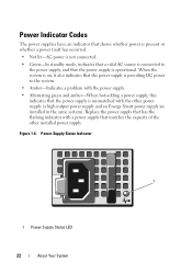
... the system. • Amber-Indicates a problem with the power supply. • Alternating green and amber-When hot-adding a power supply, this indicates that the power supply is mismatched with a power supply that the power supply is providing DC power to the power supply, and that matches the capacity of the other power supply (a high output power supply and an Energy Smart power supply are installed in the same system).
... the system. • Amber-Indicates a problem with the power supply. • Alternating green and amber-When hot-adding a power supply, this indicates that the power supply is mismatched with a power supply that the power supply is providing DC power to the power supply, and that matches the capacity of the other power supply (a high output power supply and an Energy Smart power supply are installed in the same system).
Hardware Owner's Manual
Page 29
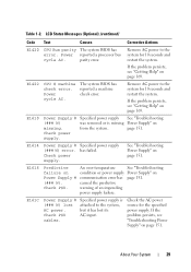
... has error. Power cycle AC. E1610 Power Supply # (### W) missing. See "Troubleshooting Power Supply" on page 151. E161C Power Supply # Specified power supply is missing from the system. Specified power supply was removed or is (### W) lost its AC input. has failed. Check PSU. Check power supply. If the problem persists, see "Getting Help" on Power Supply # (### W). Remove AC power to the system for the specified power supply. Power reported a processor...
... has error. Power cycle AC. E1610 Power Supply # (### W) missing. See "Troubleshooting Power Supply" on page 151. E161C Power Supply # Specified power supply is missing from the system. Specified power supply was removed or is (### W) lost its AC input. has failed. Check PSU. Check power supply. If the problem persists, see "Getting Help" on Power Supply # (### W). Remove AC power to the system for the specified power supply. Power reported a processor...
Hardware Owner's Manual
Page 30
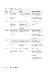
... outlined in Mismatch. Check PSU and config. Review & clear SEL. Remove AC power to the system, reduce the hardware configuration or install higher-wattage power supplies, and then restart the system. The power supply subsystem is outside of the source for more power than the power supplies can provide, even with matching wattage are not the = ### W, PSU2 same...
... outlined in Mismatch. Check PSU and config. Review & clear SEL. Remove AC power to the system, reduce the hardware configuration or install higher-wattage power supplies, and then restart the system. The power supply subsystem is outside of the source for more power than the power supplies can provide, even with matching wattage are not the = ### W, PSU2 same...
Hardware Owner's Manual
Page 37
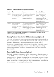
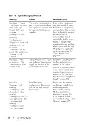
... table, see the Glossary at support.dell.com/manuals. LCD Status Messages (Optional) (continued) Code Text Causes Corrective Actions W1627 Power required > PSU wattage. Solving Problems Described by LCD Status Messages (Optional) The code and text on , the LCD message is automatically removed when that a microprocessor is a failing power supply. Check PSU and config.
... table, see the Glossary at support.dell.com/manuals. LCD Status Messages (Optional) (continued) Code Text Causes Corrective Actions W1627 Power required > PSU wattage. Solving Problems Described by LCD Status Messages (Optional) The code and text on , the LCD message is automatically removed when that a microprocessor is a failing power supply. Check PSU and config.
Hardware Owner's Manual
Page 39
...expansion cards may exceed PSU wattage. If the system boots without warning. If Energy Smart power supplies are not supported with High Output power supplies to the previous configuration. See "Power Supplies" on page 125. System fatal error during previous boot. An error caused the system to...messages for additional information for 10 seconds and restart the system. that system may power down without this warning, then the replaced component(s) are installed, replace them with this power supply. The optional iDRAC6 was remotely reset while system was booting. Alert! Table ...
...expansion cards may exceed PSU wattage. If the system boots without warning. If Energy Smart power supplies are not supported with High Output power supplies to the previous configuration. See "Power Supplies" on page 125. System fatal error during previous boot. An error caused the system to...messages for additional information for 10 seconds and restart the system. that system may power down without this warning, then the replaced component(s) are installed, replace them with this power supply. The optional iDRAC6 was remotely reset while system was booting. Alert! Table ...
Hardware Owner's Manual
Page 50
...configuration detected. Table 1-3. component(s) are installed, replace them with this warning, configuration. If Energy Smart power supplies are not supported with the High Output power supplies to use the components. See "General Memory Module Installation Guidelines" on page 153. 50 About Your ...memory modules, were just upgraded, return PSU wattage. PSU mismatch. A High Output power supply Install two High Output or and an Energy Smart power two Energy Smart power supply are installed in the system. The recommended memory configuration is not optimal. Invalid ...
...configuration detected. Table 1-3. component(s) are installed, replace them with this warning, configuration. If Energy Smart power supplies are not supported with the High Output power supplies to use the components. See "General Memory Module Installation Guidelines" on page 153. 50 About Your ...memory modules, were just upgraded, return PSU wattage. PSU mismatch. A High Output power supply Install two High Output or and an Energy Smart power two Energy Smart power supply are installed in the system. The recommended memory configuration is not optimal. Invalid ...
Hardware Owner's Manual
Page 75
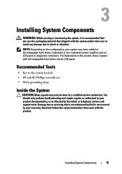
...; #1 and #2 Phillips screwdrivers • Wrist grounding strap Inside the System CAUTION: Many repairs may have cabled or hot-swappable hard drives, redundant or non-redundant power supplies, and an LCD panel or diagnostic indicators. NOTE: Depending on the configuration, your warranty. Read and follow the safety instructions that is not authorized by...
...; #1 and #2 Phillips screwdrivers • Wrist grounding strap Inside the System CAUTION: Many repairs may have cabled or hot-swappable hard drives, redundant or non-redundant power supplies, and an LCD panel or diagnostic indicators. NOTE: Depending on the configuration, your warranty. Read and follow the safety instructions that is not authorized by...
Hardware Owner's Manual
Page 76
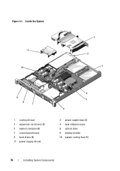
Figure 3-1. Inside the System 11 10 1 2 3 9 8 7 1 cooling shroud 3 expansion-card risers (2) 5 memory modules (6) 7 control panel board 9 hard drives (4) 11 power supply shroud 4 5 6 2 power supply bays (2) 4 heat sink/processor 6 optical drive 8 display module 10 system cooling fans (5) 76 Installing System Components
Figure 3-1. Inside the System 11 10 1 2 3 9 8 7 1 cooling shroud 3 expansion-card risers (2) 5 memory modules (6) 7 control panel board 9 hard drives (4) 11 power supply shroud 4 5 6 2 power supply bays (2) 4 heat sink/processor 6 optical drive 8 display module 10 system cooling fans (5) 76 Installing System Components

Hardware Owner's Manual
Page 101
Damage due to servicing that is not authorized by Dell is facilitated by your product documentation, or as directed by a certified service technician. The power distribution board shroud covers the power distribution board behind the power supply bay. Read and follow the safety instructions that the memory modules and heat sink have had sufficient time to...
Damage due to servicing that is not authorized by Dell is facilitated by your product documentation, or as directed by a certified service technician. The power distribution board shroud covers the power distribution board behind the power supply bay. Read and follow the safety instructions that the memory modules and heat sink have had sufficient time to...


