FTOS Command Line Reference Guide for the S55 System FTOS 8.3.5.3
Page 136
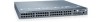
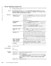
...stack-unit (S55) Force10#show hardware stack-unit stack-unit priority Display the FTOS version. Module 0 -- Module 1 -- Fan Status -- Display information about the stack ports on running processes. Configure the ability of an S-Series switch to become the management unit of a particular stack... Speed in the S-Series stack. Status : not present -- Display memory usage based on all switches in RPM Force10# Related Commands show version show processes memory (S-Series) show system stack-ports show system stack-unit 0 -- www.dell.com | support.dell.com Example Figure 4-57...
...stack-unit (S55) Force10#show hardware stack-unit stack-unit priority Display the FTOS version. Module 0 -- Module 1 -- Fan Status -- Display information about the stack ports on running processes. Configure the ability of an S-Series switch to become the management unit of a particular stack... Speed in the S-Series stack. Status : not present -- Display memory usage based on all switches in RPM Force10# Related Commands show version show processes memory (S-Series) show system stack-ports show system stack-unit 0 -- www.dell.com | support.dell.com Example Figure 4-57...
FTOS Command Line Reference Guide for the S55 System FTOS 8.3.5.3
Page 1015
... has a stacking module inserted. The commands are used for managing the stacking of S-Series systems: • power-cycle • redundancy disable-auto-reboot • redundancy force-failover stack-unit • reset stack-unit • show redundancy • show system stack-ports • stack-unit priority • stack-unit provision • stack-unit renumber • upgrade system stack-unit (S-Series stack member...
... has a stacking module inserted. The commands are used for managing the stacking of S-Series systems: • power-cycle • redundancy disable-auto-reboot • redundancy force-failover stack-unit • reset stack-unit • show redundancy • show system stack-ports • stack-unit priority • stack-unit provision • stack-unit renumber • upgrade system stack-unit (S-Series stack member...
FTOS Command Line Reference Guide for the S55 System FTOS 8.3.5.3
Page 1085
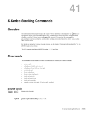
...the output of the rear modules. Defaults No default behavior or values Command Modes EXEC Privilege S-Series Debugging and Diagnostics | 1085 Enter the keywords cpu data-plane statistics to clear the counters on the selected port-pipe. You can identify stack port numbers by physical inspection... S25 models (S25N, S25P, S25V, etc.) have only port-pipe 0. Enter the keyword stack-port followed by the port number of the stacking port to clear the statistics of data. Unit ID range: S55: 0-11 all other S-Series: 0-7 Enter the keyword counters to clear the data plane statistics...
...the output of the rear modules. Defaults No default behavior or values Command Modes EXEC Privilege S-Series Debugging and Diagnostics | 1085 Enter the keywords cpu data-plane statistics to clear the counters on the selected port-pipe. You can identify stack port numbers by physical inspection... S25 models (S25N, S25P, S25V, etc.) have only port-pipe 0. Enter the keyword stack-port followed by the port number of the stacking port to clear the statistics of data. Unit ID range: S55: 0-11 all other S-Series: 0-7 Enter the keyword counters to clear the data plane statistics...
FTOS Command Line Reference Guide for the S55 System FTOS 8.3.5.3
Page 1088
...on that was in the same place in one of the rear modules. Identify the stack port number as for the S55. You can identify stack port numbers by physical inspection of the rear modules. Modified: stack-port keyword range expanded from 49-52 to identify a 10G port ...| register} Introduced on the S55. The numbering is the same as you would to 0-52; the following command options to give status on the option entered. Introduced on S-Series 1088 | S-Series Debugging and Diagnostics www.dell.com | support.dell.com show system stack-ports command. Syntax show information...
...on that was in the same place in one of the rear modules. Identify the stack port number as for the S55. You can identify stack port numbers by physical inspection of the rear modules. Modified: stack-port keyword range expanded from 49-52 to identify a 10G port ...| register} Introduced on the S55. The numbering is the same as you would to 0-52; the following command options to give status on the option entered. Introduced on S-Series 1088 | S-Series Debugging and Diagnostics www.dell.com | support.dell.com show system stack-ports command. Syntax show information...
Installing the S55 System
Page 3
... mounting brackets 17 Install chassis into rack or cabinet 18 Attach ground cable 19 Insert optional modules 20 Install the SFP and SFP+ optics 21 Connect stacking ports (optional 21 Connect two S55s 22 Connect three or more S55s 23 Supply power and power up the system 24 Power up sequence 24 AC power...
... mounting brackets 17 Install chassis into rack or cabinet 18 Attach ground cable 19 Insert optional modules 20 Install the SFP and SFP+ optics 21 Connect stacking ports (optional 21 Connect two S55s 22 Connect three or more S55s 23 Supply power and power up the system 24 Power up sequence 24 AC power...
Installing the S55 System
Page 7
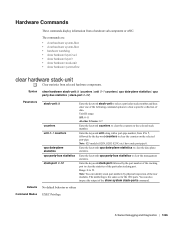
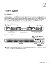
2 The S55 System Introduction The Dell Force10 S55 is a high performance, high capacity, low cost, stackable, Layer 2 switch/Layer 3 router that supports 44 built-in Figure 2-2, the S55's I /O Optional Module slots Power Supply (PSU1) RJ-45 USB-B Port Alarm LEDs Console Port Stack ID Grounding Ethernet Ports...As shown in 10/100/1000 Base-T ports, four SFP (small form-factor pluggable) ports, and two optional module slots, and optional 12G stacking module. The S55 I /O (Input/Output) side contains the 44 Ethernet ports, the SFP ports, the management ports and the displays...
2 The S55 System Introduction The Dell Force10 S55 is a high performance, high capacity, low cost, stackable, Layer 2 switch/Layer 3 router that supports 44 built-in Figure 2-2, the S55's I /O Optional Module slots Power Supply (PSU1) RJ-45 USB-B Port Alarm LEDs Console Port Stack ID Grounding Ethernet Ports...As shown in 10/100/1000 Base-T ports, four SFP (small form-factor pluggable) ports, and two optional module slots, and optional 12G stacking module. The S55 I /O (Input/Output) side contains the 44 Ethernet ports, the SFP ports, the management ports and the displays...
Installing the S55 System
Page 8
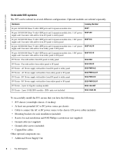
...S55-FAN S55 Series - www.dell.com | support.dell.com Orderable S55 systems The S55 can be ordered in several different configurations. AC Power supply with airflow from I/O panel to I/O panel S55-PWR-AC-R S55 Series - Hardware Catalog Number 44 port 10/100/1000 Base-T with 4 SFP ports and 2 expansion module slots S55T... ports and 2 expansion module slots, 1 AC power S55T-AC-R supply and 2 fan units with airflow from utility panel to I /O panel S55-PWR-DC-R S55 Series - 2 port 12 Gigabit stacking module S55-12G-2ST S55 Series - 2 port 10 GE SFP+ module - Fan with airflow from...
...S55-FAN S55 Series - www.dell.com | support.dell.com Orderable S55 systems The S55 can be ordered in several different configurations. AC Power supply with airflow from I/O panel to I/O panel S55-PWR-AC-R S55 Series - Hardware Catalog Number 44 port 10/100/1000 Base-T with 4 SFP ports and 2 expansion module slots S55T... ports and 2 expansion module slots, 1 AC power S55T-AC-R supply and 2 fan units with airflow from utility panel to I /O panel S55-PWR-DC-R S55 Series - 2 port 12 Gigabit stacking module S55-12G-2ST S55 Series - 2 port 10 GE SFP+ module - Fan with airflow from...
Installing the S55 System
Page 9
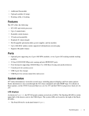
... supporting two 2-port 10G SFP+ modules, or two 2-port 12G stacking module stacking modules • 44 fixed 10/100/1000 Mbps auto-sensing and auto MDIX RJ45 ports • Four fixed ports supporting 100/1000 Base-T or 1000 Base-X using ) • Stacking cables, if stacking Features The S55 offers the following: • S55 CPU and switch processor • Up...
... supporting two 2-port 10G SFP+ modules, or two 2-port 12G stacking module stacking modules • 44 fixed 10/100/1000 Mbps auto-sensing and auto MDIX RJ45 ports • Four fixed ports supporting 100/1000 Base-T or 1000 Base-X using ) • Stacking cables, if stacking Features The S55 offers the following: • S55 CPU and switch processor • Up...
Installing the S55 System
Page 10
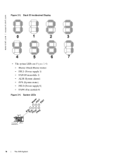
System LEDs MasterPSU1 FAN1 Alarm LEDs Stack ID Grounding ALMSYSPSU0FAN0 10/100/1000 USB-A Port Management Port 10 | The S55 System Stack ID hexidecimal Display • The system LEDs are (Figure 2-4): • Master (Stack Master status) • PSU1 (Power supply 1) • FAN1(Fan module 1) • ALM (System alarms) • SYS (System status) • PSU0 (Power supply 0) • FAN0 (Fan module 0) Figure 2-4. www.dell.com | support.dell.com Figure 2-3.
System LEDs MasterPSU1 FAN1 Alarm LEDs Stack ID Grounding ALMSYSPSU0FAN0 10/100/1000 USB-A Port Management Port 10 | The S55 System Stack ID hexidecimal Display • The system LEDs are (Figure 2-4): • Master (Stack Master status) • PSU1 (Power supply 1) • FAN1(Fan module 1) • ALM (System alarms) • SYS (System status) • PSU0 (Power supply 0) • FAN0 (Fan module 0) Figure 2-4. www.dell.com | support.dell.com Figure 2-3.
Installing the S55 System
Page 11
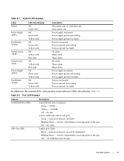
...) Fan Module (FAN0) LED Color/Display Off Green solid Off Green solid Yellow solid Off Green solid Yellow solid Off Yellow solid Red solid Off Yellow solid Red solid Off Green solid Yellow solid Off Green solid Yellow solid Description Non-master unit, or stand-alone unit Stack master unit... - 10/100M Off -No link Activity LED (right side of each port has status indicator LEDs, described in Table 2-2. Link up on this port The S55 System | 11 Off -No traffic Link/Activity LED Green - No Link detected at this port. Table 2-1. Off - Table 2-2. Activity, transmitting or receiving ...
...) Fan Module (FAN0) LED Color/Display Off Green solid Off Green solid Yellow solid Off Green solid Yellow solid Off Yellow solid Red solid Off Yellow solid Red solid Off Green solid Yellow solid Off Green solid Yellow solid Description Non-master unit, or stand-alone unit Stack master unit... - 10/100M Off -No link Activity LED (right side of each port has status indicator LEDs, described in Table 2-2. Link up on this port The S55 System | 11 Off -No traffic Link/Activity LED Green - No Link detected at this port. Table 2-1. Off - Table 2-2. Activity, transmitting or receiving ...
Installing the S55 System
Page 17
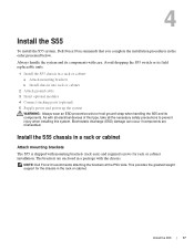
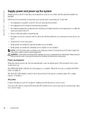
... brackets b Install chassis into rack or cabinet 2 Attach ground cable 3 Insert optional modules 4 Connect stacking ports (optional) 5 Supply power and power up the system WARNING: Always wear an ESD-preventive wrist or heel ground strap when handling the S55 and its components. NOTE: Dell Force10 recommends attaching the brackets at the PSU side. Install the...
... brackets b Install chassis into rack or cabinet 2 Attach ground cable 3 Insert optional modules 4 Connect stacking ports (optional) 5 Supply power and power up the system WARNING: Always wear an ESD-preventive wrist or heel ground strap when handling the S55 and its components. NOTE: Dell Force10 recommends attaching the brackets at the PSU side. Install the...
Installing the S55 System
Page 20
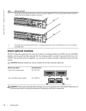
...; CAUTION: Stacking modules can occur if components are mishandled. Module Description 2-port 12G stacking module Catalog Number S55-12G-2ST 2-port 10G SFP+ optical module S55-10GE-2S WARNING: Electrostatic discharge (ESD) damage can only be torqued to the chassis as shown, using the supplied 10-32 screw with captive internal tooth lock washer. www.dell.com | support.dell.com...
...; CAUTION: Stacking modules can occur if components are mishandled. Module Description 2-port 12G stacking module Catalog Number S55-12G-2ST 2-port 10G SFP+ optical module S55-10GE-2S WARNING: Electrostatic discharge (ESD) damage can only be torqued to the chassis as shown, using the supplied 10-32 screw with captive internal tooth lock washer. www.dell.com | support.dell.com...
Installing the S55 System
Page 21
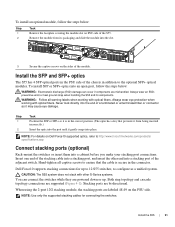
...a cabinet before you make your stacking port connections. CAUTION: The S55 system does not stack with other end into a stacking port of the chassis in the connector. NOTE: For details on the PSU side. Dell Force10 supports stacking connections for connecting the switches. ...Both ring topology and cascade topology connections are bi-directional. Always wear eye protection when working with optical fibers. Install the S55 | 21 To install an optional module, follow the steps below...
...a cabinet before you make your stacking port connections. CAUTION: The S55 system does not stack with other end into a stacking port of the chassis in the connector. NOTE: For details on the PSU side. Dell Force10 supports stacking connections for connecting the switches. ...Both ring topology and cascade topology connections are bi-directional. Always wear eye protection when working with optical fibers. Install the S55 | 21 To install an optional module, follow the steps below...
Installing the S55 System
Page 22
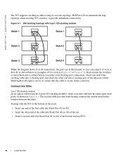
....dell.com The S55 supports stacking in Figure 4-2. Dell Force10 recommends the ring topology when stacking S55 switches, to ensure that the cable is secure in examples of the adjacent switch. Figure 4-1. Rack-mount the switches or insert them into Stack Port 49 (or 48) of the bottom and top S55s. 22 | Install the S55 Starting with 2-port 12G stacking module Switch...
....dell.com The S55 supports stacking in Figure 4-2. Dell Force10 recommends the ring topology when stacking S55 switches, to ensure that the cable is secure in examples of the adjacent switch. Figure 4-1. Rack-mount the switches or insert them into Stack Port 49 (or 48) of the bottom and top S55s. 22 | Install the S55 Starting with 2-port 12G stacking module Switch...
Installing the S55 System
Page 23
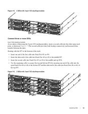
... 12G stacking modules Connect three or more S55s 2-port 12G stacking modules As an option, when using the 2-port 12G stacking modules, insert a second cable into the other end of the cable into the open Stack Port 49 (or 48) of the bottom S55 and the other open stack ports, as shown in Figure 4-3. Figure 4-3. 3 S55s with 2-port 12G stacking modules Install the S55...
... 12G stacking modules Connect three or more S55s 2-port 12G stacking modules As an option, when using the 2-port 12G stacking modules, insert a second cable into the other end of the cable into the open Stack Port 49 (or 48) of the bottom S55 and the other open stack ports, as shown in Figure 4-3. Figure 4-3. 3 S55s with 2-port 12G stacking modules Install the S55...
Installing the S55 System
Page 24
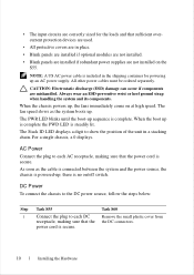
... is properly secured to show the position of the unit in a rack (or on a table) and the optional modules are mishandled. Dell Force10 recommends re-inspecting your system prior to the S55 after they are mounted in a stacking chain. WARNING: Electrostatic discharge (ESD) damage can occur if components are installed. For a single chassis, a 0 displays. When...
... is properly secured to show the position of the unit in a rack (or on a table) and the optional modules are mishandled. Dell Force10 recommends re-inspecting your system prior to the S55 after they are mounted in a stacking chain. WARNING: Electrostatic discharge (ESD) damage can occur if components are installed. For a single chassis, a 0 displays. When...
Quick Start Guide
Page 12
... the fans immediately come on at high speed. power cord is included in a stacking chain. Always wear an ESD-preventive wrist or heel ground strap when handling the ... to the DC power source, follow the steps below: Step Task S55 Task S60 1 Connect the plug to show the position of the ...is powered-up is complete the PWD LED is no on the S55. When the boot up ; All other power cables must be ordered separately...NOTE: A US AC power cable is secure. 10 Installing the Hardware The Stack ID LED displays a digit to each AC receptacle, making sure that sufficient overcurrent...
... the fans immediately come on at high speed. power cord is included in a stacking chain. Always wear an ESD-preventive wrist or heel ground strap when handling the ... to the DC power source, follow the steps below: Step Task S55 Task S60 1 Connect the plug to show the position of the ...is powered-up is complete the PWD LED is no on the S55. When the boot up ; All other power cables must be ordered separately...NOTE: A US AC power cable is secure. 10 Installing the Hardware The Stack ID LED displays a digit to each AC receptacle, making sure that sufficient overcurrent...
S55 Configuration Guide FTOS 8.3.5.3
Page 722
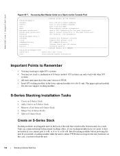
...; Split an S-Series Stack Create an S-Series Stack Stacking modules are connected using bi-directional stacking cables; S-Series Stacking Installation Tasks • Create an S-Series Stack • Add a Unit to eight S55s systems. • You may not stack a combination of the unit that switch traffic between units in this unit alone show ? www.dell.com | support.dell.com Figure 40-7. calendar...
...; Split an S-Series Stack Create an S-Series Stack Stacking modules are connected using bi-directional stacking cables; S-Series Stacking Installation Tasks • Create an S-Series Stack • Add a Unit to eight S55s systems. • You may not stack a combination of the unit that switch traffic between units in this unit alone show ? www.dell.com | support.dell.com Figure 40-7. calendar...
S55 Configuration Guide FTOS 8.3.5.3
Page 723
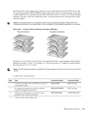
... topology supported by your system type to make management unit selection deterministic. Note: The S55 stacking modules are numbered from left to an existing stack: Step 1 2 3 4 Task Verify that the stacking is an example to stacking them with two 12-Gigabyte stacking modules, the stack-ports are 49, 50, 51, and 52. To add a unit to right, beginning with...
... topology supported by your system type to make management unit selection deterministic. Note: The S55 stacking modules are numbered from left to an existing stack: Step 1 2 3 4 Task Verify that the stacking is an example to stacking them with two 12-Gigabyte stacking modules, the stack-ports are 49, 50, 51, and 52. To add a unit to right, beginning with...
S55 Configuration Guide FTOS 8.3.5.3
Page 724
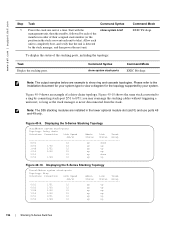
...your system. Figure 40-9 shows an example of their assigned stack number (or the position in the lower optional module slot (slot 0) and use ports 48 and 49 only. Figure 40-9. Displaying the S-Series Stacking Topology Force10#show ring and cascade topologies. Allow each unit to show system...up up Figure 40-10. Note: The S55 stacking modules are example to completely boot, and verify that the unit is never disconnected from the stack. you want each of the members in order of a daisy-chain topology. www.dell.com | support.dell.com Step 5 Task Command Syntax Power the...
...your system. Figure 40-9 shows an example of their assigned stack number (or the position in the lower optional module slot (slot 0) and use ports 48 and 49 only. Figure 40-9. Displaying the S-Series Stacking Topology Force10#show ring and cascade topologies. Allow each unit to show system...up up Figure 40-10. Note: The S55 stacking modules are example to completely boot, and verify that the unit is never disconnected from the stack. you want each of the members in order of a daisy-chain topology. www.dell.com | support.dell.com Step 5 Task Command Syntax Power the...


