
FTOS Command Line Reference Guide for the S4810 System FTOS 9.1.(0.0)
Page 153
Fan Status Unit TrayStatus Fan0 Fan1 Fan2 Fan3 Fan4 Fan5 0 up up up up up up up AC 0 1 absent -- Power Supplies -Unit Bay Status Type 0 0 up -- Fan Status Unit TrayStatus Fan0 Fan1 Fan2 Fan3 Fan4 Fan5 0 up up up up up up up ... for the S-Series. Fan Status -Unit Status Speed Fan1 Fan2 Fan3 Fan4 Fan5 Fan6 Serial Num Version 1 up high up up up up up up AC 0 1 absent FTOS#show environment fan command as it appears prior to FTOS 7.8.1.0. The example below shows the output of the show environment stack-unit 0 -- S-Series...
Fan Status Unit TrayStatus Fan0 Fan1 Fan2 Fan3 Fan4 Fan5 0 up up up up up up up AC 0 1 absent -- Power Supplies -Unit Bay Status Type 0 0 up -- Fan Status Unit TrayStatus Fan0 Fan1 Fan2 Fan3 Fan4 Fan5 0 up up up up up up up ... for the S-Series. Fan Status -Unit Status Speed Fan1 Fan2 Fan3 Fan4 Fan5 Fan6 Serial Num Version 1 up high up up up up up up AC 0 1 absent FTOS#show environment fan command as it appears prior to FTOS 7.8.1.0. The example below shows the output of the show environment stack-unit 0 -- S-Series...

FTOS Command Line Reference Guide for the S4810 System FTOS 9.1.(0.0)
Page 155
... (E300) Example (media slot) Example (inventory) C300 TY000001400 7520029999 04 3 LC-CB-GE-48T FX000020075 7520036700 01 0 LC-CB-RPM 0060361 7520029300 02 0 CC-C-1200W-AC N/A N/A N/A 1 CC-C-1200W-AC N/A N/A N/A 0 CC-C300-FAN * -
... (E300) Example (media slot) Example (inventory) C300 TY000001400 7520029999 04 3 LC-CB-GE-48T FX000020075 7520036700 01 0 LC-CB-RPM 0060361 7520029300 02 0 CC-C-1200W-AC N/A N/A N/A 1 CC-C-1200W-AC N/A N/A N/A 0 CC-C300-FAN * -

FTOS Command Line Reference Guide for the S4810 System FTOS 9.1.(0.0)
Page 157
...0a Unit Type Serial Number Part Number Revision 0 *S50-01-GE-48T-V DL267050013 7590003600 B 0 S50-01-10GE-2C N/A N/A N/A 0 S50-PWR-AC N/A N/A N/A 0 S50-FAN N/A N/A N/A * - The output also displays the transceiver's serial number. 157 displays the interface configuration. • show... Unit Type Serial Number Part Number Rev Piece Part ID Ver Service Tag * 0 Z9000-01-40GE-AC Z8FX113100314 7520052401 MY-08R4VK-75412-1BA-0474 A00 ABC1234 0 Z9000-PWR-AC N/A N/A N/A N/A 0 Z9000-FAN Z5FX112500170 7520051702 MY-08R4VK-75412-1BA-0474 A00 ABC1234 0 Z9000-...
...0a Unit Type Serial Number Part Number Revision 0 *S50-01-GE-48T-V DL267050013 7590003600 B 0 S50-01-10GE-2C N/A N/A N/A 0 S50-PWR-AC N/A N/A N/A 0 S50-FAN N/A N/A N/A * - The output also displays the transceiver's serial number. 157 displays the interface configuration. • show... Unit Type Serial Number Part Number Rev Piece Part ID Ver Service Tag * 0 Z9000-01-40GE-AC Z8FX113100314 7520052401 MY-08R4VK-75412-1BA-0474 A00 ABC1234 0 Z9000-PWR-AC N/A N/A N/A N/A 0 Z9000-FAN Z5FX112500170 7520051702 MY-08R4VK-75412-1BA-0474 A00 ABC1234 0 Z9000-...
FTOS Command Line Reference Guide for the S4810 System FTOS 9.1.(0.0)
Page 159
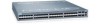
... 159 Displays the two possible Bootflash versions. Displays the line card serial number. Displays an internal code, which version was used in the chassis: • AC = AC power supply • DC = DC Power Entry Module (PEM) Voltage Serial Number Part Num Vendor ID Date Code Displays OK if the line voltage is...
... 159 Displays the two possible Bootflash versions. Displays the line card serial number. Displays an internal code, which version was used in the chassis: • AC = AC power supply • DC = DC Power Entry Module (PEM) Voltage Serial Number Part Num Vendor ID Date Code Displays OK if the line voltage is...
FTOS Command Line Reference Guide for the S4810 System FTOS 9.1.(0.0)
Page 185
... not present -- Example Example (Z9000) Version 8.3.11.1 Version 7.8.1.0 Version 7.7.1.0 Version 7.6.1.0 Modified the show system brief Stack MAC : 0:1:e8:d6:4:70 -- Unit Bay Status Type ---------- -- 1 0 up AC 1 1 absent ct-z9000-2#show system stack-unit 0 -- Unit 0 -Unit Type Status Next Boot Required Type Current Type Master priority Hardware Rev Num Ports Up Time...
... not present -- Example Example (Z9000) Version 8.3.11.1 Version 7.8.1.0 Version 7.7.1.0 Version 7.6.1.0 Modified the show system brief Stack MAC : 0:1:e8:d6:4:70 -- Unit Bay Status Type ---------- -- 1 0 up AC 1 1 absent ct-z9000-2#show system stack-unit 0 -- Unit 0 -Unit Type Status Next Boot Required Type Current Type Master priority Hardware Rev Num Ports Up Time...

FTOS Command Line Reference Guide for the S4810 System FTOS 9.1.(0.0)
Page 187
...), enter one of text. displays the memory usage based on running processes. • show commands, the information necessary for Dell Force10 technical support to perform troubleshooting. show tech-support (C-Series and E-Series) Display, or save to a file, a collection...Modes Command History Usage Information EXEC Privilege Version 7.8.1.0 Version 7.5.1.0 Version 6.5.4.0 Introduced save to interrupt the command output. 187 Related Commands -- 0 0 up AC • show tech-support [linecard 0-6 | page] | {display | except | find | grep | no-more | save} linecard 0-6 page display...
...), enter one of text. displays the memory usage based on running processes. • show commands, the information necessary for Dell Force10 technical support to perform troubleshooting. show tech-support (C-Series and E-Series) Display, or save to a file, a collection...Modes Command History Usage Information EXEC Privilege Version 7.8.1.0 Version 7.5.1.0 Version 6.5.4.0 Introduced save to interrupt the command output. 187 Related Commands -- 0 0 up AC • show tech-support [linecard 0-6 | page] | {display | except | find | grep | no-more | save} linecard 0-6 page display...

FTOS Command Line Reference Guide for the S4810 System FTOS 9.1.(0.0)
Page 578
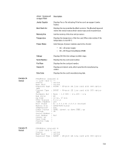
...-usage switch Linecard|Portpipe|CAM Partition|Total CAM|Used CAM|AvailableCAM 11 | 0 |IN-L2 ACL | 7152 | 0| 7152 | |IN-L2 FIB | 32768 | 1081| 31687 | |OUT-L2 AC | 0 | 0| 0 11 | 1 |IN-L2 ACL | 7152 | 0| 7152 | |IN-L2 FIB | 32768 | 1081| 31687 | |OUT-L2 ACL | 0 | 0| 0 FTOS# FTOS#show cam-usage Linecard|Portpipe|CAM Partition |Total...
...-usage switch Linecard|Portpipe|CAM Partition|Total CAM|Used CAM|AvailableCAM 11 | 0 |IN-L2 ACL | 7152 | 0| 7152 | |IN-L2 FIB | 32768 | 1081| 31687 | |OUT-L2 AC | 0 | 0| 0 11 | 1 |IN-L2 ACL | 7152 | 0| 7152 | |IN-L2 FIB | 32768 | 1081| 31687 | |OUT-L2 ACL | 0 | 0| 0 FTOS# FTOS#show cam-usage Linecard|Portpipe|CAM Partition |Total...

Installing the S4820T System
Page 3
... S4820T Unpacking the S4820T Switch 21 Package Contents 21 Unpacking Steps 22 Installing Rack or Cabinet Hardware 23 Rack Mounting Safety Considerations 23 Installing the Dell ReadyRails System 24 Two-post Flush-mount Configuration 25 Two-post Center-mount Configuration 26 Four-post Threaded Configuration 27 Installing the S4820T Switch 28...
... S4820T Unpacking the S4820T Switch 21 Package Contents 21 Unpacking Steps 22 Installing Rack or Cabinet Hardware 23 Rack Mounting Safety Considerations 23 Installing the Dell ReadyRails System 24 Two-post Flush-mount Configuration 25 Two-post Center-mount Configuration 26 Four-post Threaded Configuration 27 Installing the S4820T Switch 28...

Installing the S4820T System
Page 4
www.dell.com | support.dell.com 4| Removing QSFP+ Optics 31 Splitting QSFP+ Ports to SFP+ or...Systems 35 Hot-Swapping Units in a Stack 36 5 Power Supplies Components 39 Installing an AC or DC Power Supply 40 Replacing an AC or DC Power Supply 40 Connecting a DC Power Supply to the Power Source 41 ... Port (RS-232 45 Default Configuration 46 8 Specifications Chassis Physical Design 47 Environmental Parameters 47 Power Requirements 48 AC Input Specification 48 DC Input Specification 48 IEEE Standards 48 Agency Compliance 49 Network Equipment Building Systems (NEBS) Compliance...
www.dell.com | support.dell.com 4| Removing QSFP+ Optics 31 Splitting QSFP+ Ports to SFP+ or...Systems 35 Hot-Swapping Units in a Stack 36 5 Power Supplies Components 39 Installing an AC or DC Power Supply 40 Replacing an AC or DC Power Supply 40 Connecting a DC Power Supply to the Power Source 41 ... Port (RS-232 45 Default Configuration 46 8 Specifications Chassis Physical Design 47 Environmental Parameters 47 Power Requirements 48 AC Input Specification 48 DC Input Specification 48 IEEE Standards 48 Agency Compliance 49 Network Equipment Building Systems (NEBS) Compliance...

Installing the S4820T System
Page 14
www.dell.com | support.dell.com Basic Installation Requirements Detailed installation instructions for the S4820T are provided in Chapter 3, Site Location and Preparation and Chapter 4, Installing the S4820T, however, the ... required for a successful installation of the S4820T: • S4820T chassis (or multiple chassis, if stacking) • If you ordered AC units, cables to connect the AC power source to each of the chassis' AC power supplies (country/regional configured) • If you ordered DC units, cables to connect the DC power source to...
www.dell.com | support.dell.com Basic Installation Requirements Detailed installation instructions for the S4820T are provided in Chapter 3, Site Location and Preparation and Chapter 4, Installing the S4820T, however, the ... required for a successful installation of the S4820T: • S4820T chassis (or multiple chassis, if stacking) • If you ordered AC units, cables to connect the AC power source to each of the chassis' AC power supplies (country/regional configured) • If you ordered DC units, cables to connect the DC power source to...

Installing the S4820T System
Page 15
... Airflow: 48 port 10G RJ-45 ports with 4 QSFP+ 40G ports, 1 DC power supply and 2 fan subsystems (airflow from I/O side to power supply side) S4820T AC Reverse Airflow: 48 port 10G RJ-45 ports with 4 QSFP+ 40G ports, 1 DC power supply and 2 fan subsystems (airflow from power supply side to I/O side... with airflow from the I/O side to the PSU side Fan with airflow from the PSU side to the I/O side AC Power supply with airflow from the I/O side to the PSU side AC Power supply with airflow from the PSU side to the I/O side DC Power supply with airflow from the I/O side to...
... Airflow: 48 port 10G RJ-45 ports with 4 QSFP+ 40G ports, 1 DC power supply and 2 fan subsystems (airflow from I/O side to power supply side) S4820T AC Reverse Airflow: 48 port 10G RJ-45 ports with 4 QSFP+ 40G ports, 1 DC power supply and 2 fan subsystems (airflow from power supply side to I/O side... with airflow from the I/O side to the PSU side Fan with airflow from the PSU side to the I/O side AC Power supply with airflow from the I/O side to the PSU side AC Power supply with airflow from the PSU side to the I/O side DC Power supply with airflow from the I/O side to...

Installing the S4820T System
Page 19
... of the National Electrical Code, ANSI/NFPA 70 where applicable. Storing Components If you do not install your S4820T and components immediately, Dell Force10 recommends properly storing the system and all optional components until you install two S4820T systems near the equipment and is done as the main ... Guide for the S4820T System. Use the show logging command to the applicable power source. • If the switch is an AC model, an AC power cord (country/region specific) is included with the system. Power Use the appropriate power cord with the S4820T system to connect...
... of the National Electrical Code, ANSI/NFPA 70 where applicable. Storing Components If you do not install your S4820T and components immediately, Dell Force10 recommends properly storing the system and all optional components until you install two S4820T systems near the equipment and is done as the main ... Guide for the S4820T System. Use the show logging command to the applicable power source. • If the switch is an AC model, an AC power cord (country/region specific) is included with the system. Power Use the appropriate power cord with the S4820T system to connect...

Installing the S4820T System
Page 21
...each S4820T switch, make sure that the following items are mishandled. 4 Installing the S4820T To install the S4820T system, Dell Force10 recommends completing the installation procedures in the order presented in this system. Unpacking the S4820T Switch NOTE: Before unpacking the ...mount Configuration d Four-post Threaded Configuration 3 Installing the S4820T Switch a 1U Front-rack Installation b Attaching the Ground Cable c Installing an AC or DC Power Supply 4 Installing QSFP+ Optics 5 Connecting the Stacking Ports (Optional) 6 Powering Up the S4820T Switch WARNING: Electrostatic ...
...each S4820T switch, make sure that the following items are mishandled. 4 Installing the S4820T To install the S4820T system, Dell Force10 recommends completing the installation procedures in the order presented in this system. Unpacking the S4820T Switch NOTE: Before unpacking the ...mount Configuration d Four-post Threaded Configuration 3 Installing the S4820T Switch a 1U Front-rack Installation b Attaching the Ground Cable c Installing an AC or DC Power Supply 4 Installing QSFP+ Optics 5 Connecting the Stacking Ports (Optional) 6 Powering Up the S4820T Switch WARNING: Electrostatic ...

Installing the S4820T System
Page 22
www.dell.com | support.dell.com • At least one PSU • If an AC switch, at least one AC power cord (country/region specific) • If a DC switch, at least one DC power cable • Getting Started Guide • Safety and Regulatory Information • ...
www.dell.com | support.dell.com • At least one PSU • If an AC switch, at least one AC power cord (country/region specific) • If a DC switch, at least one DC power cable • Getting Started Guide • Safety and Regulatory Information • ...

Installing the S4820T System
Page 29
...slides into a slot as the blank plate slot. To install an AC or DC power supply, follow these steps: Installing the S4820T | 29 Dell Force10 recommends using power supply 1 (PSU1) as this may result. Installing an AC or DC Power Supply The S4820T supports two hot-swappable power supplies ...must be clean and free from contamination. 1 Take the one -hole lug with a single PSU. You cannot replace an AC PSU with the captive internal tooth lock washer. Dell Force10 recommends using the supplied 10-32 screw with a DC PSU and you do not ground your local electrical requirements.
...slides into a slot as the blank plate slot. To install an AC or DC power supply, follow these steps: Installing the S4820T | 29 Dell Force10 recommends using power supply 1 (PSU1) as this may result. Installing an AC or DC Power Supply The S4820T supports two hot-swappable power supplies ...must be clean and free from contamination. 1 Take the one -hole lug with a single PSU. You cannot replace an AC PSU with the captive internal tooth lock washer. Dell Force10 recommends using the supplied 10-32 screw with a DC PSU and you do not ground your local electrical requirements.
Installing the S4820T System
Page 30
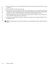
... is keyed such that the PSU can only be fully inserted in the appropriate cord (AC 3 prong or DC wiring) from the electrostatic bag. 3 Insert the PSU into place... the cables are connected between the power supply and the power source. 30 | Installing the S4820T www.dell.com | support.dell.com 1 Remove the PSU slot cover from the S4820T (PSU side of switch), either of the two... PSU slots may be selected. 2 Remove the PSU from the switch PSU to the external power source (either AC wall outlet...
... is keyed such that the PSU can only be fully inserted in the appropriate cord (AC 3 prong or DC wiring) from the electrostatic bag. 3 Insert the PSU into place... the cables are connected between the power supply and the power source. 30 | Installing the S4820T www.dell.com | support.dell.com 1 Remove the PSU slot cover from the S4820T (PSU side of switch), either of the two... PSU slots may be selected. 2 Remove the PSU from the switch PSU to the external power source (either AC wall outlet...

Installing the S4820T System
Page 39
... PSU slot. The S4820T supports AC power supplies with a DC-R PSU. WARNING: Electrostatic discharge (ESD) damage can remove and replace one PSU without disrupting traffic. Components The following power supply options are required for the system. Dell Force10 recommends using power supply 1 (...PSU1) as the blank plate slot. S4820T with full redundancy (two power supplies installed and running with One AC PSU Power Supply 0 Power Supply 1 Port Power Supplies |...
... PSU slot. The S4820T supports AC power supplies with a DC-R PSU. WARNING: Electrostatic discharge (ESD) damage can remove and replace one PSU without disrupting traffic. Components The following power supply options are required for the system. Dell Force10 recommends using power supply 1 (...PSU1) as the blank plate slot. S4820T with full redundancy (two power supplies installed and running with One AC PSU Power Supply 0 Power Supply 1 Port Power Supplies |...

Installing the S4820T System
Page 40
...not connect the power cable before you must replace the entire PSU. Dell Force10 recommends using power supply 1 (PSU1) as this may damage the PSU or the S4820T chassis. Installing an AC or DC Power Supply To install an AC or DC power supply, follow these steps: NOTE: The PSU slides... from the PSU prior to Chapter 6, Fans. Replacing an AC or DC Power Supply NOTE: The PSU slides into the slot smoothly. www.dell.com | support.dell.com The PSUs are in the other PSU slot. To ensure sufficient room, Dell Force10 recommends using power supply 1 (PSU1) as this may damage...
...not connect the power cable before you must replace the entire PSU. Dell Force10 recommends using power supply 1 (PSU1) as this may damage the PSU or the S4820T chassis. Installing an AC or DC Power Supply To install an AC or DC power supply, follow these steps: NOTE: The PSU slides... from the PSU prior to Chapter 6, Fans. Replacing an AC or DC Power Supply NOTE: The PSU slides into the slot smoothly. www.dell.com | support.dell.com The PSUs are in the other PSU slot. To ensure sufficient room, Dell Force10 recommends using power supply 1 (PSU1) as this may damage...

Installing the S4820T System
Page 41
... to slide the PSU out of the power supply bay. 4 Use the grab handle on the replacement PSU to the replacement PSU. To replace an AC or DC power supply, follow these steps: Step Task 1 Disconnect the power cable from the PSU. 2 Loosen the securing screws on the replacement PSU with...
... to slide the PSU out of the power supply bay. 4 Use the grab handle on the replacement PSU to the replacement PSU. To replace an AC or DC power supply, follow these steps: Step Task 1 Disconnect the power cable from the PSU. 2 Loosen the securing screws on the replacement PSU with...

Installing the S4820T System
Page 43
... system, both slots must have operating fan units. If the airflow directions are hot-swappable. Check the environmental factors regularly. S4820T Fan Modules and One AC PSU Power Supply 0 with with one minute. • Normal-airflow is from the I /O panel Environmental factors can use only a single airflow direction in one minute...
... system, both slots must have operating fan units. If the airflow directions are hot-swappable. Check the environmental factors regularly. S4820T Fan Modules and One AC PSU Power Supply 0 with with one minute. • Normal-airflow is from the I /O panel Environmental factors can use only a single airflow direction in one minute...


