Installing the S25P System
Page 9
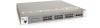
... CX4), in the rear panel (Figure 2). Chapter 1 S25P System Overview The Force10 Networks S25P (Cat# S25-01-GE-24P) is a high performance, low cost, stackable, Layer 2 switch/Layer 3 router that displays activity of the S25P-DC, see Connecting Stack Ports (optional) on the S25P-DC (cat.# S25-01-GE-24P-DC). Figure 1 The S25P (Front View) Stack ID Indicator LED Status Panel...
... CX4), in the rear panel (Figure 2). Chapter 1 S25P System Overview The Force10 Networks S25P (Cat# S25-01-GE-24P) is a high performance, low cost, stackable, Layer 2 switch/Layer 3 router that displays activity of the S25P-DC, see Connecting Stack Ports (optional) on the S25P-DC (cat.# S25-01-GE-24P-DC). Figure 1 The S25P (Front View) Stack ID Indicator LED Status Panel...
Installing the S25P System
Page 17
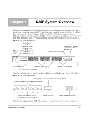
... discharge (ESD) damage can occur if components are only using one XFP or CX4 module, insert it in the use of stack port). S25P-DC on page 25. The ports are numbered 25 through 28, from left -most expansion slot. See Connecting Stack Ports (optional) on page 28 ... S25P system, Force10 Networks recommends that you face the front of the chassis. Always wear an ESD-preventive wrist or heel ground strap when handling the S25P and its components. Installing the S25P System 17 Inserting Optional Modules (10-Gigabit or Stacking) The S25P (catalog name S25-01-GE-24P) has two ...
... discharge (ESD) damage can occur if components are only using one XFP or CX4 module, insert it in the use of stack port). S25P-DC on page 25. The ports are numbered 25 through 28, from left -most expansion slot. See Connecting Stack Ports (optional) on page 28 ... S25P system, Force10 Networks recommends that you face the front of the chassis. Always wear an ESD-preventive wrist or heel ground strap when handling the S25P and its components. Installing the S25P System 17 Inserting Optional Modules (10-Gigabit or Stacking) The S25P (catalog name S25-01-GE-24P) has two ...
Installing the S25P System
Page 28
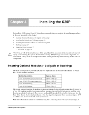
.... Ensure that the remote power source (the circuit breaker panel) is on page 15), the S25P-DC (cat. S25P-DC As shown below (see Power Requirements on page 34). name S25-01-GE-24P-DC) has two DC terminal blocks on the DC terminal blocks. 6 If you are connecting both terminal blocks, do not supply power until both . You...
.... Ensure that the remote power source (the circuit breaker panel) is on page 15), the S25P-DC (cat. S25P-DC As shown below (see Power Requirements on page 34). name S25-01-GE-24P-DC) has two DC terminal blocks on the DC terminal blocks. 6 If you are connecting both terminal blocks, do not supply power until both . You...
Installing the S25P System
Page 47
... a unit from a stack 25 removing battery 37 requesting replacement hardware 43 RJ-45 installation 29 S S25-01-GE-48P (S25P catalog name) 17 S25P front view 9 S25P rear view 9 S25P status information 11 S25P switch catalog name 9 S25P-DC 9 S50V front view 15, 28 S50V rear view 15 Safety Standards 36 screws for rack...
... a unit from a stack 25 removing battery 37 requesting replacement hardware 43 RJ-45 installation 29 S S25-01-GE-48P (S25P catalog name) 17 S25P front view 9 S25P rear view 9 S25P status information 11 S25P switch catalog name 9 S25P-DC 9 S50V front view 15, 28 S50V rear view 15 Safety Standards 36 screws for rack...

