
Dell Force10 E300, E600i, and E1200i Systems Quick Start Guide
Page 13
...type of power module-AC or DC. Installing Power Modules This section provides instructions to the nearest appropriate facility grounding post. E300 AC Power Modules The E300 system requires a minimum of the grounding cable to install AC Power Supply Units (PSUs) and DC Power Entry Modules (... 5 With a 7/16-inch box or socket wrench, tighten the nuts (torque should be terminated only with a ULlisted 2-hole lug with a Dell Force10-approved power cord and only that the power cables meet your local electrical codes in each E-Series system. WARNING: To prevent electrical shock, make ...
...type of power module-AC or DC. Installing Power Modules This section provides instructions to the nearest appropriate facility grounding post. E300 AC Power Modules The E300 system requires a minimum of the grounding cable to install AC Power Supply Units (PSUs) and DC Power Entry Modules (... 5 With a 7/16-inch box or socket wrench, tighten the nuts (torque should be terminated only with a ULlisted 2-hole lug with a Dell Force10-approved power cord and only that the power cables meet your local electrical codes in each E-Series system. WARNING: To prevent electrical shock, make ...

FTOS Command Line Reference Guide FTOS 8.4.2.8 E-Series TeraScale
Page 52
...-image to change the bootflash image on the RPM. 52 | File Management www.dell.com | support.dell.com show version Force10 Networks Real Time Operating System Software Force10 Operating System Version: 1.0 Force10 Application Software Version: E7-8-1-13 Copyright (c) 1999-2008 by the slot number to ...13 on the E1200; 0 to 6 for the E600; 0 to 5 on the E300 Enter the keyword rpm to upgrade the bootflash/boot selector image on a processor. Enter the keyword linecard followed by Force10 Networks, Inc. This keyword does not upgrade the bootflash on system. Use with 128K ...
...-image to change the bootflash image on the RPM. 52 | File Management www.dell.com | support.dell.com show version Force10 Networks Real Time Operating System Software Force10 Operating System Version: 1.0 Force10 Application Software Version: E7-8-1-13 Copyright (c) 1999-2008 by the slot number to ...13 on the E1200; 0 to 6 for the E600; 0 to 5 on the E300 Enter the keyword rpm to upgrade the bootflash/boot selector image on a processor. Enter the keyword linecard followed by Force10 Networks, Inc. This keyword does not upgrade the bootflash on system. Use with 128K ...
FTOS Command Line Reference Guide FTOS 8.4.2.8 E-Series TeraScale
Page 83
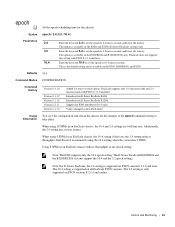
This option is available on the E300, E600/E600i, and E1200. This is the default setting and is line rate; When using 10 SFMs in an ExaScale chassis reduces throughput at any epoch setting. Dell Force10 recommends using 9 SFMs in an ExaScale chassis, the 10.4 setting is...supports only 10.4 microseconds and 2.4 microseconds with FTOS 8.3.1.0 and later. The 10.4 setting is only supported on E-Series ExaScale E1200i Support for E300 introduced (10.4 only) Values changed as described above Usage You save the configuration and reload the chassis for the chassis. Control and Monitoring ...
This option is available on the E300, E600/E600i, and E1200. This is the default setting and is line rate; When using 10 SFMs in an ExaScale chassis reduces throughput at any epoch setting. Dell Force10 recommends using 9 SFMs in an ExaScale chassis, the 10.4 setting is...supports only 10.4 microseconds and 2.4 microseconds with FTOS 8.3.1.0 and later. The 10.4 setting is only supported on E-Series ExaScale E1200i Support for E300 introduced (10.4 only) Values changed as described above Usage You save the configuration and reload the chassis for the chassis. Control and Monitoring ...

FTOS Command Line Reference Guide FTOS 8.4.2.8 E-Series TeraScale
Page 601
... interface. Related Commands show interfaces Display information on E-Series Usage The following figure shows a line card that is not certified by Dell Force10 is not set MTU 1554 bytes, IP MTU 1500 bytes LineSpeed 10000 Mbit ARP type: ARPA, ARP Timeout 04:00:00 Last...Enter a number for C150 E-Series Range: 0 to 13 on the E1200/1200i, 0 to 6 on the E600/600i, 0 to 5 on the E300 Command Modes EXEC EXEC Privilege Command History Version 8.1.1.2 Version 8.1.1.0 Version 7.5.1.0 pre-Version 6.2.1.1 Introduced support on E-Series ExaScale E600i Introduced on E-Series ExaScale Introduced ...
... interface. Related Commands show interfaces Display information on E-Series Usage The following figure shows a line card that is not certified by Dell Force10 is not set MTU 1554 bytes, IP MTU 1500 bytes LineSpeed 10000 Mbit ARP type: ARPA, ARP Timeout 04:00:00 Last...Enter a number for C150 E-Series Range: 0 to 13 on the E1200/1200i, 0 to 6 on the E600/600i, 0 to 5 on the E300 Command Modes EXEC EXEC Privilege Command History Version 8.1.1.2 Version 8.1.1.0 Version 7.5.1.0 pre-Version 6.2.1.1 Introduced support on E-Series ExaScale E600i Introduced on E-Series ExaScale Introduced ...

FTOS Command Line Reference Guide FTOS 8.4.2.8 E-Series TeraScale
Page 1546
...lp and the slot number to view information on a E300. type = 5 frrpaProcessIfmNotif(): Default case. When the buffer is automatically deleted to make room for the last command line).This file can be analyzed by the Dell Force10 Technical Assistance Center (TAC) to assist in that ... users, except password related commands, are the same (i.e. of each command and if the characters are captured in the display output. www.dell.com | support.dell.com • [by admin from vty0 (peer RPM)] -with "Repeated X times" (see Figure 65-5). type = 5 frrpaProcessIfmNotif(): ...
...lp and the slot number to view information on a E300. type = 5 frrpaProcessIfmNotif(): Default case. When the buffer is automatically deleted to make room for the last command line).This file can be analyzed by the Dell Force10 Technical Assistance Center (TAC) to assist in that ... users, except password related commands, are the same (i.e. of each command and if the characters are captured in the display output. www.dell.com | support.dell.com • [by admin from vty0 (peer RPM)] -with "Repeated X times" (see Figure 65-5). type = 5 frrpaProcessIfmNotif(): ...

FTOS Command Line Reference Guide FTOS 8.4.2.8 E-Series TeraScale
Page 1558
...on a E300. (OPTIONAL) Enter the keyword detail to view detailed diagnostics information. (OPTIONAL) Enter the keyword periodic to display diagnostics results periodically. (OPTIONAL) Enter the keyword summary to view current diagnostics information in this section are working directly with Dell Force10 TAC (...Technical Assistance Center) while troubleshooting a problem. To contact Dell Force10 TAC for assistance: E-mail Direct Support: [email protected] Web: www....
...on a E300. (OPTIONAL) Enter the keyword detail to view detailed diagnostics information. (OPTIONAL) Enter the keyword periodic to display diagnostics results periodically. (OPTIONAL) Enter the keyword summary to view current diagnostics information in this section are working directly with Dell Force10 TAC (...Technical Assistance Center) while troubleshooting a problem. To contact Dell Force10 TAC for assistance: E-mail Direct Support: [email protected] Web: www....

FTOS Configuration Guide FTOS 8.4.2.8 E-Series TeraScale
Page 356
...Force10 0 Message Attachment Chassis Type : E300 Chassis Mode : TeraScale Software Version : 7.8.1.0 E300 1 LC-EF3-GE-48T 0* LC-EF3-RPM 1 LC-EF3-RPM 0 CC-E-SFM ** 1 CC-E-SFM 0 CC-E300-1200-AC 1 CC-E300-1200-AC 2 CC-E300-1200-AC 0 CC-E300...-FAN 0036232 0029961 FX000017082 0031177 0004903 0010745 CKTE31420 CKTE31303 SJ32670 N/A 7520009603 D 7520009704 01 7520025400 04 7520013808 05 7490007411 A 7520003706 A 7520022300 A 7520022300 A 7520022300 A N/A N/A * - www.dell.com | support.dell.com Figure 16...
...Force10 0 Message Attachment Chassis Type : E300 Chassis Mode : TeraScale Software Version : 7.8.1.0 E300 1 LC-EF3-GE-48T 0* LC-EF3-RPM 1 LC-EF3-RPM 0 CC-E-SFM ** 1 CC-E-SFM 0 CC-E300-1200-AC 1 CC-E300-1200-AC 2 CC-E300-1200-AC 0 CC-E300...-FAN 0036232 0029961 FX000017082 0031177 0004903 0010745 CKTE31420 CKTE31303 SJ32670 N/A 7520009603 D 7520009704 01 7520025400 04 7520013808 05 7490007411 A 7520003706 A 7520022300 A 7520022300 A 7520022300 A N/A N/A * - www.dell.com | support.dell.com Figure 16...

FTOS Configuration Guide FTOS 8.4.2.8 E-Series TeraScale
Page 454
The E300 only supports one portpipe. For the purposes of diagnostics, the major difference between the E-Series platforms is a Dell Force10 specific term for the hardware path that packets follow through a collection of circuits (ASICs) built into line cards and RPMs on the ...port pipes with four channels to E600 include the E600i. Table 20-10 presents these platform differences again. Port pipes travel through a system. www.dell.com | support.dell.com Port-pipes A port pipe is the number of Each Raw Slot Capacity / Slot Port-pipe Channel (Gbps) (Gbps) E1200/E1200i-AC...
The E300 only supports one portpipe. For the purposes of diagnostics, the major difference between the E-Series platforms is a Dell Force10 specific term for the hardware path that packets follow through a collection of circuits (ASICs) built into line cards and RPMs on the ...port pipes with four channels to E600 include the E600i. Table 20-10 presents these platform differences again. Port pipes travel through a system. www.dell.com | support.dell.com Port-pipes A port pipe is the number of Each Raw Slot Capacity / Slot Port-pipe Channel (Gbps) (Gbps) E1200/E1200i-AC...

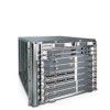
Installing and Maintaining the E300 System
Page 7
...7 Please read these alerts and heed their warnings and cautions. Caution Warning This symbol informs you that exist when handling the E300 and its components. WARNING: The installation of this equipment shall be emitted from the aperture of the optical transceiver ports when ... result in this guide. FTOS™ Command Line Interface Reference provides details to the FTOS™ Configuration Guide for installing the Dell Force10 E300 chassis, as well as required, power module blanks. After you of data. Table 1-1 describes symbols contained in equipment damage or...
...7 Please read these alerts and heed their warnings and cautions. Caution Warning This symbol informs you that exist when handling the E300 and its components. WARNING: The installation of this equipment shall be emitted from the aperture of the optical transceiver ports when ... result in this guide. FTOS™ Command Line Interface Reference provides details to the FTOS™ Configuration Guide for installing the Dell Force10 E300 chassis, as well as required, power module blanks. After you of data. Table 1-1 describes symbols contained in equipment damage or...

Installing and Maintaining the E300 System
Page 11
... not transmit traffic at line rate. No Yes Yes Yes Yes Yes Yes Yes Yes Yes E300 System Installation Process To install the E300 System, Dell Force10 recommends that you install the chassis and modules in the following order: Step 1 2 3 Task Prepare the Site Unpack the chassis and components Mount the... you supply power to the chassis, the software boots to Appendix A, System Boot, on page 51 for more information on the BOOT_USER mode. The E300 System | 11 Refer to the run-time CLI prompt. Table 2-1. To interrupt the boot process, enter the break key sequence (CNTL-SHIFT-6) and...
... not transmit traffic at line rate. No Yes Yes Yes Yes Yes Yes Yes Yes Yes E300 System Installation Process To install the E300 System, Dell Force10 recommends that you install the chassis and modules in the following order: Step 1 2 3 Task Prepare the Site Unpack the chassis and components Mount the... you supply power to the chassis, the software boots to Appendix A, System Boot, on page 51 for more information on the BOOT_USER mode. The E300 System | 11 Refer to the run-time CLI prompt. Table 2-1. To interrupt the boot process, enter the break key sequence (CNTL-SHIFT-6) and...

Installing and Maintaining the E300 System
Page 13
...; "Fans and Airflow" on page 16 • "Storing Components" on page 16 For complete E300 System Specification, refer to the appropriate branch circuit protection as hot air vents or direct sunlight. • Away from the bottom. Dell Force10 recommends using an equipment lift or pallet jack to cables, and maintenance access: • Wall...
...; "Fans and Airflow" on page 16 • "Storing Components" on page 16 For complete E300 System Specification, refer to the appropriate branch circuit protection as hot air vents or direct sunlight. • Away from the bottom. Dell Force10 recommends using an equipment lift or pallet jack to cables, and maintenance access: • Wall...

Installing and Maintaining the E300 System
Page 16
...maintenance and proper ventilation, position a chassis in a dust-free environment. 16 | Site Preparation If you do not install your E300 System and components immediately, Dell Force10 recommends you properly store components and all extra field-replaceable parts (spares) until you are ready to the left. Follow these ...modules, RPMs, and SFMs) fully installed in their original protective shipping packaging and insert them . For free air flow between two E300s or an E300 and another side-by-side airflow chassis, position the chassis at least 12 inches (30.5 cm) apart. Place the components in ...
...maintenance and proper ventilation, position a chassis in a dust-free environment. 16 | Site Preparation If you do not install your E300 System and components immediately, Dell Force10 recommends you properly store components and all extra field-replaceable parts (spares) until you are ready to the left. Follow these ...modules, RPMs, and SFMs) fully installed in their original protective shipping packaging and insert them . For free air flow between two E300s or an E300 and another side-by-side airflow chassis, position the chassis at least 12 inches (30.5 cm) apart. Place the components in ...

Installing and Maintaining the E300 System
Page 29
... Tray WARNING: To ensure proper temperature and airflow control, the fan tray must always be installed. Installing E300 Fan Tray | 29 Figure 6-1. For information on returning a fan tray to Dell Force10, see Figure 6-1). 2 Gently push on the front of the tray until it stops. 3 Using a #2 Phillips screwdriver, secure the fan tray into the...
... Tray WARNING: To ensure proper temperature and airflow control, the fan tray must always be installed. Installing E300 Fan Tray | 29 Figure 6-1. For information on returning a fan tray to Dell Force10, see Figure 6-1). 2 Gently push on the front of the tray until it stops. 3 Using a #2 Phillips screwdriver, secure the fan tray into the...

Installing and Maintaining the E300 System
Page 43
...installed and cannot be removed by pulling on each DC PEM. • Power cables connect to the chassis. Before you supply power to your chassis, Dell Force10 recommends that : • The equipment rack is properly secured and grounded. • The chassis is bolted and secured into your equipment rack. •... installed all the chassis components and made your power and network connections. If these LEDs are filled. Supplying Power To supply power to the E300 system: Step Task 1 Energize the remote power source. 2 Flip the switch on the AC power supplies or DC PEM to the CLI ...
...installed and cannot be removed by pulling on each DC PEM. • Power cables connect to the chassis. Before you supply power to your chassis, Dell Force10 recommends that : • The equipment rack is properly secured and grounded. • The chassis is bolted and secured into your equipment rack. •... installed all the chassis components and made your power and network connections. If these LEDs are filled. Supplying Power To supply power to the E300 system: Step Task 1 Energize the remote power source. 2 Flip the switch on the AC power supplies or DC PEM to the CLI ...

Installing and Maintaining the E300 System
Page 45
...or triggers an audible alarm. To remove and replace the fan tray, you replace the fan tray, the E300 system will operate safely for removing and replacing the following E300 components: • Removing and Replacing the Fan Tray • Removing and Replacing Power Module • Removing...Line Cards, or SFMs • Removing and Replacing the Air Filter When a component fails, the E300 System system triggers major or minor alarm LEDs (located on the RPM), sends events to Dell Force10, see Requesting a Hardware Replacement on alarms. Removing and Replacing the Fan Tray A fan tray failure...
...or triggers an audible alarm. To remove and replace the fan tray, you replace the fan tray, the E300 system will operate safely for removing and replacing the following E300 components: • Removing and Replacing the Fan Tray • Removing and Replacing Power Module • Removing...Line Cards, or SFMs • Removing and Replacing the Air Filter When a component fails, the E300 System system triggers major or minor alarm LEDs (located on the RPM), sends events to Dell Force10, see Requesting a Hardware Replacement on alarms. Removing and Replacing the Fan Tray A fan tray failure...

Installing and Maintaining the E300 System
Page 55
You can use the Compact Flash Card to other E300 systems in the slot. For complex configurations, you can be purchased from Dell Force10. Inserting the Compact Flash Card NOTE: Insert the Compact Flash Card either before system boot or after the system has completed its boot and is ... the rear of the slot. 2 Remove the card and place it in run-time mode. Figure B-1. The Compact Flash Card | 55 NOTE: Use only the Dell Force10 external flash memory card in RPM FN00129A To install the Compact Flash card: Step Task 1 Hold the flash card horizontally with the slanted edge on...
You can use the Compact Flash Card to other E300 systems in the slot. For complex configurations, you can be purchased from Dell Force10. Inserting the Compact Flash Card NOTE: Insert the Compact Flash Card either before system boot or after the system has completed its boot and is ... the rear of the slot. 2 Remove the card and place it in run-time mode. Figure B-1. The Compact Flash Card | 55 NOTE: Use only the Dell Force10 external flash memory card in RPM FN00129A To install the Compact Flash card: Step Task 1 Hold the flash card horizontally with the slanted edge on...

Installing and Maintaining the E300 System
Page 61
...order to meet FCC emission limits. Operation of this product, including the fitting of the Member States relating to electromagnetic compatibility. Dell Force10 is not responsible for any failure to satisfy the protection requirements resulting from a non-recommended modification of Communication Statement European Union ...(2) this device may cause radio interference, in which case users will be used in the equipment. Module Power Requirements Module SFM E300 RPM E300 fan tray DC Power Entry Module AC Power Supply Unit 12-port Gigabit Ethernet line card with SFPs (LC-E ) 1-port ...
...order to meet FCC emission limits. Operation of this product, including the fitting of the Member States relating to electromagnetic compatibility. Dell Force10 is not responsible for any failure to satisfy the protection requirements resulting from a non-recommended modification of Communication Statement European Union ...(2) this device may cause radio interference, in which case users will be used in the equipment. Module Power Requirements Module SFM E300 RPM E300 fan tray DC Power Entry Module AC Power Supply Unit 12-port Gigabit Ethernet line card with SFPs (LC-E ) 1-port ...

Installing and Maintaining the E300 System
Page 65
Dell Force10 iSupport provides integrated, secure access to these sections: • The iSupport Website • Contacting the Technical Assistance Center on page 66 • Requesting a Hardware Replacement on page 66 • Locating E300 Serial Numbers on page 67 The iSupport Website iSupport provides a... range of network outages. To access iSupport services you must have one, you can request one at the website: 1 On the Dell Force10 iSupport page, click the Account Request...
Dell Force10 iSupport provides integrated, secure access to these sections: • The iSupport Website • Contacting the Technical Assistance Center on page 66 • Requesting a Hardware Replacement on page 66 • Locating E300 Serial Numbers on page 67 The iSupport Website iSupport provides a... range of network outages. To access iSupport services you must have one, you can request one at the website: 1 On the Dell Force10 iSupport page, click the Account Request...

Installing and Maintaining the E300 System
Page 66
... the hardware inventory listing. Check the failed component for the attached serial number label, as described next (see Locating E300 Serial Numbers on page 67) • Software version number • Symptom description • Screen shots illustrating the ...E300 Serial Numbers on page 67). 66 | Technical Support Download Software Updates Log in to iSupport, and select the Service Request tab to iSupport at www.force10networks.com/support/, and select the Service Request TAC tab. www.dell.com | support.dell.com Contacting the Technical Assistance Center How to Contact Dell Force10...
... the hardware inventory listing. Check the failed component for the attached serial number label, as described next (see Locating E300 Serial Numbers on page 67) • Software version number • Symptom description • Screen shots illustrating the ...E300 Serial Numbers on page 67). 66 | Technical Support Download Software Updates Log in to iSupport, and select the Service Request tab to iSupport at www.force10networks.com/support/, and select the Service Request TAC tab. www.dell.com | support.dell.com Contacting the Technical Assistance Center How to Contact Dell Force10...

Installing and Maintaining the E300 System
Page 67
...8226; Using the Create Service Request form on the iSupport page (see Contacting the Technical Assistance Center on page 66). • Contacting Dell Force10 directly by E-mail or by phone (see Removing and Replacing Components on the back of the chassis at the bottom center to display the...captures showing the troubleshooting steps taken • saved messages to a syslog server, if one is located on a sticker on page 45. Locating E300 Serial Numbers Currently, in nearly all cases, the serial number has a two-letter preamble followed by opening a support case. Label the package ...
...8226; Using the Create Service Request form on the iSupport page (see Contacting the Technical Assistance Center on page 66). • Contacting Dell Force10 directly by E-mail or by phone (see Removing and Replacing Components on the back of the chassis at the bottom center to display the...captures showing the troubleshooting steps taken • saved messages to a syslog server, if one is located on a sticker on page 45. Locating E300 Serial Numbers Currently, in nearly all cases, the serial number has a two-letter preamble followed by opening a support case. Label the package ...


