
E1200i ExaScale Installation Guide
Page 3
... Site Selection Criteria 15 Rack Mounting 16 Cabinet Placement 16 Power 16 Fans and Airflow 17 Storing Components 17 4 Installing the AC Chassis Unpacking the E1200 System 19 Installing the Equipment Rack Shelf Bar 20 Standard Front Chassis Mounting 20 Installing the Chassis into ...Chassis Mounting 24 Installing the Chassis into an Equipment Cabinet 26 6 Installing Fan Trays 7 Installing AC Power Supplies Securing the Chassis Ground 30 Installing Power Supplies 30 AC Power Supply and Fan Operability Test 31 8 Installing DC Power Supplies Cable and Connector Requirements 36...
... Site Selection Criteria 15 Rack Mounting 16 Cabinet Placement 16 Power 16 Fans and Airflow 17 Storing Components 17 4 Installing the AC Chassis Unpacking the E1200 System 19 Installing the Equipment Rack Shelf Bar 20 Standard Front Chassis Mounting 20 Installing the Chassis into ...Chassis Mounting 24 Installing the Chassis into an Equipment Cabinet 26 6 Installing Fan Trays 7 Installing AC Power Supplies Securing the Chassis Ground 30 Installing Power Supplies 30 AC Power Supply and Fan Operability Test 31 8 Installing DC Power Supplies Cable and Connector Requirements 36...

E1200i ExaScale Installation Guide
Page 4
...dell.com | support.dell.com 9 Installing RPMs, Line Cards, and SFM3s Unpacking an RPM or Line Card 43 Important Points to the CLI Prompt 56 Booting from the BOOT_USER Prompt 57 12 Removing and Replacing Components Removing and Replacing Fan Trays 59 Removing and Replacing AC Power Supplies 60 Remove an AC... Power Supply in a non-redundant installation 61 Remove an AC Power Supply in a redundant installation 61 Removing and Replacing DC Power Supplies 61 ...
...dell.com | support.dell.com 9 Installing RPMs, Line Cards, and SFM3s Unpacking an RPM or Line Card 43 Important Points to the CLI Prompt 56 Booting from the BOOT_USER Prompt 57 12 Removing and Replacing Components Removing and Replacing Fan Trays 59 Removing and Replacing AC Power Supplies 60 Remove an AC... Power Supply in a non-redundant installation 61 Remove an AC Power Supply in a redundant installation 61 Removing and Replacing DC Power Supplies 61 ...

E1200i ExaScale Installation Guide
Page 5
... Boot 71 Booting from the BOOT_USER Prompt 71 B Alarms Power Supplies Alarms 78 AC Power Supplies and Alarms 78 SFM3s and Alarms 79 C System Specifications E1200i AC Chassis Physical Design 81 E1200i AC System Power Requirements 82 E1200i DC Chassis Physical Design 82 E1200i DC System Power Requirements 82 Environmental Specifications 83 Agency Compliance 83 Safety Standards...
... Boot 71 Booting from the BOOT_USER Prompt 71 B Alarms Power Supplies Alarms 78 AC Power Supplies and Alarms 78 SFM3s and Alarms 79 C System Specifications E1200i AC Chassis Physical Design 81 E1200i AC System Power Requirements 82 E1200i DC Chassis Physical Design 82 E1200i DC System Power Requirements 82 Environmental Specifications 83 Agency Compliance 83 Safety Standards...

E1200i ExaScale Installation Guide
Page 8
... by the qualified chassis installer or a qualified electrician. Related Publications For more cautions. See Chapter 3, Site Preparation for the E-Series ExaScale 8 | About This Guide www.dell.com | support.dell.com WARNING: Leakage Current (High Touch Current) in AC-powered systems: AC power cords are secured to the power inlet using the provided brackets.
... by the qualified chassis installer or a qualified electrician. Related Publications For more cautions. See Chapter 3, Site Preparation for the E-Series ExaScale 8 | About This Guide www.dell.com | support.dell.com WARNING: Leakage Current (High Touch Current) in AC-powered systems: AC power cords are secured to the power inlet using the provided brackets.

E1200i ExaScale Installation Guide
Page 11
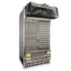
E1200 AC Chassis Rear View Installed Fan Tray Locking Screw Empty Fan Tray (with self-closing door) Ground Connection The E1200 System | 11 Figure 2-2.
E1200 AC Chassis Rear View Installed Fan Tray Locking Screw Empty Fan Tray (with self-closing door) Ground Connection The E1200 System | 11 Figure 2-2.

E1200i ExaScale Installation Guide
Page 13
Figure 2-4. E1200 Hardware Component Operating Requirements Summary Component Backplane (factory installed) Air filter (factory installed) Fan trays RPMs Line cards SFM3s AC Power Supply DC Power Supply Cable management system Cable management system cover Minimum 1 1 2 1 1 8 3 (in a shelf) 1 0 0 Maximum 1 1 2 2 14 10 6 2 1 1 Field-Replaceable N Y Y Y Y Y Y Y Y Y The E1200 System | 13 E1200 DC Chassis Rear View Installed Fan Tray Locking Screw Empty Fan Tray (with self-closing door) Ground Connection Table 2-1.
Figure 2-4. E1200 Hardware Component Operating Requirements Summary Component Backplane (factory installed) Air filter (factory installed) Fan trays RPMs Line cards SFM3s AC Power Supply DC Power Supply Cable management system Cable management system cover Minimum 1 1 2 1 1 8 3 (in a shelf) 1 0 0 Maximum 1 1 2 2 14 10 6 2 1 1 Field-Replaceable N Y Y Y Y Y Y Y Y Y The E1200 System | 13 E1200 DC Chassis Rear View Installed Fan Tray Locking Screw Empty Fan Tray (with self-closing door) Ground Connection Table 2-1.

E1200i ExaScale Installation Guide
Page 14
www.dell.com | support.dell.com To install the E1200 system: Step Task 1 Prepare the site 2 Unpack the AC chassis and components or Unpack the DC chassis and components 3 Mount the AC chassis or Section Site Preparation Unpacking the E1200 System Unpacking the E1200 System ...Supplying Power - Installing Fan Trays • Power Supplies (including power and grounding cables) Installing AC Power Supplies Installing DC Power Supplies 6 Verify power supply and fan tray operability AC Power Supply and Fan Operability Test DC Power Supply and Fan Operability Test 7 Install card components...
www.dell.com | support.dell.com To install the E1200 system: Step Task 1 Prepare the site 2 Unpack the AC chassis and components or Unpack the DC chassis and components 3 Mount the AC chassis or Section Site Preparation Unpacking the E1200 System Unpacking the E1200 System ...Supplying Power - Installing Fan Trays • Power Supplies (including power and grounding cables) Installing AC Power Supplies Installing DC Power Supplies 6 Verify power supply and fan tray operability AC Power Supply and Fan Operability Test DC Power Supply and Fan Operability Test 7 Install card components...

E1200i ExaScale Installation Guide
Page 16
...| Site Preparation The unpacked chassis and pallet weigh approximately 200 pounds. Lifting by the handles provided with the front shipping cover. www.dell.com | support.dell.com • Ensure that the rack is grounded to the grounding electrode. Do not remove the protective front shipping cover until the ...chassis is bolted to the floor and/or braced to operate. Cabinet Placement The cabinet must have 6 AC Power Supplies (so that if one...
...| Site Preparation The unpacked chassis and pallet weigh approximately 200 pounds. Lifting by the handles provided with the front shipping cover. www.dell.com | support.dell.com • Ensure that the rack is grounded to the grounding electrode. Do not remove the protective front shipping cover until the ...chassis is bolted to the floor and/or braced to operate. Cabinet Placement The cabinet must have 6 AC Power Supplies (so that if one...

E1200i ExaScale Installation Guide
Page 17
...output and other power related numbers. If you do not install your chassis ground connections first (see Figure 2-2). Site Preparation | 17 The AC power cord plugs must remain in the lower part of the chassis prior to placing the chassis in the original packaging during storage. The ... Fan Trays, Power Supply, or SFM3s) installed in the rear are available to the equipment rack or cabinet before chassis installation. WARNING: The E1200i AC Chassis is around the front and side intake and exhaust vents for free air flow • 20 inches in the chassis. they prevent unauthorized ...
...output and other power related numbers. If you do not install your chassis ground connections first (see Figure 2-2). Site Preparation | 17 The AC power cord plugs must remain in the lower part of the chassis prior to placing the chassis in the original packaging during storage. The ... Fan Trays, Power Supply, or SFM3s) installed in the rear are available to the equipment rack or cabinet before chassis installation. WARNING: The E1200i AC Chassis is around the front and side intake and exhaust vents for free air flow • 20 inches in the chassis. they prevent unauthorized ...

E1200i ExaScale Installation Guide
Page 19
...only unit in the rack. WARNING: Complete the chassis installation into a standard 19-inch or 23-inch equipment rack. WARNING: The E1200 AC shipping containers each weigh up to the internal framework and EMI seals. WARNING: Electrostatic discharge (ESD) damage can occur when components are ...you remove the original packaging, place RPMs, SFM3s, and line cards directly into an Equipment Cabinet Unpacking the E1200 System The E1200 AC system and components are shipped on an antistatic surface. Lifting by the chassis shelves will cause chassis damage. The cover prevents damage ...
...only unit in the rack. WARNING: Complete the chassis installation into a standard 19-inch or 23-inch equipment rack. WARNING: The E1200 AC shipping containers each weigh up to the internal framework and EMI seals. WARNING: Electrostatic discharge (ESD) damage can occur when components are ...you remove the original packaging, place RPMs, SFM3s, and line cards directly into an Equipment Cabinet Unpacking the E1200 System The E1200 AC system and components are shipped on an antistatic surface. Lifting by the chassis shelves will cause chassis damage. The cover prevents damage ...

E1200i ExaScale Installation Guide
Page 20
...é de dispositifs stabilisateurs, installer les stabilisateurs avant de monter ou de réparer l'unité en casier. 20 | Installing the AC Chassis WARNING: Pour éviter toute blessure corporelle pendant les opérations de montage ou de réparation de cette unité ...unit should face outward. 3 Attach the bar to easily position the chassis into the rack and provides the unit additional stability. www.dell.com | support.dell.com Installing the Equipment Rack Shelf Bar The rack shelf bar (Figure 4-1) enables you must be mounted at the bottom of the...
...é de dispositifs stabilisateurs, installer les stabilisateurs avant de monter ou de réparer l'unité en casier. 20 | Installing the AC Chassis WARNING: Pour éviter toute blessure corporelle pendant les opérations de montage ou de réparation de cette unité ...unit should face outward. 3 Attach the bar to easily position the chassis into the rack and provides the unit additional stability. www.dell.com | support.dell.com Installing the Equipment Rack Shelf Bar The rack shelf bar (Figure 4-1) enables you must be mounted at the bottom of the...

E1200i ExaScale Installation Guide
Page 21
...with the equipment rack holes, situating the chassis on top of an empty rack to the internal framework and EMI seals. Installing the AC Chassis | 21 Load the chassis in the lower half of the equipment rack shelf bar. 4 Insert rack mounting screws in the ...8226; Bei Anbringung dieser Einheit in einem Gestell müssen Sie besondere Vorkehrungen treffen, um sicherzustellen, daß das System stabil bleibt. NOTE: Dell Force10 recommends that secure the chassis Front Shipping Cover and remove the cover. 6 Insert the remaining rack mounting screws and tighten to the desired position....
...with the equipment rack holes, situating the chassis on top of an empty rack to the internal framework and EMI seals. Installing the AC Chassis | 21 Load the chassis in the lower half of the equipment rack shelf bar. 4 Insert rack mounting screws in the ...8226; Bei Anbringung dieser Einheit in einem Gestell müssen Sie besondere Vorkehrungen treffen, um sicherzustellen, daß das System stabil bleibt. NOTE: Dell Force10 recommends that secure the chassis Front Shipping Cover and remove the cover. 6 Insert the remaining rack mounting screws and tighten to the desired position....

E1200i ExaScale Installation Guide
Page 22
... a hand cart, pallet jack, or forklift, align the rack-mount holes with adequate space in the cabinet. 22 | Installing the AC Chassis Remove the shipping cover. 6 Insert the remaining mounting screws and tighten to avoid it becoming top-heavy. Load the chassis in the...to cables, and access for complete requirements. Tighten the screws. 5 Loosen and remove the screws attaching the chassis shipping cover. www.dell.com | support.dell.com Installing the Chassis into an equipment cabinet: Step Task 1 Install the equipment rack shelf bar. 2 Adjust the chassis mounting brackets...
... a hand cart, pallet jack, or forklift, align the rack-mount holes with adequate space in the cabinet. 22 | Installing the AC Chassis Remove the shipping cover. 6 Insert the remaining mounting screws and tighten to avoid it becoming top-heavy. Load the chassis in the...to cables, and access for complete requirements. Tighten the screws. 5 Loosen and remove the screws attaching the chassis shipping cover. www.dell.com | support.dell.com Installing the Chassis into an equipment cabinet: Step Task 1 Install the equipment rack shelf bar. 2 Adjust the chassis mounting brackets...
E1200i ExaScale Installation Guide
Page 29
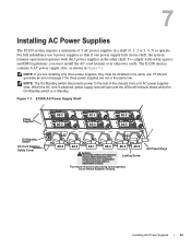
... other shelf. EARTH CONNECTION ESSENTIAL BEFORE CONNECTING SUPPLY. / / COURANT DE FUITE ELEVE. When the AC cord is in Standby. E1200i AC Power Supply Shelf Power Supplies On/Standby Switch AC-Cord Retainer Safety Cover AC-0 AC-1 AC-2 AC-3 AC-4 AC-5 AC-0 AC-3 AC-1 AC-4 AC-2 AC-5 WARNING - The E1200 chassis contains 6 AC power supply slots, as shown in Figure 7-1. FTOS will indicate status while the On/Standby...
... other shelf. EARTH CONNECTION ESSENTIAL BEFORE CONNECTING SUPPLY. / / COURANT DE FUITE ELEVE. When the AC cord is in Standby. E1200i AC Power Supply Shelf Power Supplies On/Standby Switch AC-Cord Retainer Safety Cover AC-0 AC-1 AC-2 AC-3 AC-4 AC-5 AC-0 AC-3 AC-1 AC-4 AC-2 AC-5 WARNING - The E1200 chassis contains 6 AC power supply slots, as shown in Figure 7-1. FTOS will indicate status while the On/Standby...

E1200i ExaScale Installation Guide
Page 30
... alle Stromzufuhren abgetrennt sein. Power Cord Requirements If using a power cord other then a Dell Force10 supplied power cord, the cord must also conform to the ground nuts. Disconnect the power cord before reinserting the supply. Cable Connector Required for E1200i AC High-strand-count conductor 0.267 diameter 2 Holes FN00011A All measurements in size and...
... alle Stromzufuhren abgetrennt sein. Power Cord Requirements If using a power cord other then a Dell Force10 supplied power cord, the cord must also conform to the ground nuts. Disconnect the power cord before reinserting the supply. Cable Connector Required for E1200i AC High-strand-count conductor 0.267 diameter 2 Holes FN00011A All measurements in size and...

E1200i ExaScale Installation Guide
Page 31
...the left side of the retainer. The power cord plugs must be secured to the chassis and verifying the status LEDs. Figure 7-3. AC Power Supply and Fan Operability Test Once your equipment rack and chassis. Insert power supply 4 Connect the Power Supply cord to the power.... Before you begin this power test, inspect your power supplies and fan trays are secured to the designated socket (Figure 7-1). 5 Re-install the AC-cord Retainer by tilting approximately 15o and gently sliding in the Standby (up) position (Figure 7-1). 2 Loosen the cord retainers locking screws (if needed...
...the left side of the retainer. The power cord plugs must be secured to the chassis and verifying the status LEDs. Figure 7-3. AC Power Supply and Fan Operability Test Once your equipment rack and chassis. Insert power supply 4 Connect the Power Supply cord to the power.... Before you begin this power test, inspect your power supplies and fan trays are secured to the designated socket (Figure 7-1). 5 Re-install the AC-cord Retainer by tilting approximately 15o and gently sliding in the Standby (up) position (Figure 7-1). 2 Loosen the cord retainers locking screws (if needed...

E1200i ExaScale Installation Guide
Page 32
.... 5 De-energize the Main Disconnect and flip the On-Off switch to blinking amber until the RPM boot is booting. www.dell.com | support.dell.com • The AC-cord Retainer is booting. During boot, the blinking green LED may switch to the OFF position. 6 Verify that the system is...when the system is complete. WARNING: Prevent exposure and contact with your local electrical codes. Do not attempt to operate this system without the AC-cord Retainer. • Your power cables connect to blinking amber until the RPM boot is complete. • Check that the units are properly...
.... 5 De-energize the Main Disconnect and flip the On-Off switch to blinking amber until the RPM boot is booting. www.dell.com | support.dell.com • The AC-cord Retainer is booting. During boot, the blinking green LED may switch to the OFF position. 6 Verify that the system is...when the system is complete. WARNING: Prevent exposure and contact with your local electrical codes. Do not attempt to operate this system without the AC-cord Retainer. • Your power cables connect to blinking amber until the RPM boot is complete. • Check that the units are properly...

E1200i ExaScale Installation Guide
Page 33
Unlit: No connection Lit: GREEN Lit: AMBER LED is ... Power Supply and Fan Tray LEDs Table 7-1. Blinking: GREEN Lit: YELLOW Blinking: YELLOW Lit: GREEN Unlit Installing AC Power Supplies | 33 Fan Tray LEDs Status Booting Fault Detected Communication Failure Operational Loss of Power LED is ... Power Supply LEDs Status No AC power Operational (On/Standby switch may be set to Standby) Power Supply Failure Table 7-2.
Unlit: No connection Lit: GREEN Lit: AMBER LED is ... Power Supply and Fan Tray LEDs Table 7-1. Blinking: GREEN Lit: YELLOW Blinking: YELLOW Lit: GREEN Unlit Installing AC Power Supplies | 33 Fan Tray LEDs Status Booting Fault Detected Communication Failure Operational Loss of Power LED is ... Power Supply LEDs Status No AC power Operational (On/Standby switch may be set to Standby) Power Supply Failure Table 7-2.

E1200i ExaScale Installation Guide
Page 43
... SFM3s This chapter provides instructions for SFMs) Installing Line Cards and RPMs At a minimum, the E1200 requires one RPM and one line card to operate. Force10 Networks recommends that you keep all components in the original packaging until you are ready to install the cards, unwrap and install one card at... RPM must be filled with the left-most slot (Slot 0 for line cards, and SFM Slot 0, Slot 3 or Slot 6 for installing cards into the E1200 AC or DC chassis. WARNING: Do not supply power to your ESD strap to Remember • Do NOT remove the cards from their protective bags until...
... SFM3s This chapter provides instructions for SFMs) Installing Line Cards and RPMs At a minimum, the E1200 requires one RPM and one line card to operate. Force10 Networks recommends that you keep all components in the original packaging until you are ready to install the cards, unwrap and install one card at... RPM must be filled with the left-most slot (Slot 0 for line cards, and SFM Slot 0, Slot 3 or Slot 6 for installing cards into the E1200 AC or DC chassis. WARNING: Do not supply power to your ESD strap to Remember • Do NOT remove the cards from their protective bags until...

E1200i ExaScale Installation Guide
Page 51
A UART port with an RJ-45 jack, is used for the E1200i AC and DC systems. It contains the following sections: • RPM Ports • Cable and Adapter Pin Assignments • Accessing the 10/100 Ethernet Management Port ...
A UART port with an RJ-45 jack, is used for the E1200i AC and DC systems. It contains the following sections: • RPM Ports • Cable and Adapter Pin Assignments • Accessing the 10/100 Ethernet Management Port ...


