
E1200i ExaScale Installation Guide
Page 3
...Publications 8 2 The E1200 System Operating Overview 9 3 Site Preparation Site Selection Criteria 15 Rack Mounting 16 Cabinet Placement 16 Power 16 Fans and Airflow 17 Storing Components 17 4 Installing the AC Chassis Unpacking the E1200 System 19 Installing the Equipment ... 26 6 Installing Fan Trays 7 Installing AC Power Supplies Securing the Chassis Ground 30 Installing Power Supplies 30 AC Power Supply and Fan Operability Test 31 8 Installing DC Power Supplies Cable and Connector Requirements 36 Installing DC PEMs 36 DC Power Supply and Fan Operability Test 40 Contents | 3
...Publications 8 2 The E1200 System Operating Overview 9 3 Site Preparation Site Selection Criteria 15 Rack Mounting 16 Cabinet Placement 16 Power 16 Fans and Airflow 17 Storing Components 17 4 Installing the AC Chassis Unpacking the E1200 System 19 Installing the Equipment ... 26 6 Installing Fan Trays 7 Installing AC Power Supplies Securing the Chassis Ground 30 Installing Power Supplies 30 AC Power Supply and Fan Operability Test 31 8 Installing DC Power Supplies Cable and Connector Requirements 36 Installing DC PEMs 36 DC Power Supply and Fan Operability Test 40 Contents | 3

E1200i ExaScale Installation Guide
Page 4
... 53 Accessing the Auxiliary Port by Modem 54 Accessing the 10/100 Ethernet Management Port 54 Universal Serial Bus Ports 54 11 Powering Up Preparation 55 Supplying Power - www.dell.com | support.dell.com 9 Installing RPMs, Line Cards, and SFM3s Unpacking an RPM or Line Card 43 Important Points to the CLI Prompt 56 Booting...
... 53 Accessing the Auxiliary Port by Modem 54 Accessing the 10/100 Ethernet Management Port 54 Universal Serial Bus Ports 54 11 Powering Up Preparation 55 Supplying Power - www.dell.com | support.dell.com 9 Installing RPMs, Line Cards, and SFM3s Unpacking an RPM or Line Card 43 Important Points to the CLI Prompt 56 Booting...

E1200i ExaScale Installation Guide
Page 5
... 71 System Boot 71 Booting from the BOOT_USER Prompt 71 B Alarms Power Supplies Alarms 78 AC Power Supplies and Alarms 78 SFM3s and Alarms 79 C System Specifications E1200i AC Chassis Physical Design 81 E1200i AC System Power Requirements 82 E1200i DC Chassis Physical Design 82 E1200i DC System Power Requirements 82 Environmental Specifications 83 Agency Compliance 83 Safety Standards and...
... 71 System Boot 71 Booting from the BOOT_USER Prompt 71 B Alarms Power Supplies Alarms 78 AC Power Supplies and Alarms 78 SFM3s and Alarms 79 C System Specifications E1200i AC Chassis Physical Design 81 E1200i AC System Power Requirements 82 E1200i DC Chassis Physical Design 82 E1200i DC System Power Requirements 82 Environmental Specifications 83 Agency Compliance 83 Safety Standards and...

E1200i ExaScale Installation Guide
Page 7
... instructions to avoid ESD damage. The E1200 system is connected. E1200i systems run Dell Force10 OS (FTOS™) software. Information Symbols Symbol Warning Note Description This symbol informs you complete the hardware installation process and power up this equipment to install its fan trays, power supplies, route processor modules (RPMs), switch fabric modules (SFM3s), and line...
... instructions to avoid ESD damage. The E1200 system is connected. E1200i systems run Dell Force10 OS (FTOS™) software. Information Symbols Symbol Warning Note Description This symbol informs you complete the hardware installation process and power up this equipment to install its fan trays, power supplies, route processor modules (RPMs), switch fabric modules (SFM3s), and line...

E1200i ExaScale Installation Guide
Page 13
E1200 Hardware Component Operating Requirements Summary Component Backplane (factory installed) Air filter (factory installed) Fan trays RPMs Line cards SFM3s AC Power Supply DC Power Supply Cable management system Cable management system cover Minimum 1 1 2 1 1 8 3 (in a shelf) 1 0 0 Maximum 1 1 2 2 14 10 6 2 1 1 Field-Replaceable N Y Y Y Y Y Y Y Y Y The E1200 System | 13 Figure 2-4. E1200 DC Chassis Rear View Installed Fan Tray Locking Screw Empty Fan Tray (with self-closing door) Ground Connection Table 2-1.
E1200 Hardware Component Operating Requirements Summary Component Backplane (factory installed) Air filter (factory installed) Fan trays RPMs Line cards SFM3s AC Power Supply DC Power Supply Cable management system Cable management system cover Minimum 1 1 2 1 1 8 3 (in a shelf) 1 0 0 Maximum 1 1 2 2 14 10 6 2 1 1 Field-Replaceable N Y Y Y Y Y Y Y Y Y The E1200 System | 13 Figure 2-4. E1200 DC Chassis Rear View Installed Fan Tray Locking Screw Empty Fan Tray (with self-closing door) Ground Connection Table 2-1.

E1200i ExaScale Installation Guide
Page 14
...to the runtime CLI. Installing Fan Trays • Power Supplies (including power and grounding cables) Installing AC Power Supplies Installing DC Power Supplies 6 Verify power supply and fan tray operability AC Power Supply and Fan Operability Test DC Power Supply and Fan Operability Test 7 Install card components: &#... Cables 9 Supply power to the chassis Supplying Power - To interrupt the automatic boot process, issue a break key sequence (Ctrl^) if you experience boot problems. The console monitor will display the default BOOT_USER # prompt. www.dell.com | support.dell.com To ...
...to the runtime CLI. Installing Fan Trays • Power Supplies (including power and grounding cables) Installing AC Power Supplies Installing DC Power Supplies 6 Verify power supply and fan tray operability AC Power Supply and Fan Operability Test DC Power Supply and Fan Operability Test 7 Install card components: &#... Cables 9 Supply power to the chassis Supplying Power - To interrupt the automatic boot process, issue a break key sequence (Ctrl^) if you experience boot problems. The console monitor will display the default BOOT_USER # prompt. www.dell.com | support.dell.com To ...

E1200i ExaScale Installation Guide
Page 16
... (0, 1, 2 or 3, 4, 5) or 1 DC PEM to ensure rack stability. The equipment rack must have 6 AC Power Supplies (so that if one power supply fails in one type of power module, either from the bottom or by the chassis shelves or fan tray openings will need a clearance of at least 20... one shelf, the system remains operational operates with the 3 power supplies in the other shelf) or a second 2 DC Power Entry Module (2 total) CAUTION: You cannot power the system with both types of the rack to operate. www.dell.com | support.dell.com • Ensure that the equipment is properly grounded....
... (0, 1, 2 or 3, 4, 5) or 1 DC PEM to ensure rack stability. The equipment rack must have 6 AC Power Supplies (so that if one power supply fails in one type of power module, either from the bottom or by the chassis shelves or fan tray openings will need a clearance of at least 20... one shelf, the system remains operational operates with the 3 power supplies in the other shelf) or a second 2 DC Power Entry Module (2 total) CAUTION: You cannot power the system with both types of the rack to operate. www.dell.com | support.dell.com • Ensure that the equipment is properly grounded....

E1200i ExaScale Installation Guide
Page 17
...modules in the rear are ready to access the fan tray • the system can operate with components (line cards, power supplies, RPMs, Fan Trays, Power Supply, or SFM3s) installed in the original packaging during storage. WARNING: Never operate the E1200 system with blank panels. Two ...DC units are required for specifications on replacing a fan tray, refer to the equipment rack or cabinet before chassis installation. WARNING: The E1200i AC ...
...modules in the rear are ready to access the fan tray • the system can operate with components (line cards, power supplies, RPMs, Fan Trays, Power Supply, or SFM3s) installed in the original packaging during storage. WARNING: Never operate the E1200 system with blank panels. Two ...DC units are required for specifications on replacing a fan tray, refer to the equipment rack or cabinet before chassis installation. WARNING: The E1200i AC ...

E1200i ExaScale Installation Guide
Page 19
...the top with the heaviest component at the bottom of the rack if it is the only unit in the rack. Do not unpack the power supplies, fan trays, air filter, or cards until the chassis is provided with a hand cart, pallet jack, or fork lift to the internal...containers each weigh up to lift or move the chassis with stabilizing devices, install the stabilizers before you install any other component (fan trays, power supplies, line cards, RPMs, SFM3s, cables). Do not remove the shipping cover during the installation process. To prevent bodily injury when mounting or servicing...
...the top with the heaviest component at the bottom of the rack if it is the only unit in the rack. Do not unpack the power supplies, fan trays, air filter, or cards until the chassis is provided with a hand cart, pallet jack, or fork lift to the internal...containers each weigh up to lift or move the chassis with stabilizing devices, install the stabilizers before you install any other component (fan trays, power supplies, line cards, RPMs, SFM3s, cables). Do not remove the shipping cover during the installation process. To prevent bodily injury when mounting or servicing...

E1200i ExaScale Installation Guide
Page 23
...) damage can occur when components are shipped on a wooden pallet with Front Shipping cover. After you install any other component (fan trays, power supplies, line cards, RPMs, SFM3s, cables). bzw. Überstromschutz installiert ist. Remove the chassis from the bottom. The unpacked chassis and pallet...un disjoncteur de 150A? Stellen Sie sicher, daß eine Sicherung oder ein Unterbrecher von nicht mehr 150A? Do not unpack the power supplies, fan trays, air filter, or cards until the chassis is used on the building's installation for short-circuit (overcurrent) protection. ...
...) damage can occur when components are shipped on a wooden pallet with Front Shipping cover. After you install any other component (fan trays, power supplies, line cards, RPMs, SFM3s, cables). bzw. Überstromschutz installiert ist. Remove the chassis from the bottom. The unpacked chassis and pallet...un disjoncteur de 150A? Stellen Sie sicher, daß eine Sicherung oder ein Unterbrecher von nicht mehr 150A? Do not unpack the power supplies, fan trays, air filter, or cards until the chassis is used on the building's installation for short-circuit (overcurrent) protection. ...
E1200i ExaScale Installation Guide
Page 29
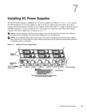
The E1200 chassis contains 6 AC power supply slots, as shown in Standby. E1200i AC Power Supply Shelf Power Supplies On/Standby Switch AC-Cord Retainer Safety Cover AC-0 AC-1 AC-2 AC-3 AC-4 AC-5 AC-0 AC-3 AC-1 AC-4 AC-2 AC-5 WARNING - NOTE: The On/Standby switch disconnects power to operate. When the AC cord is attached, power supply fans will spin and...
The E1200 chassis contains 6 AC power supply slots, as shown in Standby. E1200i AC Power Supply Shelf Power Supplies On/Standby Switch AC-Cord Retainer Safety Cover AC-0 AC-1 AC-2 AC-3 AC-4 AC-5 AC-0 AC-3 AC-1 AC-4 AC-2 AC-5 WARNING - NOTE: The On/Standby switch disconnects power to operate. When the AC cord is attached, power supply fans will spin and...

E1200i ExaScale Installation Guide
Page 30
...ß; Figure 7-2. The power source end of the power cord must comply with your Dell Force10 representative to your local electrical codes. The following are Dell Force10 supplied plug types. WARNING: This unit has more than one power supply connection; All power plugs must have stopped rotating...Cable Connector Required for your local electrical codes in inches. 0.750" Installing Power Supplies CAUTION: An E1200i AC power supply still has power after extraction, and has completely powered off when the fans have an appropriately sized plug that the socket-outlet...
...ß; Figure 7-2. The power source end of the power cord must comply with your Dell Force10 representative to your local electrical codes. The following are Dell Force10 supplied plug types. WARNING: This unit has more than one power supply connection; All power plugs must have stopped rotating...Cable Connector Required for your local electrical codes in inches. 0.750" Installing Power Supplies CAUTION: An E1200i AC power supply still has power after extraction, and has completely powered off when the fans have an appropriately sized plug that the socket-outlet...

E1200i ExaScale Installation Guide
Page 31
...in the long edge just above the AC cords. 6 Secure the retainer by the qualified chassis installer or a qualified electrician. Installing AC Power Supplies | 31 WARNING: Leakage Current (High Touch Current) in the Standby (up) position (Figure 7-1). 2 Loosen the cord retainers locking ... the cover away from the chassis. 3 Slide the power supplies into the assigned slot. Insert power supply 4 Connect the Power Supply cord to the chassis and verifying the status LEDs. The power cord plugs must be secured to the power inlet using the provided brackets. Step Task 1 Make ...
...in the long edge just above the AC cords. 6 Secure the retainer by the qualified chassis installer or a qualified electrician. Installing AC Power Supplies | 31 WARNING: Leakage Current (High Touch Current) in the Standby (up) position (Figure 7-1). 2 Loosen the cord retainers locking ... the cover away from the chassis. 3 Slide the power supplies into the assigned slot. Insert power supply 4 Connect the Power Supply cord to the chassis and verifying the status LEDs. The power cord plugs must be secured to the power inlet using the provided brackets. Step Task 1 Make ...

E1200i ExaScale Installation Guide
Page 32
... connect to blinking amber until the RPM boot is complete. During boot, the blinking green LED may switch to an appropriate AC power supply in a manner that the LEDs are installed. For AC systems, a Main Disconnect must be green. If a fan tray is not operating properly or air is ... to blinking amber until the RPM boot is complete. • Check that the units are properly installed and are properly installed. • Verify the remote power source. • If a fan tray LED is unlit or is booting. www.dell.com | support.dell.com • The AC-cord Retainer is booting.
... connect to blinking amber until the RPM boot is complete. During boot, the blinking green LED may switch to an appropriate AC power supply in a manner that the LEDs are installed. For AC systems, a Main Disconnect must be green. If a fan tray is not operating properly or air is ... to blinking amber until the RPM boot is complete. • Check that the units are properly installed and are properly installed. • Verify the remote power source. • If a fan tray LED is unlit or is booting. www.dell.com | support.dell.com • The AC-cord Retainer is booting.

E1200i ExaScale Installation Guide
Page 33
Blinking: GREEN Lit: YELLOW Blinking: YELLOW Lit: GREEN Unlit Installing AC Power Supplies | 33 Power Supply LEDs Status No AC power Operational (On/Standby switch may be set to Standby) Power Supply Failure Table 7-2. Unlit: No connection Lit: GREEN Lit: AMBER LED is ... Power Supply and Fan Tray LEDs Table 7-1. Fan Tray LEDs Status Booting Fault Detected Communication Failure Operational Loss of Power LED is ...
Blinking: GREEN Lit: YELLOW Blinking: YELLOW Lit: GREEN Unlit Installing AC Power Supplies | 33 Power Supply LEDs Status No AC power Operational (On/Standby switch may be set to Standby) Power Supply Failure Table 7-2. Unlit: No connection Lit: GREEN Lit: AMBER LED is ... Power Supply and Fan Tray LEDs Table 7-1. Fan Tray LEDs Status Booting Fault Detected Communication Failure Operational Loss of Power LED is ...
E1200i ExaScale Installation Guide
Page 35
... SF4L-SFMC Force10 Networks Force10 Networks Force10 Networks Force10 Networks Force10 Networks Force10 Networks Force10 Networks Force10 Networks Force10 Networks online fail online fail online fail online fail online fail online fail online fail online fail online fail online fail PEM 1 FN00100lp The DC PEM shown in Figure 8-2 is used in Figure 8-1. E1200i DC PEM FN00101lp Installing DC Power Supplies | 35 The...
... SF4L-SFMC Force10 Networks Force10 Networks Force10 Networks Force10 Networks Force10 Networks Force10 Networks Force10 Networks Force10 Networks Force10 Networks online fail online fail online fail online fail online fail online fail online fail online fail online fail online fail PEM 1 FN00100lp The DC PEM shown in Figure 8-2 is used in Figure 8-1. E1200i DC PEM FN00101lp Installing DC Power Supplies | 35 The...

E1200i ExaScale Installation Guide
Page 36
... et doit être facilement accessible. CAUTION: Verdrahtung eingebaut sein. www.dell.com | support.dell.com Figure 8-3. It is not necessary to a shiny finish. Dell Force10 recommends that you make the cable connections, apply a coat of antioxidant paste to a remote power source (for example, a circuit breaker panel) in der. File un-...following criteria: • rated for at low input voltage per your equipment rack or office. Parameter Maximum DC PEM Input Current Maximum Power Dissipation Specifications 150A 6850W (21,598 BTU/hour) 36 | Installing DC Power Supplies
... et doit être facilement accessible. CAUTION: Verdrahtung eingebaut sein. www.dell.com | support.dell.com Figure 8-3. It is not necessary to a shiny finish. Dell Force10 recommends that you make the cable connections, apply a coat of antioxidant paste to a remote power source (for example, a circuit breaker panel) in der. File un-...following criteria: • rated for at low input voltage per your equipment rack or office. Parameter Maximum DC PEM Input Current Maximum Power Dissipation Specifications 150A 6850W (21,598 BTU/hour) 36 | Installing DC Power Supplies

E1200i ExaScale Installation Guide
Page 37
... in position. Over current protector PEM interlock lever Locking screws fn00104lp Installing DC Power Supplies | 37 Parameter Input Voltage Specifications -48 to -60 Vdc Use the following steps to install a DC PEM: Step Task 1 Make sure that the remote power source (the circuit breaker panel) is in the OFF position. 2 Make sure that...
... in position. Over current protector PEM interlock lever Locking screws fn00104lp Installing DC Power Supplies | 37 Parameter Input Voltage Specifications -48 to -60 Vdc Use the following steps to install a DC PEM: Step Task 1 Make sure that the remote power source (the circuit breaker panel) is in the OFF position. 2 Make sure that...

E1200i ExaScale Installation Guide
Page 38
...studs on the PEM front panel (see Figure 8-4). f With a 7/16-inch box or socket wrench, tighten the nuts. 38 | Installing DC Power Supplies NOTE: Power cables must be terminated only with a UL-listed 2-hole lug with your local electrical codes in size and color (typically the color is loose, re...Return cables on the studs. NOTE: Grounding cables must be of the size and color to comply with 3/4-inch spacing (Figure 8-6). www.dell.com | support.dell.com Step Task (continued) 5 Secure the chassis ground connection first: a Remove one outer nut and one washer from each of the...
...studs on the PEM front panel (see Figure 8-4). f With a 7/16-inch box or socket wrench, tighten the nuts. 38 | Installing DC Power Supplies NOTE: Power cables must be terminated only with a UL-listed 2-hole lug with your local electrical codes in size and color (typically the color is loose, re...Return cables on the studs. NOTE: Grounding cables must be of the size and color to comply with 3/4-inch spacing (Figure 8-6). www.dell.com | support.dell.com Step Task (continued) 5 Secure the chassis ground connection first: a Remove one outer nut and one washer from each of the...

E1200i ExaScale Installation Guide
Page 39
DC PEM with Connections in Place -48 (-) cable typically black Ground cable typically green Return cable (+) typically red fn00106lp Installing DC Power Supplies | 39 Connecting the Ground Cable to the E1200 PEM Lug Split-lock washer Lug nuts Ground studs fn00106lp Figure 8-6. Figure 8-5. Step 7 Task (continued) Route the terminated cables down and toward the rack rail, as shown below.
DC PEM with Connections in Place -48 (-) cable typically black Ground cable typically green Return cable (+) typically red fn00106lp Installing DC Power Supplies | 39 Connecting the Ground Cable to the E1200 PEM Lug Split-lock washer Lug nuts Ground studs fn00106lp Figure 8-6. Figure 8-5. Step 7 Task (continued) Route the terminated cables down and toward the rack rail, as shown below.


