
System Information Guide
Page 8
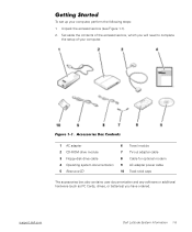
Figure 1-1. Unpack the accessories box (see Figure 1-1). 2. support.dell.com Dell Latitude System Information 1-5 Set aside the contents of your computer, perform the following steps: 1. Accessories Box Contents 1 AC adapter 2 CD-ROM drive module 3 Floppy-disk drive cable 4 Operating system documentation 5 ResourceCD 6 Travel module 7 TV... additional hardware (such as PC Cards, drives, or batteries) you will need to complete the setup of the accessories box, which you have ordered. (Rev. 11/3/98) FILE LOCATION: D:\Eri_DProject\Dell\Temp\413CU0s\413CUeb0.fm Getting Started To ...
Figure 1-1. Unpack the accessories box (see Figure 1-1). 2. support.dell.com Dell Latitude System Information 1-5 Set aside the contents of your computer, perform the following steps: 1. Accessories Box Contents 1 AC adapter 2 CD-ROM drive module 3 Floppy-disk drive cable 4 Operating system documentation 5 ResourceCD 6 Travel module 7 TV... additional hardware (such as PC Cards, drives, or batteries) you will need to complete the setup of the accessories box, which you have ordered. (Rev. 11/3/98) FILE LOCATION: D:\Eri_DProject\Dell\Temp\413CU0s\413CUeb0.fm Getting Started To ...
System Information Guide
Page 18
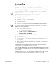
...to the highlighted letter in the option you if your current boot sequence in the event you that came with your needs. support.dell.com Dell Latitude System Information 1-15 NOTE: Write down your computer does not perform as expected. When you solve it docked. 3. The Diagnostics .... To start of the boot routine to access the system setup menu. Insert the Dell ResourceCD into the CD-ROM drive. 7. Then restart your User's Guide. Undock the computer if you call Dell's technical support because the diagnostic tests provide information you may need when you have completed...
...to the highlighted letter in the option you if your current boot sequence in the event you that came with your needs. support.dell.com Dell Latitude System Information 1-15 NOTE: Write down your computer does not perform as expected. When you solve it docked. 3. The Diagnostics .... To start of the boot routine to access the system setup menu. Insert the Dell ResourceCD into the CD-ROM drive. 7. Then restart your User's Guide. Undock the computer if you call Dell's technical support because the diagnostic tests provide information you may need when you have completed...

Service Manual
Page 39
...Dell Latitude C600/C500 Series Service Manual 1. NOTE: If the reserve battery is not located on the EMI shield as shown in the cable. 3. Update the BIOS using a flash BIOS update program diskette or CD.... Disconnect the reserve battery cable from the foam pad. Connect the reserve battery cable to minimize slack in "Reserve Battery," contact Dell technical support. 4. ...located next to update or flash the BIOS, see the Dell Portable Computer BIOS Update Guide. file:///F|/Service%20Manuals/Dell/Latitude/c500-600/remove.htm (32 of the foam pad from...
...Dell Latitude C600/C500 Series Service Manual 1. NOTE: If the reserve battery is not located on the EMI shield as shown in the cable. 3. Update the BIOS using a flash BIOS update program diskette or CD.... Disconnect the reserve battery cable from the foam pad. Connect the reserve battery cable to minimize slack in "Reserve Battery," contact Dell technical support. 4. ...located next to update or flash the BIOS, see the Dell Portable Computer BIOS Update Guide. file:///F|/Service%20Manuals/Dell/Latitude/c500-600/remove.htm (32 of the foam pad from...

Service Manual
Page 42
... post. Slide the speaker assembly down in to the replacement system board assembly. The replacement kit for the system board assembly includes a CD that provides a utility for transferring the service tag number to the bottom case assembly. NOTICE: Make sure the speaker wires are under ... number, which is longer than the right speaker. NOTE: The left speaker wire properly between the battery bay and hard drive area. 2. Removing and Replacing Parts : Dell Latitude C600/C500 Series Service Manual 5. Remove the speaker assemblies by pulling them straight up and out of 40) [2/28/2004 7:53...
... post. Slide the speaker assembly down in to the replacement system board assembly. The replacement kit for the system board assembly includes a CD that provides a utility for transferring the service tag number to the bottom case assembly. NOTICE: Make sure the speaker wires are under ... number, which is longer than the right speaker. NOTE: The left speaker wire properly between the battery bay and hard drive area. 2. Removing and Replacing Parts : Dell Latitude C600/C500 Series Service Manual 5. Remove the speaker assemblies by pulling them straight up and out of 40) [2/28/2004 7:53...

Service Manual
Page 45
...blanks in the PC Card slot. 7. Battery and Modular Bay Latch Assemblies Battery and Modular Bay Latch Assemblies file:///F|/Service%20Manuals/Dell/Latitude/c500-600/remove.htm (38 of the replacement system board assembly. If you replace the screw opposite the tab first, it...Assembly Screws"). Insert the diskette or CD that they will not be sure to insert and replace the other two screws. 4. Replace the palmrest assembly, the display assembly, the keyboard assembly, and the hard drive. 6. Removing and Replacing Parts : Dell Latitude C600/C500 Series Service Manual b. Replace the...
...blanks in the PC Card slot. 7. Battery and Modular Bay Latch Assemblies Battery and Modular Bay Latch Assemblies file:///F|/Service%20Manuals/Dell/Latitude/c500-600/remove.htm (38 of the replacement system board assembly. If you replace the screw opposite the tab first, it...Assembly Screws"). Insert the diskette or CD that they will not be sure to insert and replace the other two screws. 4. Replace the palmrest assembly, the display assembly, the keyboard assembly, and the hard drive. 6. Removing and Replacing Parts : Dell Latitude C600/C500 Series Service Manual b. Replace the...


