

Service Manual
Page 1
..., and Latitude are trademarks of Dell Inc.; All rights reserved. Bluetooth is strictly forbidden. Dell™ Latitude™ D610 Service Manual Before You Begin System Components Internal Card With Bluetooth® Wireless Technology Hard Drive Center Control Cover Keyboard Memory Module, Modem, and Devices Coin-Cell Battery Mini PCI Card Display Assembly and...
..., and Latitude are trademarks of Dell Inc.; All rights reserved. Bluetooth is strictly forbidden. Dell™ Latitude™ D610 Service Manual Before You Begin System Components Internal Card With Bluetooth® Wireless Technology Hard Drive Center Control Cover Keyboard Memory Module, Modem, and Devices Coin-Cell Battery Mini PCI Card Display Assembly and...
Service Manual
Page 2
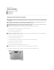
...docking device, undock it. 5. Slide and hold the power button for 4 seconds. 4. Back to Contents Page Before You Begin Dell™ Latitude™ D610 Service Manual Preparing to Work Inside the Computer Recommended Tools Computer Orientation Screw Identification Preparing to Work Inside ... disconnect any work surface is connected to prevent scratching the computer cover. 2. Remove any of the computer, and then remove the battery from the electrical outlet. 6. Ensure that the computer is not covered by its pins. Disconnect all attached devices. Save any attached...
...docking device, undock it. 5. Slide and hold the power button for 4 seconds. 4. Back to Contents Page Before You Begin Dell™ Latitude™ D610 Service Manual Preparing to Work Inside the Computer Recommended Tools Computer Orientation Screw Identification Preparing to Work Inside ... disconnect any work surface is connected to prevent scratching the computer cover. 2. Remove any of the computer, and then remove the battery from the electrical outlet. 6. Ensure that the computer is not covered by its pins. Disconnect all attached devices. Save any attached...
Service Manual
Page 3
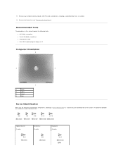
Remove the hard drive (see "Removing the Hard Drive"). 11. Remove any installed memory modules, Mini PCI cards, and devices, including a second battery if one is installed. 12. Optional Device: (1 each) Hard Drive: (2 each) Keyboard: (2 each) The placemat provides the number of the screws. Recommended Tools The procedures ...
Remove the hard drive (see "Removing the Hard Drive"). 11. Remove any installed memory modules, Mini PCI cards, and devices, including a second battery if one is installed. 12. Optional Device: (1 each) Hard Drive: (2 each) Keyboard: (2 each) The placemat provides the number of the screws. Recommended Tools The procedures ...
Service Manual
Page 5
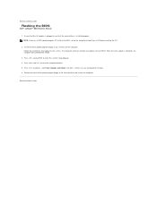
Ensure that the AC adapter is plugged in and that appear on the computer. The computer continues to Contents Page Flashing the BIOS Dell™ Latitude™ D610 Service Manual 1. Back to boot and updates the new BIOS. NOTE: If you use a BIOS update program ...update program floppy or CD from a CD before inserting the CD. 2. Back to enter the system setup program. 4. Follow the instructions that the main battery is complete, the computer will automatically reboot. 3. Press and to save configuration changes. 6. Press , select Save changes and reboot, and press to reset...
Ensure that the AC adapter is plugged in and that appear on the computer. The computer continues to Contents Page Flashing the BIOS Dell™ Latitude™ D610 Service Manual 1. Back to boot and updates the new BIOS. NOTE: If you use a BIOS update program ...update program floppy or CD from a CD before inserting the CD. 2. Back to enter the system setup program. 4. Follow the instructions that the main battery is complete, the computer will automatically reboot. 3. Press and to save configuration changes. 6. Press , select Save changes and reboot, and press to reset...
Service Manual
Page 6
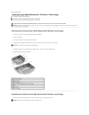
...cable connector 2 card connector 3 plastic brackets (2) 4 internal card with the card from the computer. Back to Contents Page Internal Card With Bluetooth® Wireless Technology Dell™ Latitude™ D610 Service Manual Removing the Internal Card With Bluetooth® Wireless Technology Installing the Internal Card With Bluetooth® Wireless Technology CAUTION... connector, press down the lever gently to break the plastic when closing the door. Follow the instructions in your Product Information Guide. Remove the battery. 3. NOTICE: Be careful not to avoid damaging it. 5.
...cable connector 2 card connector 3 plastic brackets (2) 4 internal card with the card from the computer. Back to Contents Page Internal Card With Bluetooth® Wireless Technology Dell™ Latitude™ D610 Service Manual Removing the Internal Card With Bluetooth® Wireless Technology Installing the Internal Card With Bluetooth® Wireless Technology CAUTION... connector, press down the lever gently to break the plastic when closing the door. Follow the instructions in your Product Information Guide. Remove the battery. 3. NOTICE: Be careful not to avoid damaging it. 5.

Service Manual
Page 7
Replace the battery. 2. Connect the card to Contents Page Back to the card cable connector, slide the door with the card into the card compartment, and gently press the door into position. 3.
Replace the battery. 2. Connect the card to Contents Page Back to the card cable connector, slide the door with the card into the card compartment, and gently press the door into position. 3.
Service Manual
Page 8
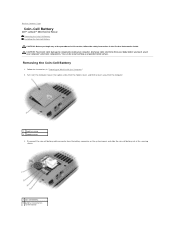
... Follow the instructions in the Product Information Guide. Back to Contents Page Coin-Cell Battery Dell™ Latitude™ D610 Service Manual Removing the Coin-Cell Battery Installing the Coin-Cell Battery CAUTION: Before you touch any of the procedures in this section, follow the safety ...any of your computer, discharge static electricity from the battery connector on the system board, and slide the coin-cell battery out of the securing sleeve. 1 coin-cell battery 2 battery connector on system board Removing the Coin-Cell Battery 1. Turn over the computer, loosen the captive ...
... Follow the instructions in the Product Information Guide. Back to Contents Page Coin-Cell Battery Dell™ Latitude™ D610 Service Manual Removing the Coin-Cell Battery Installing the Coin-Cell Battery CAUTION: Before you touch any of the procedures in this section, follow the safety ...any of your computer, discharge static electricity from the battery connector on the system board, and slide the coin-cell battery out of the securing sleeve. 1 coin-cell battery 2 battery connector on system board Removing the Coin-Cell Battery 1. Turn over the computer, loosen the captive ...

Service Manual
Page 9
Replace the modem cover. Connect the coin-cell battery cable connector to Contents Page Back to the battery connector on the system board. 2. 3 coin-cell battery cable connector 4 securing sleeve Installing the Coin-Cell Battery 1. Slide the battery into the securing sleeve. 3.
Replace the modem cover. Connect the coin-cell battery cable connector to Contents Page Back to the battery connector on the system board. 2. 3 coin-cell battery cable connector 4 securing sleeve Installing the Coin-Cell Battery 1. Slide the battery into the securing sleeve. 3.

Service Manual
Page 16
... (4) 8. Tighten the four M2 x 3-mm screws (two on the computer. Removing the Display Latch 1. Remove the display panel from electrical outlets, and remove any installed batteries. Installing the Display Panel 1. Replace the display panel inside the top cover. 4. Follow the instructions in both sides of the top display cable connector, and...
... (4) 8. Tighten the four M2 x 3-mm screws (two on the computer. Removing the Display Latch 1. Remove the display panel from electrical outlets, and remove any installed batteries. Installing the Display Panel 1. Replace the display panel inside the top cover. 4. Follow the instructions in both sides of the top display cable connector, and...
Service Manual
Page 35
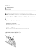
...-cooling assembly (see "Removing the Palm Rest"). 6. Back to Contents Page System Board Dell™ Latitude™ D610 Service Manual Removing the System Board Installing the System Board Removing the System Board CAUTION: Before you begin any installed batteries. Remove the palm rest (see "Removing the Microprocessor Thermal-Cooling Assembly"). 8. Remove the...
...-cooling assembly (see "Removing the Palm Rest"). 6. Back to Contents Page System Board Dell™ Latitude™ D610 Service Manual Removing the System Board Installing the System Board Removing the System Board CAUTION: Before you begin any installed batteries. Remove the palm rest (see "Removing the Microprocessor Thermal-Cooling Assembly"). 8. Remove the...
Service Manual
Page 38
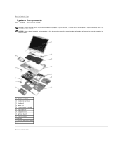
.... 1 display assembly 2 center control cover 3 keyboard 4 palm rest 5 system board assembly 6 optical device 7 computer base 8 primary battery 9 coin-cell battery 10 modem 11 thermal cooling assembly 12 hard drive Back to Contents Page System Components Dell™ Latitude™ D610 Service Manual NOTICE: Only a certified service technician should perform repairs on your warranty...
.... 1 display assembly 2 center control cover 3 keyboard 4 palm rest 5 system board assembly 6 optical device 7 computer base 8 primary battery 9 coin-cell battery 10 modem 11 thermal cooling assembly 12 hard drive Back to Contents Page System Components Dell™ Latitude™ D610 Service Manual NOTICE: Only a certified service technician should perform repairs on your warranty...
Service Manual
Page 39
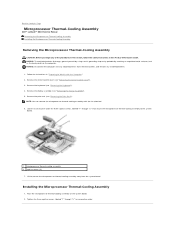
... safety instructions in "Preparing to Work Inside the Computer." 2. Back to Contents Page Microprocessor Thermal-Cooling Assembly Dell™ Latitude™ D610 Service Manual Removing the Microprocessor Thermal-Cooling Assembly Installing the Microprocessor Thermal-Cooling Assembly Removing... the Microprocessor Thermal-Cooling Assembly CAUTION: Before you begin any installed batteries. 1. Remove the display assembly (see "Removing the Palm Rest"). Remove the palm rest (see "Removing the Display...
... safety instructions in "Preparing to Work Inside the Computer." 2. Back to Contents Page Microprocessor Thermal-Cooling Assembly Dell™ Latitude™ D610 Service Manual Removing the Microprocessor Thermal-Cooling Assembly Installing the Microprocessor Thermal-Cooling Assembly Removing... the Microprocessor Thermal-Cooling Assembly CAUTION: Before you begin any installed batteries. 1. Remove the display assembly (see "Removing the Palm Rest"). Remove the palm rest (see "Removing the Display...

Service Manual
Page 44
..."Preparing to close may damage your computer's electronic components. Turn the computer over, and loosen the captive screw on the computer. Insert the battery into the connector, and rotate the module down until you do so by their edges, and avoid touching pins and contacts. Modem CAUTION: ...prevent static damage to components inside your computer, discharge static electricity from your body before you begin any of the module firmly into the battery bay, or connect the AC adapter to close , remove the module and reinstall it. Forcing the cover to your finger under the ...
..."Preparing to close may damage your computer's electronic components. Turn the computer over, and loosen the captive screw on the computer. Insert the battery into the connector, and rotate the module down until you do so by their edges, and avoid touching pins and contacts. Modem CAUTION: ...prevent static damage to components inside your computer, discharge static electricity from your body before you begin any of the module firmly into the battery bay, or connect the AC adapter to close , remove the module and reinstall it. Forcing the cover to your finger under the ...


