Product Manual
Page 3
... Erase FLASH Sectors...47 Password Recovery ...48 WLAN Licence Key ...48 Getting Started...51 Starting the D-Link Embedded Web Interface 52 Understanding the D-Link Embedded Web Interface 54 Device Representation...55 Using the D-Link Embedded Web Interface Management Buttons 56 Using Screen and Table Options 57 Adding Configuration Information ...57 Modifying ... Stack Topology 72 Stacking Failover Topology...72 Stacking Members and Unit ID ...72 Removing and Replacing Stacking Members 73 Exchanging Stacking Members...74 Switching the Stacking Master ...74 Configuring Stacking ...75 Page 2
... Erase FLASH Sectors...47 Password Recovery ...48 WLAN Licence Key ...48 Getting Started...51 Starting the D-Link Embedded Web Interface 52 Understanding the D-Link Embedded Web Interface 54 Device Representation...55 Using the D-Link Embedded Web Interface Management Buttons 56 Using Screen and Table Options 57 Adding Configuration Information ...57 Modifying ... Stack Topology 72 Stacking Failover Topology...72 Stacking Members and Unit ID ...72 Removing and Replacing Stacking Members 73 Exchanging Stacking Members...74 Switching the Stacking Master ...74 Configuring Stacking ...75 Page 2
Product Manual
Page 7
... ...308 Defining RMON Alarms...315 Appendix A, WLAN Country Settings 317 Appendix B, Device Specifications & Features 325 Appendix B, Troubleshooting 333 Problem Management...334 Troubleshooting Solutions...334 Contacting D-Link Technical Support 337 Warranty...365 Product Registration...369 International Offices ...371 Page 6
... ...308 Defining RMON Alarms...315 Appendix A, WLAN Country Settings 317 Appendix B, Device Specifications & Features 325 Appendix B, Troubleshooting 333 Problem Management...334 Troubleshooting Solutions...334 Contacting D-Link Technical Support 337 Warranty...365 Product Registration...369 International Offices ...371 Page 6
Product Manual
Page 8
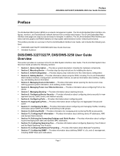
... Guide Overview Preface The Embedded Web System (EWS) is a network management system. The D-Link Web System Interface User Guide provides the following sections: • DXS/DWS-3227/3227P, DXS/DWS-3250 User Guide Overview • Intended Audience DXS/DWS-3227/3227P, DXS/DWS-3250 User Guide Overview This section provides an overview to -navigate. Provides information about...
... Guide Overview Preface The Embedded Web System (EWS) is a network management system. The D-Link Web System Interface User Guide provides the following sections: • DXS/DWS-3227/3227P, DXS/DWS-3250 User Guide Overview • Intended Audience DXS/DWS-3227/3227P, DXS/DWS-3250 User Guide Overview This section provides an overview to -navigate. Provides information about...
Product Manual
Page 10
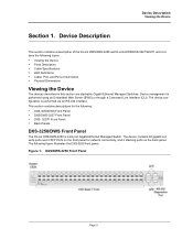
... a 48 port Gigabit Ethernet Managed Switch. This section contains descriptions for network connectivity, and 2 stacking ports on the front panel for the following: • DXS-3250/DWS Front Panel • DXS/DWS-3227 Front Panel • DXS- 3227P Front Panel • Back Panels DXS-3250/DWS Front Panel The D-Link DXS/DWS-3250 is performed via an...
... a 48 port Gigabit Ethernet Managed Switch. This section contains descriptions for network connectivity, and 2 stacking ports on the front panel for the following: • DXS-3250/DWS Front Panel • DXS/DWS-3227 Front Panel • DXS- 3227P Front Panel • Back Panels DXS-3250/DWS Front Panel The D-Link DXS/DWS-3250 is performed via an...
Product Manual
Page 11
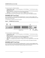
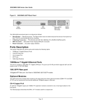
nated as 10/100/1000Base-T . An asynchronous serial console port supporting the RS-232 electrical specification. DXS/DWS-3227 Front Panel The D-Link DXS-3227 is a 24 port Gigabit Ethernet Managed Switch. The device contains 24 gigabit network ports, 4 SFP ports and 1XFP 10G port on the front panel for 10 Gigabit, Fibre Channel, Gigabit Ethernet...
nated as 10/100/1000Base-T . An asynchronous serial console port supporting the RS-232 electrical specification. DXS/DWS-3227 Front Panel The D-Link DXS-3227 is a 24 port Gigabit Ethernet Managed Switch. The device contains 24 gigabit network ports, 4 SFP ports and 1XFP 10G port on the front panel for 10 Gigabit, Fibre Channel, Gigabit Ethernet...
Product Manual
Page 13
... Series User Guide Figure 5: DXS/DWS-3227P Back Panel The DXS-3200 series back panel is an RJ-45 port which optional modules (DEM-411X and DEM411XT) can be inserted and then provide additional 10Gigabit copper or fiber port. The devices provide two stacking 12 Link(XG) interface ports. • RPS Connector... a 1000 Base-TX Gigabit 24/48 port. This it to avoid accidental device resetting. • 2 Stacking Connectors - DEM-411T expansion module is inserted in DXS/DWS-3227/3227P models. AC power supply interface. The port is configured as follows: • Reset Button -
... Series User Guide Figure 5: DXS/DWS-3227P Back Panel The DXS-3200 series back panel is an RJ-45 port which optional modules (DEM-411X and DEM411XT) can be inserted and then provide additional 10Gigabit copper or fiber port. The devices provide two stacking 12 Link(XG) interface ports. • RPS Connector... a 1000 Base-TX Gigabit 24/48 port. This it to avoid accidental device resetting. • 2 Stacking Connectors - DEM-411T expansion module is inserted in DXS/DWS-3227/3227P models. AC power supply interface. The port is configured as follows: • Reset Button -

Product Manual
Page 14
...to the modules bays located on the back panel. The following figure describes the DEM - 411X module used for high-speed Fiber Channel data links. Figure 6: CX-4 Expansion Module Device Description Ports Description 10G XFP Fiber port An optional 10Gigabit fiber port that can be removed and inserted... as 1000Base-X. Figure 7: XFP Expansion Module SFP Ports Small Form Factor Pluggable (SFP) Optical Transceivers are integrated duplex data mini-GBIC links for bi-directional communication over multimode optical fiber, designed for a fiber port: Transceivers can be purchased separately from...
...to the modules bays located on the back panel. The following figure describes the DEM - 411X module used for high-speed Fiber Channel data links. Figure 6: CX-4 Expansion Module Device Description Ports Description 10G XFP Fiber port An optional 10Gigabit fiber port that can be removed and inserted... as 1000Base-X. Figure 7: XFP Expansion Module SFP Ports Small Form Factor Pluggable (SFP) Optical Transceivers are integrated duplex data mini-GBIC links for bi-directional communication over multimode optical fiber, designed for a fiber port: Transceivers can be purchased separately from...
Product Manual
Page 17
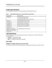
... UTP Cat. 5 (100 meters max.) EIA/TIA-568B 150-ohm STP (100 meters max.) 10Gigabit copper port (Up to the D-Link datasheet for the DXS/DWS-3200 series: Table 1: DXS-3250/DXS-3227P Cables and Optical Modules Specifications Cable Type 1000Base-T 10G CX-4 1000BASE-LX 1000BASE-SX 1000BASE-...LH 1000BASE-ZX 10Gigabit - Page 16 DXS/DWS 3200 Series User Guide Cable Specifications The following figure illustrates the DXS-3250 port LEDs. Indicate SFP port status. • System - Port ...
... UTP Cat. 5 (100 meters max.) EIA/TIA-568B 150-ohm STP (100 meters max.) 10Gigabit copper port (Up to the D-Link datasheet for the DXS/DWS-3200 series: Table 1: DXS-3250/DXS-3227P Cables and Optical Modules Specifications Cable Type 1000Base-T 10G CX-4 1000BASE-LX 1000BASE-SX 1000BASE-...LH 1000BASE-ZX 10Gigabit - Page 16 DXS/DWS 3200 Series User Guide Cable Specifications The following figure illustrates the DXS-3250 port LEDs. Indicate SFP port status. • System - Port ...
Product Manual
Page 18
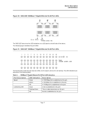
...transmission on the port. There is established on the port. No link is established on the left side of the device. The LED indications are described in the following figure illustrates the port LEDs: Figure 11: DXS-3227 1000Base-T Gigabit Ethernet RJ-45 Port LEDs The RJ-45 ports ...on the port. A 10-Mbps link is established on the port. Page 17 Device Description LED Definitions Figure 10: DXS-3250 1000Base...
...transmission on the port. There is established on the port. No link is established on the left side of the device. The LED indications are described in the following figure illustrates the port LEDs: Figure 11: DXS-3227 1000Base-T Gigabit Ethernet RJ-45 Port LEDs The RJ-45 ports ...on the port. A 10-Mbps link is established on the port. Page 17 Device Description LED Definitions Figure 10: DXS-3250 1000Base...
Product Manual
Page 19
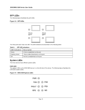
... transmission on the port. The following figure illustrates the port LEDs. System LEDs The three devices have one LED. No link is established on the left side of the device. DXS/DWS 3200 Series User Guide SFP LEDs The following figure illustrates the DXS-3250 system LEDs: Figure 13: DXS-3250 System...
... transmission on the port. The following figure illustrates the port LEDs. System LEDs The three devices have one LED. No link is established on the left side of the device. DXS/DWS 3200 Series User Guide SFP LEDs The following figure illustrates the DXS-3250 system LEDs: Figure 13: DXS-3250 System...
Product Manual
Page 20
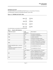
...device detected POST running POST. Link established on the port. There is designated as the stack Master. Device is data transmission on the port. The device is powered up . The following figure illustrates the DXS/DWS-3227/3227P system LEDs: Figure 14: DXS/DWS-3227/3227P LEDs The LED indications are... functioning correctly. All fans are described in on the left side of a stack (standalone). Link/Act for XG port P25/P26/P27 (DXS/DWS-3227/3227P) Link/Act for XG port MS PoE LED Indication Green Off Red Off Red Flashing Red Green Off Green Green Green...
...device detected POST running POST. Link established on the port. There is designated as the stack Master. Device is data transmission on the port. The device is powered up . The following figure illustrates the DXS/DWS-3227/3227P system LEDs: Figure 14: DXS/DWS-3227/3227P LEDs The LED indications are... functioning correctly. All fans are described in on the left side of a stack (standalone). Link/Act for XG port P25/P26/P27 (DXS/DWS-3227/3227P) Link/Act for XG port MS PoE LED Indication Green Off Red Off Red Flashing Red Green Off Green Green Green...
Product Manual
Page 27
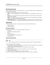
...place it on a clean flat surface and cut all packing material. 6. It is found missing or damaged, please contact your local D-Link reseller for unpacking the device, and includes the following topics: • Package Contents • Unpacking Essentials Package Contents While unpacking the ...wrist strap and attach the ESD clip to a metal surface to 104ºF) at a rel- Unpacking This section contains information for replacement. DXS/DWS 3200 Series User Guide Site Requirements The device is installed within 1.5 m (5 feet) of a grounded, easily accessible outlet 100-250 VAC, 50...
...place it on a clean flat surface and cut all packing material. 6. It is found missing or damaged, please contact your local D-Link reseller for unpacking the device, and includes the following topics: • Package Contents • Unpacking Essentials Package Contents While unpacking the ...wrist strap and attach the ESD clip to a metal surface to 104ºF) at a rel- Unpacking This section contains information for replacement. DXS/DWS 3200 Series User Guide Site Requirements The device is installed within 1.5 m (5 feet) of a grounded, easily accessible outlet 100-250 VAC, 50...
Product Manual
Page 32
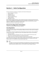
...Information Section 3. Performing other functions is performed. Auto-negotiation is performed completely within the physical layers during link initiation, without any additional overhead to take maximum advantage of their abilities • Acknowledge receipt and understanding...with the Web browser interface or CLI commands to operate in the following topics: • General Configuration Information • Booting the Switch • Configuration Overview • Advanced Configuration • Software Download and Reboot • Configuring Stacking • Startup Menu Functions ...
...Information Section 3. Performing other functions is performed. Auto-negotiation is performed completely within the physical layers during link initiation, without any additional overhead to take maximum advantage of their abilities • Acknowledge receipt and understanding...with the Web browser interface or CLI commands to operate in the following topics: • General Configuration Information • Booting the Switch • Configuration Overview • Advanced Configuration • Software Download and Reboot • Configuring Stacking • Startup Menu Functions ...
Product Manual
Page 35
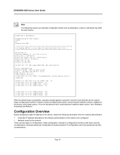
...:01:22 %INIT-I -Up: Vlan 1 01-Jan-200x 01:01:23 %LINK-W-Down: e4 . . . 01-Jan-200x 01:01:23 %LINK-W-Down: e46 01-Jan-200x 01:01:23 %LINK-W-Down: e47 01-Jan-200x 01:01:23 %LINK-W-Down: e48 After the switch boots successfully, a system prompt appears (console>) and the local terminal can... Back-to decompress... Decompressing SW from image-1 638000 OK Running from the network administrator: • A specific IP address allocated by the network administrator for the switch to be used to begin configuring the switch. DXS/DWS 3200 Series User Guide Note The following information from RAM...
...:01:22 %INIT-I -Up: Vlan 1 01-Jan-200x 01:01:23 %LINK-W-Down: e4 . . . 01-Jan-200x 01:01:23 %LINK-W-Down: e46 01-Jan-200x 01:01:23 %LINK-W-Down: e47 01-Jan-200x 01:01:23 %LINK-W-Down: e48 After the switch boots successfully, a system prompt appears (console>) and the local terminal can... Back-to decompress... Decompressing SW from image-1 638000 OK Running from the network administrator: • A specific IP address allocated by the network administrator for the switch to be used to begin configuring the switch. DXS/DWS 3200 Series User Guide Note The following information from RAM...

Product Manual
Page 52
Getting Started This section provides an introduction to the user interface, and includes the following topics: • Starting the D-Link Embedded Web Interface • Understanding the D-Link Embedded Web Interface • Using Screen and Table Options • Resetting the Device • Logging Off from the Device Page 51 Getting Started Section 4.
Getting Started This section provides an introduction to the user interface, and includes the following topics: • Starting the D-Link Embedded Web Interface • Understanding the D-Link Embedded Web Interface • Using Screen and Table Options • Resetting the Device • Logging Off from the Device Page 51 Getting Started Section 4.
Product Manual
Page 53
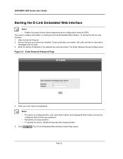
...blockers are enable, edit, add, and device information messages may not open. 3. Enter your user name and password. The D-Link Embedded Web Interface Home Page opens: Page 52 Click . The Enter Network Password Page opens: Figure 21: Enter Network Password Page 4. DXS.../DWS 3200 Series User Guide Starting the D-Link Embedded Web Interface Notes • Disable the popup blocker before beginning device configuration using the EWS. This section contains ...
...blockers are enable, edit, add, and device information messages may not open. 3. Enter your user name and password. The D-Link Embedded Web Interface Home Page opens: Page 52 Click . The Enter Network Password Page opens: Figure 21: Enter Network Password Page 4. DXS.../DWS 3200 Series User Guide Starting the D-Link Embedded Web Interface Notes • Disable the popup blocker before beginning device configuration using the EWS. This section contains ...
Product Manual
Page 54
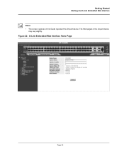
The Web pages in this Guide represent the 48 port device. Figure 22: D-Link Embedded Web Interface Home Page Page 53 Getting Started Starting the D-Link Embedded Web Interface Notes • The screen captures in the 24 port device may vary slightly.
The Web pages in this Guide represent the 48 port device. Figure 22: D-Link Embedded Web Interface Home Page Page 53 Getting Started Starting the D-Link Embedded Web Interface Notes • The screen captures in the 24 port device may vary slightly.
Product Manual
Page 55
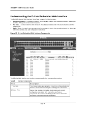
... Device View provides information about device ports, current configuration and status, table information, and feature components. Page 54 Figure 23: D-Link Embedded Web Interface Components The following views: • Port LED Indicators - Located in the main part of the home page, the.... Device View also displays other device information and dialog boxes for configuring parameters. DXS/DWS 3200 Series User Guide Understanding the D-Link Embedded Web Interface The D-Link Embedded Web Interface Home Page contains the following table lists the user interface components with their...
... Device View provides information about device ports, current configuration and status, table information, and feature components. Page 54 Figure 23: D-Link Embedded Web Interface Components The following views: • Port LED Indicators - Located in the main part of the home page, the.... Device View also displays other device information and dialog boxes for configuring parameters. DXS/DWS 3200 Series User Guide Understanding the D-Link Embedded Web Interface The D-Link Embedded Web Interface Home Page contains the following table lists the user interface components with their...
Product Manual
Page 56
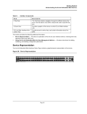
... Interface runs. Provide access to view all the components under a specific feature. Device Representation The D-Link Embedded Web Interface Home Page contains a graphical panel representation of the device. This section provides the following ... 55 Provides instructions for adding, modifying, and deleting configuration parameters. Getting Started Understanding the D-Link Embedded Web Interface Table 9: Interface Components View 3 Tab Area 4 Zoom View 5 D-Link Web Interface Information Tabs Description The Tab Area enables navigation through the different device features. Click...
... Interface runs. Provide access to view all the components under a specific feature. Device Representation The D-Link Embedded Web Interface Home Page contains a graphical panel representation of the device. This section provides the following ... 55 Provides instructions for adding, modifying, and deleting configuration parameters. Getting Started Understanding the D-Link Embedded Web Interface Table 9: Interface Components View 3 Tab Area 4 Zoom View 5 D-Link Web Interface Information Tabs Description The Tab Area enables navigation through the different device features. Click...
Product Manual
Page 57
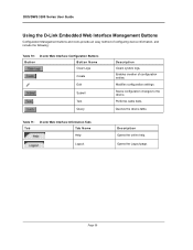
... Create Edit Submit Test Query Description Clears system logs. Opens the Logout page. Modifies configuration settings. Page 56 Queries the device table. Table 11: Ta b D-Link Web Interface Information Tabs Tab Name Help Logout Description Opens the online help. Performs cable tests. Saves configuration changes to the device. DXS...
... Create Edit Submit Test Query Description Clears system logs. Opens the Logout page. Modifies configuration settings. Page 56 Queries the device table. Table 11: Ta b D-Link Web Interface Information Tabs Tab Name Help Logout Description Opens the online help. Performs cable tests. Saves configuration changes to the device. DXS...


