
Hardware Installation Guide
Page 4
... SFP Modules into SFP Module Slots 2-16 Removing SFP Modules from the Switch 2-8 Attaching Brackets to the Catalyst 3560 Switch 2-8 Mounting the Switch in a Rack 2-10 Attaching the Cable Guide 2-11 Wall-Mounting 2-12 Attaching the Brackets to Go Next 2-24 Switch Installation (8- and 12-Port Switches) 3-1 Preparing for Wall Mounting 2-12 Attaching the RPS Connector Cover 2-13...
... SFP Modules into SFP Module Slots 2-16 Removing SFP Modules from the Switch 2-8 Attaching Brackets to the Catalyst 3560 Switch 2-8 Mounting the Switch in a Rack 2-10 Attaching the Cable Guide 2-11 Wall-Mounting 2-12 Attaching the Brackets to Go Next 2-24 Switch Installation (8- and 12-Port Switches) 3-1 Preparing for Wall Mounting 2-12 Attaching the RPS Connector Cover 2-13...

Hardware Installation Guide
Page 11
... 1-3 • Rear Panel Description, page 1-15 • Management Options, page 1-20 Setting Up the Switch See the Catalyst 3560 Switch Getting Started Guide for an optional Cisco RPS 2300 or Cisco RPS 675 that operates on setting up your Catalyst switch. and 12-port switches include connections for instructions on how to use Express Setup to initially configure your...
... 1-3 • Rear Panel Description, page 1-15 • Management Options, page 1-20 Setting Up the Switch See the Catalyst 3560 Switch Getting Started Guide for an optional Cisco RPS 2300 or Cisco RPS 675 that operates on setting up your Catalyst switch. and 12-port switches include connections for instructions on how to use Express Setup to initially configure your...

Hardware Installation Guide
Page 12
... • 1000BASE-T (only Catalyst 3560 24- The Catalyst 3560-8PC and the Catalyst 3560-12PC-S switches are smaller than the other Catalyst 3560 switches. Supported SFP modules: • 100BASE-BX10 (only Catalyst 3560 8- and 12-port switches) • 100BASE-FX • 100BASE-LX (only Catalyst 3560 8- Features Chapter 1 Product Overview Table 1-1 Catalyst 3560 Switch Model Descriptions Switch Model Description FastEthernet Catalyst 3560-24PS 24 10/100 Power...
... • 1000BASE-T (only Catalyst 3560 24- The Catalyst 3560-8PC and the Catalyst 3560-12PC-S switches are smaller than the other Catalyst 3560 switches. Supported SFP modules: • 100BASE-BX10 (only Catalyst 3560 8- and 12-port switches) • 100BASE-FX • 100BASE-LX (only Catalyst 3560 8- Features Chapter 1 Product Overview Table 1-1 Catalyst 3560 Switch Model Descriptions Switch Model Description FastEthernet Catalyst 3560-24PS 24 10/100 Power...

Hardware Installation Guide
Page 13
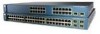
... 2. Figure 1-1 Catalyst 3560-24PS and 3560V2-24PS Switch Front Panel OL-6337-07 97912 SYST RPS STAT DUPLX SPEED PoE MODE 12 1X 34 56 78 9 10 11 12 11X 2X 12X 13 14 13X 15 16 17 18 19 20 21 22 23 24 Catalyst 3560 SERIES PoE-24 23X 14X 24X 1 2 1 2 1 10/100 PoE ports 2 SFP... module slots Catalyst 3560 Switch...
... 2. Figure 1-1 Catalyst 3560-24PS and 3560V2-24PS Switch Front Panel OL-6337-07 97912 SYST RPS STAT DUPLX SPEED PoE MODE 12 1X 34 56 78 9 10 11 12 11X 2X 12X 13 14 13X 15 16 17 18 19 20 21 22 23 24 Catalyst 3560 SERIES PoE-24 23X 14X 24X 1 2 1 2 1 10/100 PoE ports 2 SFP... module slots Catalyst 3560 Switch...

Hardware Installation Guide
Page 15
...23 24 25 26 27 28 29 30 31 32 16X 18X 33 31X 33X 34 35 36 37 38 39 40 41 42 43 44 45 46 47 48 47X 32X 34X Catalyst 3560 SERIES 1 3 48X 2 4 1 2 1 10/100 ports 2 SFP module slots The console port, 10/100 PoE ports,...6x 7x 8x Catalyst 2960 Series 1 157822 1 2 3 1 Console port 2 10/100 PoE ports 3 Dual-purpose port OL-6337-07 Catalyst 3560 Switch Hardware Installation Guide 1-5 The first member of the Catalyst 3560-8PC switch and the Catalyst 3560-12PC-S switch (Figure 1-5 and Figure 1-6). Port 3 is above port 4, and so on. The dual-purpose port can use either...
...23 24 25 26 27 28 29 30 31 32 16X 18X 33 31X 33X 34 35 36 37 38 39 40 41 42 43 44 45 46 47 48 47X 32X 34X Catalyst 3560 SERIES 1 3 48X 2 4 1 2 1 10/100 ports 2 SFP module slots The console port, 10/100 PoE ports,...6x 7x 8x Catalyst 2960 Series 1 157822 1 2 3 1 Console port 2 10/100 PoE ports 3 Dual-purpose port OL-6337-07 Catalyst 3560 Switch Hardware Installation Guide 1-5 The first member of the Catalyst 3560-8PC switch and the Catalyst 3560-12PC-S switch (Figure 1-5 and Figure 1-6). Port 3 is above port 4, and so on. The dual-purpose port can use either...

Hardware Installation Guide
Page 16
Port 3 is above port 4, and so on the left, as shown in pairs. Figure 1-7 Catalyst 3560G-24PS Switch Front Panel 119676 SYST RPS STAT DUPLX SPEED PoE MODE 12 1X 34 56 78 9 10 11 12 11X 2X 12X 13 14 13X 15 16 17 18 19 20 21 22 23 24 Catalyst 3560G SERIES PoE-24 23X 25... 14X 27 24X 26 28 1 2 1 10/100/1000 ports 2 SFP module slots Catalyst...
Port 3 is above port 4, and so on the left, as shown in pairs. Figure 1-7 Catalyst 3560G-24PS Switch Front Panel 119676 SYST RPS STAT DUPLX SPEED PoE MODE 12 1X 34 56 78 9 10 11 12 11X 2X 12X 13 14 13X 15 16 17 18 19 20 21 22 23 24 Catalyst 3560G SERIES PoE-24 23X 25... 14X 27 24X 26 28 1 2 1 10/100/1000 ports 2 SFP module slots Catalyst...

Hardware Installation Guide
Page 17
... 20 21 22 23 24 23X Catalyst 3560G SERIES 25 14X 27 24X 26 28 1 2 1 10/100/1000 ports 2 SFP module slots The 10/100/1000 PoE ports on . The first member of the pair (port 1) is above port 4, and so on the Catalyst 3560G-48PS switch are numbered 25 to 52. Figure 1-9 Catalyst 3560G-48PS Switch Front Panel 119674...
... 20 21 22 23 24 23X Catalyst 3560G SERIES 25 14X 27 24X 26 28 1 2 1 10/100/1000 ports 2 SFP module slots The 10/100/1000 PoE ports on . The first member of the pair (port 1) is above port 4, and so on the Catalyst 3560G-48PS switch are numbered 25 to 52. Figure 1-9 Catalyst 3560G-48PS Switch Front Panel 119674...

Hardware Installation Guide
Page 18
... 19 20 21 22 23 24 25 26 27 28 29 30 31 32 16X 18X 33 31X 33X 34 35 36 37 38 39 40 41 42 43 44 45 46 47 48 47X 32X 34X Catalyst 3560G SERIES 49 51 48X 50 52 1 2 1 10/100/1000 ports 2 SFP module slots 10... attached device supports it) and configures itself accordingly. A restricted access area can set the 10/100/1000 ports to 52. Front Panel Description Chapter 1 Product Overview The 10/100/1000 ports on the Catalyst 3560G-48TS switch are grouped in full duplex. • You can be within the restricted access location are made using...
... 19 20 21 22 23 24 25 26 27 28 29 30 31 32 16X 18X 33 31X 33X 34 35 36 37 38 39 40 41 42 43 44 45 46 47 48 47X 32X 34X Catalyst 3560G SERIES 49 51 48X 50 52 1 2 1 10/100/1000 ports 2 SFP module slots 10... attached device supports it) and configures itself accordingly. A restricted access area can set the 10/100/1000 ports to 52. Front Panel Description Chapter 1 Product Overview The 10/100/1000 ports on the Catalyst 3560G-48TS switch are grouped in full duplex. • You can be within the restricted access location are made using...

Hardware Installation Guide
Page 19
...be sure that the cable is enabled by default. On the Catalyst 3560-48PS, 3560G-48PS, and 3560V2-48PS switches, any 24 of the 48 10/100 or 10/100/1000 ports delivers 15.4 W of PoE, or any combination of the ports delivers an average of 7.7 W of PoE at the same...reboot or reestablish link with IEEE 802.3af and Cisco prestandard PoE support for Cisco IP Phones and Cisco Aironet Access Points. • Each of the Catalyst 3560-8PC, 3560-12PC-S, 3560-24PS, and 3560V2-24PS switch 10/100 ports or the Catalyst 3560G-24PS switch 10/100/1000 ports deliver up to a maximum power output of ...
...be sure that the cable is enabled by default. On the Catalyst 3560-48PS, 3560G-48PS, and 3560V2-48PS switches, any 24 of the 48 10/100 or 10/100/1000 ports delivers 15.4 W of PoE, or any combination of the ports delivers an average of 7.7 W of PoE at the same...reboot or reestablish link with IEEE 802.3af and Cisco prestandard PoE support for Cisco IP Phones and Cisco Aironet Access Points. • Each of the Catalyst 3560-8PC, 3560-12PC-S, 3560-24PS, and 3560V2-24PS switch 10/100 ports or the Catalyst 3560G-24PS switch 10/100/1000 ports deliver up to a maximum power output of ...
Hardware Installation Guide
Page 33
...Catalyst 3560 24- and 48-Port Switches) This chapter describes how to the switch. The instructions in this chapter for connecting to the switch ports and for installing, and connecting to the SFP modules apply to Go Next, page 2-24 Preparing for the Catalyst 3560-8PC and Catalyst 3560 12-PC-S switches, see Chapter 3, "Switch Installation (8- and 12-Port Switches...or 10/100/1000 Ports, page 2-19 • Connecting the Switch to Compatible Devices, page 2-20 • Where to all Catalyst 3560 switches. 2 C H A P T E R Switch Installation (24- and 48-port switches, including how to ...
...Catalyst 3560 24- and 48-Port Switches) This chapter describes how to the switch. The instructions in this chapter for connecting to the switch ports and for installing, and connecting to the SFP modules apply to Go Next, page 2-24 Preparing for the Catalyst 3560-8PC and Catalyst 3560 12-PC-S switches, see Chapter 3, "Switch Installation (8- and 12-Port Switches...or 10/100/1000 Ports, page 2-19 • Connecting the Switch to Compatible Devices, page 2-20 • Where to all Catalyst 3560 switches. 2 C H A P T E R Switch Installation (24- and 48-port switches, including how to ...
Hardware Installation Guide
Page 34
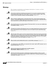
... inside the chassis; Statement 265 Warning Attach only the following Cisco RPS model to the system. Statement 43 Warning Do not ...conduct harmful levels of 113•F (45•C). and 48-Port Switches) Warnings These warnings are in place. Failure to use the...the Regulatory Compliance and Safety Information for Installation Chapter 2 Switch Installation (24- Do not operate the system unless all cards and faceplates... to the switch, install an RPS connector cover on the back of clearance around the ventilation openings. Statement 378 Catalyst 3560 Switch Hardware Installation...
... inside the chassis; Statement 265 Warning Attach only the following Cisco RPS model to the system. Statement 43 Warning Do not ...conduct harmful levels of 113•F (45•C). and 48-Port Switches) Warnings These warnings are in place. Failure to use the...the Regulatory Compliance and Safety Information for Installation Chapter 2 Switch Installation (24- Do not operate the system unless all cards and faceplates... to the switch, install an RPS connector cover on the back of clearance around the ventilation openings. Statement 378 Catalyst 3560 Switch Hardware Installation...

Hardware Installation Guide
Page 35
... unit in the fixed wiring. A restricted access area can be mounted at the bottom of security. Statement 1022 OL-6337-07 Catalyst 3560 Switch Hardware Installation Guide 2-3 Chapter 2 Switch Installation (24- and 48-Port Switches) Preparing for Installation Warning Do not work on the building's installation for installation in a rack, you must be incorporated in a partially...
... unit in the fixed wiring. A restricted access area can be mounted at the bottom of security. Statement 1022 OL-6337-07 Catalyst 3560 Switch Hardware Installation Guide 2-3 Chapter 2 Switch Installation (24- and 48-Port Switches) Preparing for Installation Warning Do not work on the building's installation for installation in a rack, you must be incorporated in a partially...

Hardware Installation Guide
Page 36
...danger. Statement 1071 Warning Voltages that suitable grounding is installed, the following ports must comply with standard practices for Installation Chapter 2 Switch Installation (24- Statement 1074 Catalyst 3560 Switch Hardware Installation Guide 2-4 OL-6337-07 Statement 1040 Warning For connections outside ...You are made first and disconnected last. Avoid using uninsulated exposed metal contacts, conductors, or terminals. and 48-Port Switches) Warning This equipment must be grounded. Statement 1024 Warning This unit might have more than one power supply ...
...danger. Statement 1071 Warning Voltages that suitable grounding is installed, the following ports must comply with standard practices for Installation Chapter 2 Switch Installation (24- Statement 1074 Catalyst 3560 Switch Hardware Installation Guide 2-4 OL-6337-07 Statement 1040 Warning For connections outside ...You are made first and disconnected last. Avoid using uninsulated exposed metal contacts, conductors, or terminals. and 48-Port Switches) Warning This equipment must be grounded. Statement 1024 Warning This unit might have more than one power supply ...

Hardware Installation Guide
Page 37
... cabling. - Chapter 2 Switch Installation (24- Installation Guidelines When you determine where to place the switch, be sure to observe these conditions: - When you might need to insert an inline optical attenuator in a closed or multirack assembly, the temperature around the unit does not exceed 113°F (45°C). Catalyst 3560 switch SFP ports use shorter lengths...
... cabling. - Chapter 2 Switch Installation (24- Installation Guidelines When you determine where to place the switch, be sure to observe these conditions: - When you might need to insert an inline optical attenuator in a closed or multirack assembly, the temperature around the unit does not exceed 113°F (45°C). Catalyst 3560 switch SFP ports use shorter lengths...

Hardware Installation Guide
Page 38
...shelf, you connect the RPS to the same AC power source. Warning Attach only the following Cisco RPS model to rack-mount the switch. Verifying Switch Operation Chapter 2 Switch Installation (24- Set the RPS to run Express Setup. Network Equipment Building Systems (NEBS) GR-63-CORE ... the "Cisco RPS" section on the switch, and connect the other particles, causing contaminant buildup inside the chassis, which can draw dust and other end of suspended particulate matter: - Statement 370 Catalyst 3560 Switch Hardware Installation Guide 2-6 OL-6337-07 and 48-Port Switches) When...
...shelf, you connect the RPS to the same AC power source. Warning Attach only the following Cisco RPS model to rack-mount the switch. Verifying Switch Operation Chapter 2 Switch Installation (24- Set the RPS to run Express Setup. Network Equipment Building Systems (NEBS) GR-63-CORE ... the "Cisco RPS" section on the switch, and connect the other particles, causing contaminant buildup inside the chassis, which can draw dust and other end of suspended particulate matter: - Statement 370 Catalyst 3560 Switch Hardware Installation Guide 2-6 OL-6337-07 and 48-Port Switches) When...
Hardware Installation Guide
Page 39
...Switch Installation (24- POST lasts approximately 1 minute. When the switch begins POST, the System, RPS, Status, Duplex, and Speed LEDs turn off and then reflect the switch operating status. The System LED blinks green, and the other LEDs turn green. Call Cisco...special precautions to the Catalyst 3560 Switch, page 2-8 • Mounting the Switch in a Rack,...Port Switches) Installing the Switch As the switch powers on a shelf as described in a 24-inch rack requires an optional bracket kit that the switch functions properly. POST failures are provided to ensure that contains the 24...
...Switch Installation (24- POST lasts approximately 1 minute. When the switch begins POST, the System, RPS, Status, Duplex, and Speed LEDs turn off and then reflect the switch operating status. The System LED blinks green, and the other LEDs turn green. Call Cisco...special precautions to the Catalyst 3560 Switch, page 2-8 • Mounting the Switch in a Rack,...Port Switches) Installing the Switch As the switch powers on a shelf as described in a 24-inch rack requires an optional bracket kit that the switch functions properly. POST failures are provided to ensure that contains the 24...

Hardware Installation Guide
Page 40
... bracket orientation and the brackets that you use bracket part number 700-13248-01. and 48-Port Switches) Removing Screws from the Catalyst 3560 Switch 97916 40 41 42 43 44 45 46 47 48 47X Catalyst 3560 SERIES PoE-48 1 3 48X 2 4 Attaching Brackets to the opposite side. Figure 2-2 1...inch racks, use bracket part number 700-8209-01 • For 24-inch racks, use depend on whether you install the switch in a rack, remove the switch chassis screws (see Figure 2-1.) Figure 2-1 Removing Screws from the Switch Before you are attaching the brackets for 19-Inch Racks to one...
... bracket orientation and the brackets that you use bracket part number 700-13248-01. and 48-Port Switches) Removing Screws from the Catalyst 3560 Switch 97916 40 41 42 43 44 45 46 47 48 47X Catalyst 3560 SERIES PoE-48 1 3 48X 2 4 Attaching Brackets to the opposite side. Figure 2-2 1...inch racks, use bracket part number 700-8209-01 • For 24-inch racks, use depend on whether you install the switch in a rack, remove the switch chassis screws (see Figure 2-1.) Figure 2-1 Removing Screws from the Switch Before you are attaching the brackets for 19-Inch Racks to one...
Hardware Installation Guide
Page 41
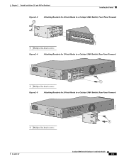
...Port Switches) Installing the Switch Figure 2-3 1 Attaching Brackets for 24-Inch Racks to a Catalyst 3560 Switch, Front Panel Forward 1 Phillips flat-head screws SYST RPS STAT DUPLX SPEED PoE MODE 1 1X 23 45 67 8 9 10 11 12 13 14 15 16 15X 2X 16X 97918 Figure 2-4 Attaching Brackets for 19-Inch Racks to a Catalyst 3560 Switch[email protected] 1 1 Phillips flat-head screws Figure 2-5 Attaching Brackets for 24-Inch Racks to a Catalyst 3560 Switch, Rear Panel Forward 97920 5.0A1-20R.05A-A2T,0IN500GV-6~0 HZ [email protected]...
...Port Switches) Installing the Switch Figure 2-3 1 Attaching Brackets for 24-Inch Racks to a Catalyst 3560 Switch, Front Panel Forward 1 Phillips flat-head screws SYST RPS STAT DUPLX SPEED PoE MODE 1 1X 23 45 67 8 9 10 11 12 13 14 15 16 15X 2X 16X 97918 Figure 2-4 Attaching Brackets for 19-Inch Racks to a Catalyst 3560 Switch[email protected] 1 1 Phillips flat-head screws Figure 2-5 Attaching Brackets for 24-Inch Racks to a Catalyst 3560 Switch, Rear Panel Forward 97920 5.0A1-20R.05A-A2T,0IN500GV-6~0 HZ [email protected]...
Hardware Installation Guide
Page 42
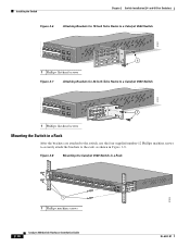
...Port Switches) Figure 2-6 Attaching Brackets for 19-Inch Telco Racks to a Catalyst 3560 Switch 97921 40 41 42 43 44 45 46 47 48 47X Catalyst 3560 SERIES PoE-48 1 3 48X 2 4 1 1 Phillips flat-head screws Figure 2-7 Attaching Brackets for 24-Inch Telco Racks to a Catalyst 3560 Switch 97922 40 41 42 43 44 45 46 47 48 47X Catalyst... 3560 SERIES PoE-48 1 3 48X 2 1 4 1 Phillips flat-head screws Mounting the Switch in a Rack After the brackets are attached to the switch,...
...Port Switches) Figure 2-6 Attaching Brackets for 19-Inch Telco Racks to a Catalyst 3560 Switch 97921 40 41 42 43 44 45 46 47 48 47X Catalyst 3560 SERIES PoE-48 1 3 48X 2 4 1 1 Phillips flat-head screws Figure 2-7 Attaching Brackets for 24-Inch Telco Racks to a Catalyst 3560 Switch 97922 40 41 42 43 44 45 46 47 48 47X Catalyst... 3560 SERIES PoE-48 1 3 48X 2 1 4 1 Phillips flat-head screws Mounting the Switch in a Rack After the brackets are attached to the switch,...
Hardware Installation Guide
Page 43
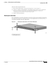
...Catalyst 3560 Switch Hardware Installation Guide 2-11 See the Catalyst 3560 Switch Getting Started Guide for instructions. Connect to prevent the cables from obscuring the front panel of the switch and the other devices installed in the rack. and 48-Port Switches) Installing the Switch After the switch... use the CLI setup program, see Appendix D, "Configuring the Switch with the CLI-Based Setup Program." 3. Chapter 2 Switch Installation (24- Figure 2-9 Attaching the Cable Guide on page 2-6. 2. Power on the switch. Attaching the Cable Guide We recommend that you attach the cable...
...Catalyst 3560 Switch Hardware Installation Guide 2-11 See the Catalyst 3560 Switch Getting Started Guide for instructions. Connect to prevent the cables from obscuring the front panel of the switch and the other devices installed in the rack. and 48-Port Switches) Installing the Switch After the switch... use the CLI setup program, see Appendix D, "Configuring the Switch with the CLI-Based Setup Program." 3. Chapter 2 Switch Installation (24- Figure 2-9 Attaching the Cable Guide on page 2-6. 2. Power on the switch. Attaching the Cable Guide We recommend that you attach the cable...


