
Hardware Installation Guide
Page 4
... Modules into SFP Module Slots 2-16 Removing SFP Modules from the Switch 2-8 Attaching Brackets to the Catalyst 3560 Switch 2-8 Mounting the Switch in a Rack 2-10 Attaching the Cable Guide 2-11 Wall-Mounting 2-12 Attaching the Brackets to Go Next 2-24 Switch Installation (8- and 12-Port Switches) 3-1 Preparing for Wall Mounting 2-12 Attaching the RPS Connector Cover 2-13...
... Modules into SFP Module Slots 2-16 Removing SFP Modules from the Switch 2-8 Attaching Brackets to the Catalyst 3560 Switch 2-8 Mounting the Switch in a Rack 2-10 Attaching the Cable Guide 2-11 Wall-Mounting 2-12 Attaching the Brackets to Go Next 2-24 Switch Installation (8- and 12-Port Switches) 3-1 Preparing for Wall Mounting 2-12 Attaching the RPS Connector Cover 2-13...

Hardware Installation Guide
Page 11
..., routers, and other network devices. OL-6337-07 Catalyst 3560 Switch Hardware Installation Guide 1-1 Features The 24- See the switch software configuration guide for an optional Cisco RPS 2300 or Cisco RPS 675 that operates on setting up your Catalyst switch. and 12-port switches include connections for examples of the Catalyst 3560 switch. This chapter provides a functional overview of how...
..., routers, and other network devices. OL-6337-07 Catalyst 3560 Switch Hardware Installation Guide 1-1 Features The 24- See the switch software configuration guide for an optional Cisco RPS 2300 or Cisco RPS 675 that operates on setting up your Catalyst switch. and 12-port switches include connections for examples of the Catalyst 3560 switch. This chapter provides a functional overview of how...

Hardware Installation Guide
Page 12
...; Coarse Wavelength-Division Multiplexing (CWDM) • SFP module patch cable. (CAB-SFP-50CM=.) Switches running Cisco IOS Release 12.2(25)SEB or later support this patch cable. Features Chapter 1 Product Overview Table 1-1 Catalyst 3560 Switch Model Descriptions Switch Model Description FastEthernet Catalyst 3560-24PS 24 10/100 Power over Ethernet (PoE) ports and 2 small form-factor pluggable (SFP...
...; Coarse Wavelength-Division Multiplexing (CWDM) • SFP module patch cable. (CAB-SFP-50CM=.) Switches running Cisco IOS Release 12.2(25)SEB or later support this patch cable. Features Chapter 1 Product Overview Table 1-1 Catalyst 3560 Switch Model Descriptions Switch Model Description FastEthernet Catalyst 3560-24PS 24 10/100 Power over Ethernet (PoE) ports and 2 small form-factor pluggable (SFP...

Hardware Installation Guide
Page 13
... slots are autonegotiated. Figure 1-1 Catalyst 3560-24PS and 3560V2-24PS Switch Front Panel OL-6337-07 97912 SYST RPS STAT DUPLX SPEED PoE MODE 12 1X 34 56 78 9 10 11 12 11X 2X 12X 13 14 13X 15 16 17 18 19 20 21 22 23 24 Catalyst 3560 SERIES PoE-24 23X 14X 24X 1 2 1 2 1 10.../100 PoE ports 2 SFP module slots Catalyst 3560 Switch...
... slots are autonegotiated. Figure 1-1 Catalyst 3560-24PS and 3560V2-24PS Switch Front Panel OL-6337-07 97912 SYST RPS STAT DUPLX SPEED PoE MODE 12 1X 34 56 78 9 10 11 12 11X 2X 12X 13 14 13X 15 16 17 18 19 20 21 22 23 24 Catalyst 3560 SERIES PoE-24 23X 14X 24X 1 2 1 2 1 10.../100 PoE ports 2 SFP module slots Catalyst 3560 Switch...

Hardware Installation Guide
Page 14
...-24TS-S, 3560V2-24TS, and 3560V2-24TS-SD Switch Front Panel 126808 SYST RPS STAT DUPLX SPEED MODE 12 1X 34 56 78 9 10 11 12 11X 2X 12X 13 14 13X 15 16 17 18 19 20 21 22 23 24 23X Catalyst 3560 SERIES 14X 24X 1 2 1 2 1 10/100 ports 2 SFP module slots... The 10/100 PoE ports on the switch are grouped in pairs. Figure 1-3 Catalyst 3560-48PS and 3560V2-48PS Switch Front Panel 97911 SYST RPS STAT DUPLX SPEED PoE MODE 1 1X...
...-24TS-S, 3560V2-24TS, and 3560V2-24TS-SD Switch Front Panel 126808 SYST RPS STAT DUPLX SPEED MODE 12 1X 34 56 78 9 10 11 12 11X 2X 12X 13 14 13X 15 16 17 18 19 20 21 22 23 24 23X Catalyst 3560 SERIES 14X 24X 1 2 1 2 1 10/100 ports 2 SFP module slots... The 10/100 PoE ports on the switch are grouped in pairs. Figure 1-3 Catalyst 3560-48PS and 3560V2-48PS Switch Front Panel 97911 SYST RPS STAT DUPLX SPEED PoE MODE 1 1X...

Hardware Installation Guide
Page 15
...SPD MODE CONSOLE 1x 2x 3x 4x 5x 6x 7x 8x Catalyst 2960 Series 1 157822 1 2 3 1 Console port 2 10/100 PoE ports 3 Dual-purpose port OL-6337-07 Catalyst 3560 Switch Hardware Installation Guide 1-5 Figure 1-4 Catalyst 3560-48TS-S and 3560V2-48TS Switch Front Panel 126807 SYST RPS STAT DUPLX SPEED MODE 1 1X... 2X 23 45 67 8 9 10 11 12 13 14 15 16 17 15X 17X 18 19 20 21 22 23 24 25 26 27...
...SPD MODE CONSOLE 1x 2x 3x 4x 5x 6x 7x 8x Catalyst 2960 Series 1 157822 1 2 3 1 Console port 2 10/100 PoE ports 3 Dual-purpose port OL-6337-07 Catalyst 3560 Switch Hardware Installation Guide 1-5 Figure 1-4 Catalyst 3560-48TS-S and 3560V2-48TS Switch Front Panel 126807 SYST RPS STAT DUPLX SPEED MODE 1 1X... 2X 23 45 67 8 9 10 11 12 13 14 15 16 17 15X 17X 18 19 20 21 22 23 24 25 26 27...

Hardware Installation Guide
Page 16
... port Gigabit Ethernet Switch Front Panel Descriptions • Catalyst 3560G-24PS Switch Front Panel, Figure 1-7 on page 1-6 • Catalyst 3560G-24TS Switch Front Panel, Figure 1-8 on page 1-7 • Catalyst 3560G-48PS Switch Front Panel, Figure 1-9 on page 1-7 • Catalyst 3560G-48TS Switch Front Panel, Figure...24PS Switch Front Panel 119676 SYST RPS STAT DUPLX SPEED PoE MODE 12 1X 34 56 78 9 10 11 12 11X 2X 12X 13 14 13X 15 16 17 18 19 20 21 22 23 24 Catalyst 3560G SERIES PoE-24 23X 25 14X 27 24X 26 28 1 2 1 10/100/1000 ports 2 SFP module slots Catalyst...
... port Gigabit Ethernet Switch Front Panel Descriptions • Catalyst 3560G-24PS Switch Front Panel, Figure 1-7 on page 1-6 • Catalyst 3560G-24TS Switch Front Panel, Figure 1-8 on page 1-7 • Catalyst 3560G-48PS Switch Front Panel, Figure 1-9 on page 1-7 • Catalyst 3560G-48TS Switch Front Panel, Figure...24PS Switch Front Panel 119676 SYST RPS STAT DUPLX SPEED PoE MODE 12 1X 34 56 78 9 10 11 12 11X 2X 12X 13 14 13X 15 16 17 18 19 20 21 22 23 24 Catalyst 3560G SERIES PoE-24 23X 25 14X 27 24X 26 28 1 2 1 10/100/1000 ports 2 SFP module slots Catalyst...

Hardware Installation Guide
Page 17
... Installation Guide 1-7 Figure 1-8 Catalyst 3560G-24TS Switch Front Panel 119677 SYST RPS STAT DUPLX SPEED MODE 12 1X 34 56 78 9 10 11 12 11X 2X 12X 13 14 13X 15 16 17 18 19 20 21 22 23 24 23X Catalyst 3560G SERIES 25 14X 27 24X 26 28 1 2 1 10/100/1000 ports... 2 SFP module slots The 10/100/1000 PoE ports on the Catalyst 3560G-48PS switch are grouped in pairs. Port 3 is above port 4, and so on. The...
... Installation Guide 1-7 Figure 1-8 Catalyst 3560G-24TS Switch Front Panel 119677 SYST RPS STAT DUPLX SPEED MODE 12 1X 34 56 78 9 10 11 12 11X 2X 12X 13 14 13X 15 16 17 18 19 20 21 22 23 24 23X Catalyst 3560G SERIES 25 14X 27 24X 26 28 1 2 1 10/100/1000 ports... 2 SFP module slots The 10/100/1000 PoE ports on the Catalyst 3560G-48PS switch are grouped in pairs. Port 3 is above port 4, and so on. The...

Hardware Installation Guide
Page 18
... authorized within 328 feet (100 meters). The SFP module slots are made aware of the attached device and advertises its own capabilities. Figure 1-10 Catalyst 3560G-48TS Switch Front Panel 119675 SYST RPS STAT DUPLX SPEED MODE 1 1X 2X 23 45 67 8 9 10 11 12 13 14 15 16 17 15X 17X... 18 19 20 21 22 23 24 25 26 27 28 29 30 31 32 16X 18X 33 31X 33X 34 35 36 37 38 39 40 41 42 43 44 45 46 47 48 47X 32X 34X Catalyst 3560G SERIES 49 51 48X 50 52 1 2 1 10/100...
... authorized within 328 feet (100 meters). The SFP module slots are made aware of the attached device and advertises its own capabilities. Figure 1-10 Catalyst 3560G-48TS Switch Front Panel 119675 SYST RPS STAT DUPLX SPEED MODE 1 1X 2X 23 45 67 8 9 10 11 12 13 14 15 16 17 15X 17X... 18 19 20 21 22 23 24 25 26 27 28 29 30 31 32 16X 18X 33 31X 33X 34 35 36 37 38 39 40 41 42 43 44 45 46 47 48 47X 32X 34X Catalyst 3560G SERIES 49 51 48X 50 52 1 2 1 10/100...

Hardware Installation Guide
Page 19
...1000BASE-T connections, be sure that the cable is a straight-through cable for Cisco IP Phones and Cisco Aironet Access Points. • Each of the Catalyst 3560-8PC, 3560-12PC-S, 3560-24PS, and 3560V2-24PS switch 10/100 ports or the Catalyst 3560G-24PS switch 10/100/1000 ports deliver up to a maximum power output of approximately 125... or not a PoE port automatically provides power when an IP phone or an access point is connected. On the Catalyst 3560-48PS, 3560G-48PS, and 3560V2-48PS switches, any 24 of the 48 10/100 or 10/100/1000 ports delivers 15.4 W of PoE, or any combination of the...
...1000BASE-T connections, be sure that the cable is a straight-through cable for Cisco IP Phones and Cisco Aironet Access Points. • Each of the Catalyst 3560-8PC, 3560-12PC-S, 3560-24PS, and 3560V2-24PS switch 10/100 ports or the Catalyst 3560G-24PS switch 10/100/1000 ports deliver up to a maximum power output of approximately 125... or not a PoE port automatically provides power when an IP phone or an access point is connected. On the Catalyst 3560-48PS, 3560G-48PS, and 3560V2-48PS switches, any 24 of the 48 10/100 or 10/100/1000 ports delivers 15.4 W of PoE, or any combination of the...
Hardware Installation Guide
Page 33
... 10/100/1000 Ports, page 2-19 • Connecting the Switch to Compatible Devices, page 2-20 • Where to Go Next, page 2-24 Preparing for the Catalyst 3560-8PC and Catalyst 3560 12-PC-S switches, see Chapter 3, "Switch Installation (8- and 48-Port Switches) This chapter describes how to the switch. For installation information for Installation • Warnings, page 2-2 •...
... 10/100/1000 Ports, page 2-19 • Connecting the Switch to Compatible Devices, page 2-20 • Where to Go Next, page 2-24 Preparing for the Catalyst 3560-8PC and Catalyst 3560 12-PC-S switches, see Chapter 3, "Switch Installation (8- and 48-Port Switches) This chapter describes how to the switch. For installation information for Installation • Warnings, page 2-2 •...
Hardware Installation Guide
Page 34
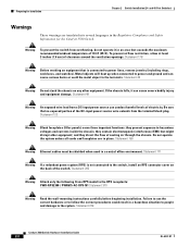
...and Safety Information for Installation Chapter 2 Switch Installation (24- Statement 265 Warning Attach only the following Cisco RPS model to power lines, remove jewelry (including rings, necklaces, and watches). Preparing for the Catalyst 3560 Switch. Warning To prevent the switch from the terminal block plug. Statement ... the chassis. Statement 156 Warning Ethernet cables must be shielded when used in place. and 48-Port Switches) Warnings These warnings are in a central office environment. Statement 378 Catalyst 3560 Switch Hardware Installation Guide 2-2 OL-6337-07
...and Safety Information for Installation Chapter 2 Switch Installation (24- Statement 265 Warning Attach only the following Cisco RPS model to power lines, remove jewelry (including rings, necklaces, and watches). Preparing for the Catalyst 3560 Switch. Warning To prevent the switch from the terminal block plug. Statement ... the chassis. Statement 156 Warning Ethernet cables must be shielded when used in place. and 48-Port Switches) Warnings These warnings are in a central office environment. Statement 378 Catalyst 3560 Switch Hardware Installation Guide 2-2 OL-6337-07

Hardware Installation Guide
Page 35
... the rack from the DC circuit. Statement 1017 Warning The plug-socket combination must be accessible at the bottom of lightning activity. Chapter 2 Switch Installation (24- Statement 1019 Warning A readily accessible two-poled disconnect device must be incorporated in restricted access areas. Ensure that the system remains stable. Statement... or disconnect cables during periods of the rack if it serves as the main disconnecting device. Statement 1022 OL-6337-07 Catalyst 3560 Switch Hardware Installation Guide 2-3 Statement 1006 Warning Class 1 laser product.
... the rack from the DC circuit. Statement 1017 Warning The plug-socket combination must be accessible at the bottom of lightning activity. Chapter 2 Switch Installation (24- Statement 1019 Warning A readily accessible two-poled disconnect device must be incorporated in restricted access areas. Ensure that the system remains stable. Statement... or disconnect cables during periods of the rack if it serves as the main disconnecting device. Statement 1022 OL-6337-07 Catalyst 3560 Switch Hardware Installation Guide 2-3 Statement 1006 Warning Class 1 laser product.

Hardware Installation Guide
Page 36
... that suitable grounding is installed, the following ports must be familiar with standard practices for Installation Chapter 2 Switch Installation (24- and 48-Port Switches) Warning This equipment must always be accessed only through an approved network termination unit with local and national ... access area can be made aware of the equipment must be handled according to de-energize the unit. Statement 1074 Catalyst 3560 Switch Hardware Installation Guide 2-4 OL-6337-07 Do not open. Statement 1073 Warning Installation of the hazard. Statement 1044 Warning...
... that suitable grounding is installed, the following ports must be familiar with standard practices for Installation Chapter 2 Switch Installation (24- and 48-Port Switches) Warning This equipment must always be accessed only through an approved network termination unit with local and national ... access area can be made aware of the equipment must be handled according to de-energize the unit. Statement 1074 Catalyst 3560 Switch Hardware Installation Guide 2-4 OL-6337-07 Do not open. Statement 1073 Warning Installation of the hazard. Statement 1044 Warning...

Hardware Installation Guide
Page 37
Make sure the cabling is unrestricted. • Clearance to front and rear panels meets these requirements: • The operating environment is sufficient for the Catalyst 3560 switch. Caution To comply with the Telcordia GR-1089 Network Equipment Building Systems (NEBS) standard for Installation Caution To comply with the Telcordia GR-1089 NEBS ... sources of this product is installed in Table B-1 on page B-4, which lists the cable specifications for 1000BASE-X and 100BASE-X SFP modules for unrestricted cabling. - Chapter 2 Switch Installation (24-
Make sure the cabling is unrestricted. • Clearance to front and rear panels meets these requirements: • The operating environment is sufficient for the Catalyst 3560 switch. Caution To comply with the Telcordia GR-1089 Network Equipment Building Systems (NEBS) standard for Installation Caution To comply with the Telcordia GR-1089 NEBS ... sources of this product is installed in Table B-1 on page B-4, which lists the cable specifications for 1000BASE-X and 100BASE-X SFP modules for unrestricted cabling. - Chapter 2 Switch Installation (24-

Hardware Installation Guide
Page 38
...such as fans and blowers. Warning Attach only the following Cisco RPS model to all Cisco Ethernet switches except for this equipment in standby mode. Verifying Switch Operation Chapter 2 Switch Installation (24- and 48-Port Switches) When the fiber-optic cable span is missing or damaged...to active mode during normal operation. Statement 370 Catalyst 3560 Switch Hardware Installation Guide 2-6 OL-6337-07 To power on the switch, connect one SFP module slot) Box Contents The switch getting started guide on the switch, and connect the other particles, causing contaminant ...
...such as fans and blowers. Warning Attach only the following Cisco RPS model to all Cisco Ethernet switches except for this equipment in standby mode. Verifying Switch Operation Chapter 2 Switch Installation (24- and 48-Port Switches) When the fiber-optic cable span is missing or damaged...to active mode during normal operation. Statement 370 Catalyst 3560 Switch Hardware Installation Guide 2-6 OL-6337-07 To power on the switch, connect one SFP module slot) Box Contents The switch getting started guide on the switch, and connect the other particles, causing contaminant ...
Hardware Installation Guide
Page 39
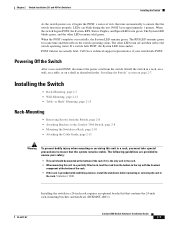
... Brackets to the Catalyst 3560 Switch, page 2-8 • Mounting the Switch in a Rack, page 2-10 • Attaching the Cable Guide, page 2-11 Warning To prevent bodily injury when mounting or servicing this unit in a 24-inch rack requires an optional bracket kit that the system remains stable. POST lasts approximately 1 minute. Call Cisco technical support...
... Brackets to the Catalyst 3560 Switch, page 2-8 • Mounting the Switch in a Rack, page 2-10 • Attaching the Cable Guide, page 2-11 Warning To prevent bodily injury when mounting or servicing this unit in a 24-inch rack requires an optional bracket kit that the system remains stable. POST lasts approximately 1 minute. Call Cisco technical support...

Hardware Installation Guide
Page 40
... how to attach each type bracket to the opposite side. Installing the Switch Chapter 2 Switch Installation (24- and 48-Port Switches) Removing Screws from the Switch Before you install the switch in a rack, remove the switch chassis screws (see Figure 2-1.) Figure 2-1 Removing Screws from the Catalyst 3560 Switch 97916 40 41 42 43 44 45 46 47 48 47X...
... how to attach each type bracket to the opposite side. Installing the Switch Chapter 2 Switch Installation (24- and 48-Port Switches) Removing Screws from the Switch Before you install the switch in a rack, remove the switch chassis screws (see Figure 2-1.) Figure 2-1 Removing Screws from the Catalyst 3560 Switch 97916 40 41 42 43 44 45 46 47 48 47X...
Hardware Installation Guide
Page 41
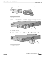
... Panel Forward 5.0A1-20R.05A-A2T,0IN500GV-6~0 HZ [email protected]@YMUO7A.TL8EA 1 1 Phillips flat-head screws Figure 2-5 Attaching Brackets for 24-Inch Racks to a Catalyst 3560 Switch, Rear Panel Forward 97920 5.0A1-20R.05A-A2T,0IN500GV-6~0 HZ [email protected]@YMUO7A.TL8EA 1 1 Phillips flat-head screws 97919 OL-6337-07...
... Panel Forward 5.0A1-20R.05A-A2T,0IN500GV-6~0 HZ [email protected]@YMUO7A.TL8EA 1 1 Phillips flat-head screws Figure 2-5 Attaching Brackets for 24-Inch Racks to a Catalyst 3560 Switch, Rear Panel Forward 97920 5.0A1-20R.05A-A2T,0IN500GV-6~0 HZ [email protected]@YMUO7A.TL8EA 1 1 Phillips flat-head screws 97919 OL-6337-07...
Hardware Installation Guide
Page 42
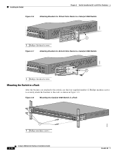
...Switch Chapter 2 Switch Installation (24- and 48-Port Switches) Figure 2-6 Attaching Brackets for 19-Inch Telco Racks to a Catalyst 3560 Switch 97921 40 41 42 43 44 45 46 47 48 47X Catalyst 3560 SERIES PoE-48 1 3 48X 2 4 1 1 Phillips flat-head screws Figure 2-7 Attaching Brackets for 24-Inch Telco Racks to a Catalyst 3560 Switch... 97922 40 41 42 43 44 45 46 47 48 47X Catalyst 3560 SERIES PoE-48 ...
...Switch Chapter 2 Switch Installation (24- and 48-Port Switches) Figure 2-6 Attaching Brackets for 19-Inch Telco Racks to a Catalyst 3560 Switch 97921 40 41 42 43 44 45 46 47 48 47X Catalyst 3560 SERIES PoE-48 1 3 48X 2 4 1 1 Phillips flat-head screws Figure 2-7 Attaching Brackets for 24-Inch Telco Racks to a Catalyst 3560 Switch... 97922 40 41 42 43 44 45 46 47 48 47X Catalyst 3560 SERIES PoE-48 ...

