
Hardware Installation Guide
Page 4
...Devices 2-20 Connecting to Fiber-Optic SFP Modules 2-21 Connecting to 1000BASE-T SFP Modules 2-22 Connecting to a Dual-Purpose Port 2-23 Where to the Switch for Installation 3-1 Warnings 3-2 Installation Guidelines 3-5 Equipment That You Supply 3-6 Catalyst 3560 Switch Hardware Installation Guide iv OL-6337-07 or Shelf- Mounting 2-15 Installing and Removing SFP Modules 2-15 Installing SFP Modules into SFP Module Slots 2-16 Removing SFP Modules from the Switch 2-8 Attaching Brackets to the Catalyst 3560 Switch 2-8 Mounting the Switch in a Rack 2-10 Attaching the Cable Guide 2-11 Wall...
...Devices 2-20 Connecting to Fiber-Optic SFP Modules 2-21 Connecting to 1000BASE-T SFP Modules 2-22 Connecting to a Dual-Purpose Port 2-23 Where to the Switch for Installation 3-1 Warnings 3-2 Installation Guidelines 3-5 Equipment That You Supply 3-6 Catalyst 3560 Switch Hardware Installation Guide iv OL-6337-07 or Shelf- Mounting 2-15 Installing and Removing SFP Modules 2-15 Installing SFP Modules into SFP Module Slots 2-16 Removing SFP Modules from the Switch 2-8 Attaching Brackets to the Catalyst 3560 Switch 2-8 Mounting the Switch in a Rack 2-10 Attaching the Cable Guide 2-11 Wall...

Hardware Installation Guide
Page 11
... started guide provides switch management options, basic rack-mounting procedures, port and module connections, power connection procedures, and troubleshooting help. For power redundancy, all but the Catalyst 3560 8- OL-6337-07 Catalyst 3560 Switch Hardware Installation Guide 1-1 For instructions on how to use Express Setup to initially configure your switch using the command-line interface (CLI), see Appendix D, "Configuring the Switch with the CLI-Based Setup Program." The Catalyst 3560-8PC and the Catalyst 3560-12PC-S compact switches provide the same Power over Ethernet (PoE...
... started guide provides switch management options, basic rack-mounting procedures, port and module connections, power connection procedures, and troubleshooting help. For power redundancy, all but the Catalyst 3560 8- OL-6337-07 Catalyst 3560 Switch Hardware Installation Guide 1-1 For instructions on how to use Express Setup to initially configure your switch using the command-line interface (CLI), see Appendix D, "Configuring the Switch with the CLI-Based Setup Program." The Catalyst 3560-8PC and the Catalyst 3560-12PC-S compact switches provide the same Power over Ethernet (PoE...

Hardware Installation Guide
Page 19
... Appendix B, "Connector and Cable Specifications." • You can use the mdix auto interface configuration command to switches or hubs, use a crossover cable. The auto-MDIX feature is the default. - Never: When you can connect a Cisco IP Phone or Cisco Aironet Access Point to a Catalyst 3560 PoE switch 10/100 or 10/100/1000 port and to the powered device. For information about configuring and monitoring PoE ports, see the switch software configuration guide. For releases between Cisco IOS Release 12.1(14...
... Appendix B, "Connector and Cable Specifications." • You can use the mdix auto interface configuration command to switches or hubs, use a crossover cable. The auto-MDIX feature is the default. - Never: When you can connect a Cisco IP Phone or Cisco Aironet Access Point to a Catalyst 3560 PoE switch 10/100 or 10/100/1000 port and to the powered device. For information about configuring and monitoring PoE ports, see the switch software configuration guide. For releases between Cisco IOS Release 12.1(14...

Hardware Installation Guide
Page 20
... configuring speed and duplex settings for the active connector. 1-10 Catalyst 3560 Switch Hardware Installation Guide OL-6337-07 Use fiber-optic cables with SFP module connectors at a time. Use a Category 5 cable with dual front ends-an RJ-45 connector and an SFP module connector. See "Inserting and Removing the SFP Module Patch Cable" section on page B-4. Each uplink port has two LEDs. Figure 1-11 SFP Module Patch Cable 126809 The SFP module patch cable can use the media-type interface configuration command to other Catalyst series switches, you must use...
... configuring speed and duplex settings for the active connector. 1-10 Catalyst 3560 Switch Hardware Installation Guide OL-6337-07 Use fiber-optic cables with SFP module connectors at a time. Use a Category 5 cable with dual front ends-an RJ-45 connector and an SFP module connector. See "Inserting and Removing the SFP Module Patch Cable" section on page B-4. Each uplink port has two LEDs. Figure 1-11 SFP Module Patch Cable 126809 The SFP module patch cable can use the media-type interface configuration command to other Catalyst series switches, you must use...
Hardware Installation Guide
Page 31
... the Catalyst 3560 Switch Command Reference on Cisco.com for more information. OL-6337-07 Catalyst 3560 Switch Hardware Installation Guide 1-21 The software configuration guide also provides examples of network configurations that use to set of Management Information Base (MIB) extensions and four Remote Monitoring (RMON) groups. The CiscoView application, which you can access the CLI either by using Telnet from the CLI. Network Configurations See the switch software configuration guide on Cisco.com for more information. • SNMP network management You can manage switches...
... the Catalyst 3560 Switch Command Reference on Cisco.com for more information. OL-6337-07 Catalyst 3560 Switch Hardware Installation Guide 1-21 The software configuration guide also provides examples of network configurations that use to set of Management Information Base (MIB) extensions and four Remote Monitoring (RMON) groups. The CiscoView application, which you can access the CLI either by using Telnet from the CLI. Network Configurations See the switch software configuration guide on Cisco.com for more information. • SNMP network management You can manage switches...
Hardware Installation Guide
Page 34
...) serve three important functions: they direct the flow of electricity. Statement 156 Warning Ethernet cables must be shielded when used in a hazardous situation to people and damage to the terminals. Preparing for the Catalyst 3560 Switch. Statement 378 Catalyst 3560 Switch Hardware Installation Guide 2-2 OL-6337-07 Warning To prevent the switch from a DC-input power source can cause serious burns or weld the...
...) serve three important functions: they direct the flow of electricity. Statement 156 Warning Ethernet cables must be shielded when used in a hazardous situation to people and damage to the terminals. Preparing for the Catalyst 3560 Switch. Statement 378 Catalyst 3560 Switch Hardware Installation Guide 2-2 OL-6337-07 Warning To prevent the switch from a DC-input power source can cause serious burns or weld the...

Hardware Installation Guide
Page 36
.... Statement 1074 Catalyst 3560 Switch Hardware Installation Guide 2-4 OL-6337-07 A restricted access area can be grounded. Statement 1044 Warning When installing or replacing the unit, the ground connection must be removed to install, replace, or service this product should be handled according to all national laws and regulations. Statement 1024 Warning This unit might have more than one power supply connection. Avoid using uninsulated exposed metal...
.... Statement 1074 Catalyst 3560 Switch Hardware Installation Guide 2-4 OL-6337-07 A restricted access area can be grounded. Statement 1044 Warning When installing or replacing the unit, the ground connection must be removed to install, replace, or service this product should be handled according to all national laws and regulations. Statement 1024 Warning This unit might have more than one power supply connection. Avoid using uninsulated exposed metal...

Hardware Installation Guide
Page 38
...-Port Switches) When the fiber-optic cable span is missing or damaged, contact your configuration has an RPS, connect the switch and the RPS to an AC power outlet. Network Equipment Building Systems (NEBS) GR-63-CORE - If your Cisco representative or reseller for this equipment in the getting started guide for the steps required to connect a PC to the switch and to all Cisco Ethernet switches...
...-Port Switches) When the fiber-optic cable span is missing or damaged, contact your configuration has an RPS, connect the switch and the RPS to an AC power outlet. Network Equipment Building Systems (NEBS) GR-63-CORE - If your Cisco representative or reseller for this equipment in the getting started guide for the steps required to connect a PC to the switch and to all Cisco Ethernet switches...
Hardware Installation Guide
Page 39
...-Port Switches) Installing the Switch As the switch powers on page 2-7. LEDs can blink during the test. When the POST completes successfully, the System LED remains green. If a switch fails POST, the System LED turns amber. Install the switch in a rack, on a wall, on a table, or on a shelf as described in a rack, you must take special precautions to ensure that the system remains stable. Mounting, page 2-15 Rack-Mounting • Removing Screws from the Switch...
...-Port Switches) Installing the Switch As the switch powers on page 2-7. LEDs can blink during the test. When the POST completes successfully, the System LED remains green. If a switch fails POST, the System LED turns amber. Install the switch in a rack, on a wall, on a table, or on a shelf as described in a rack, you must take special precautions to ensure that the system remains stable. Mounting, page 2-15 Rack-Mounting • Removing Screws from the Switch...
Hardware Installation Guide
Page 47
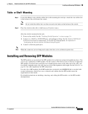
... Switch Hardware Installation Guide 2-15 Installing and Removing SFP Modules The SFP modules are not being used, replace the dust covers on the other end of SFP modules. For detailed instructions on page B-4 for cable stipulations for the switch. See the Catalyst 3560 release notes for instructions. See the Table B-1 on installing, removing, and cabling the SFP module, see Appendix D, "Configuring the Switch with the rubber feet in the rack: 1. Power on the switch. Chapter 2 Switch Installation (24- and 48-Port Switches) Installing and Removing SFP Modules Table...
... Switch Hardware Installation Guide 2-15 Installing and Removing SFP Modules The SFP modules are not being used, replace the dust covers on the other end of SFP modules. For detailed instructions on page B-4 for cable stipulations for the switch. See the Catalyst 3560 release notes for instructions. See the Table B-1 on installing, removing, and cabling the SFP module, see Appendix D, "Configuring the Switch with the rubber feet in the rack: 1. Power on the switch. Chapter 2 Switch Installation (24- and 48-Port Switches) Installing and Removing SFP Modules Table...
Hardware Installation Guide
Page 54
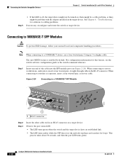
... 30 seconds, and then the port LED turns green. 2-22 Catalyst 3560 Switch Hardware Installation Guide OL-6337-07 Connecting to a 1000BASE-T device, use a four twisted-pair, Category 5 or higher cable. Observe the port status LED. • The LED turns green when the switch and the target device have an established link. • The LED turns amber while the STP discovers the network topology and searches for solutions to a 1000BASE-T SFP Module 97932 40 41 42 43...
... 30 seconds, and then the port LED turns green. 2-22 Catalyst 3560 Switch Hardware Installation Guide OL-6337-07 Connecting to a 1000BASE-T device, use a four twisted-pair, Category 5 or higher cable. Observe the port status LED. • The LED turns green when the switch and the target device have an established link. • The LED turns amber while the STP discovers the network topology and searches for solutions to a 1000BASE-T SFP Module 97932 40 41 42 43...
Hardware Installation Guide
Page 60
...-Port Switches) Warning This equipment must always be familiar with local and national electrical codes. Use the statement number provided at the end of the hazards involved with electrical circuitry and be made first and disconnected last. Statement 1072 Warning No user-serviceable parts inside. Contact the appropriate electrical inspection authority or an electrician if you work on Power over Ethernet (PoE...
...-Port Switches) Warning This equipment must always be familiar with local and national electrical codes. Use the statement number provided at the end of the hazards involved with electrical circuitry and be made first and disconnected last. Statement 1072 Warning No user-serviceable parts inside. Contact the appropriate electrical inspection authority or an electrician if you work on Power over Ethernet (PoE...
Hardware Installation Guide
Page 62
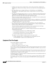
... SFP module slot) Equipment That You Supply You need this equipment to install the switch: • Number-2 Phillips screwdriver • Drill with that might need to provide an RJ-45-to the front of the link. • Cisco Ethernet Switches are available from the switch to connected devices can install an optional cable lock, such as fans and blowers. Catalyst 3560 Switch Hardware Installation Guide 3-6 OL-6337-07 When the fiber...
... SFP module slot) Equipment That You Supply You need this equipment to install the switch: • Number-2 Phillips screwdriver • Drill with that might need to provide an RJ-45-to the front of the link. • Cisco Ethernet Switches are available from the switch to connected devices can install an optional cable lock, such as fans and blowers. Catalyst 3560 Switch Hardware Installation Guide 3-6 OL-6337-07 When the fiber...
Hardware Installation Guide
Page 63
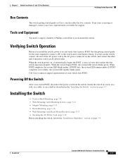
... connect a PC to the switch and to run Express Setup. Powering Off the Switch After a successful POST, disconnect the power cord from the switch. See the getting started guide for support. When POST completes, the system LED blinks amber. If any item is missing or damaged, contact your switch fails POST. OL-6337-07 Catalyst 3560 Switch Hardware Installation Guide 3-7 If POST completes successfully, the system LED rapidly blinks green. Install the switch in a rack...
... connect a PC to the switch and to run Express Setup. Powering Off the Switch After a successful POST, disconnect the power cord from the switch. See the getting started guide for support. When POST completes, the system LED blinks amber. If any item is missing or damaged, contact your switch fails POST. OL-6337-07 Catalyst 3560 Switch Hardware Installation Guide 3-7 If POST completes successfully, the system LED rapidly blinks green. Install the switch in a rack...
Hardware Installation Guide
Page 72
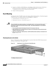
... PoE MODE CONSOLE 1x 2x 3x 4x 5x 6x 7x 8x Catalyst 3560 SERIES PoE-8 1 1 1 Phillips flat-head screws 3-16 Catalyst 3560 Switch Hardware Installation Guide OL-6337-07 To use the CLI setup program, see Appendix D, "Configuring the Switch with the switch (RCKMNT-19-CMPCT=). • Attaching Brackets to the Switch, page 3-16 • Mounting the Switch in a 19-Inch Rack, page 3-17 Warning To prevent bodily injury when mounting or servicing...
... PoE MODE CONSOLE 1x 2x 3x 4x 5x 6x 7x 8x Catalyst 3560 SERIES PoE-8 1 1 1 Phillips flat-head screws 3-16 Catalyst 3560 Switch Hardware Installation Guide OL-6337-07 To use the CLI setup program, see Appendix D, "Configuring the Switch with the switch (RCKMNT-19-CMPCT=). • Attaching Brackets to the Switch, page 3-16 • Mounting the Switch in a 19-Inch Rack, page 3-17 Warning To prevent bodily injury when mounting or servicing...
Hardware Installation Guide
Page 77
... the browser interface, from the command-line interface (CLI), or from an SNMP workstation. See the software configuration guide, the switch command reference guide on Cisco.com or the documentation that came with your SNMP application for more information. • Evaluate Switch POST Results, page 4-2 • Monitor Switch LEDs, page 4-2 • Verify Switch Connections, page 4-2 • Monitor Switch Performance, page 4-4 OL-6337-07 Catalyst 3560 Switch Hardware Installation Guide 4-1 They show failures in the power-on page 1-11. Troubleshooting 4 C H A P T E R The LEDs on...
... the browser interface, from the command-line interface (CLI), or from an SNMP workstation. See the software configuration guide, the switch command reference guide on Cisco.com or the documentation that came with your SNMP application for more information. • Evaluate Switch POST Results, page 4-2 • Monitor Switch LEDs, page 4-2 • Verify Switch Connections, page 4-2 • Monitor Switch Performance, page 4-4 OL-6337-07 Catalyst 3560 Switch Hardware Installation Guide 4-1 They show failures in the power-on page 1-11. Troubleshooting 4 C H A P T E R The LEDs on...
Hardware Installation Guide
Page 80
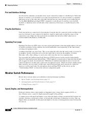
... might be port or interface problems. In this one -way traffic on fiber-optic and twisted-pair links and by its Content-Addressable Memory (CAM) table. In normal mode, UDLD detects unidirectional links because of incorrectly connected interfaces on both sides of the connection. Monitor Switch Performance Review these sections when you find unidirectional link problems. UDLD supports a normal mode of alignment errors, frame check sequence (FCS), or late-collisions errors, a speed or duplex mismatch might...
... might be port or interface problems. In this one -way traffic on fiber-optic and twisted-pair links and by its Content-Addressable Memory (CAM) table. In normal mode, UDLD detects unidirectional links because of incorrectly connected interfaces on both sides of the connection. Monitor Switch Performance Review these sections when you find unidirectional link problems. UDLD supports a normal mode of alignment errors, frame check sequence (FCS), or late-collisions errors, a speed or duplex mismatch might...
Hardware Installation Guide
Page 81
... hold the Mode button. If the switch is not configured, the LEDs above the Mode button turn green. By default, the switch ports and interfaces are set to the latest version available from the manufacturer. The LEDs stop blinking after about 2 seconds. The speed parameter can adjust itself even if the connected port does not autonegotiate. If this does not solve the problem, the firmware or software on your switch to the factory default settings: 1. It is...
... hold the Mode button. If the switch is not configured, the LEDs above the Mode button turn green. By default, the switch ports and interfaces are set to the latest version available from the manufacturer. The LEDs stop blinking after about 2 seconds. The speed parameter can adjust itself even if the connected port does not autonegotiate. If this does not solve the problem, the firmware or software on your switch to the factory default settings: 1. It is...

Hardware Installation Guide
Page 111
... you are connecting the switch to a Cisco redundant power system (RPS), see the documentation that the switch functions properly. Have this information: • Switch IP address • Subnet mask (IP netmask) • Default gateway (router) • Enable secret password • Enable password • Telnet password Step 1 Enter Yes at any point you to enter basic management setup? [yes/no ]: yes At any prompt. When POST completes, the system LED blinks amber. You...
... you are connecting the switch to a Cisco redundant power system (RPS), see the documentation that the switch functions properly. Have this information: • Switch IP address • Subnet mask (IP netmask) • Default gateway (router) • Enable secret password • Enable password • Telnet password Step 1 Enter Yes at any point you to enter basic management setup? [yes/no ]: yes At any prompt. When POST completes, the system LED blinks amber. You...
Hardware Installation Guide
Page 113
... the default configuration that you want to change this configuration to the small form-factor pluggable (SFP) modules, see the CMS online help. If you want to save it the next time the switch reboots, save the configuration and use the CLI, enter commands at the Switch> prompt through the console port by using Telnet. To use CMS, see Chapter 2, "Switch Installation (24- and 48-Port Switches)" and Chapter 3, "Switch Installation (8- If you created. For installation procedures for mounting your switch, connecting...
... the default configuration that you want to change this configuration to the small form-factor pluggable (SFP) modules, see the CMS online help. If you want to save it the next time the switch reboots, save the configuration and use the CLI, enter commands at the Switch> prompt through the console port by using Telnet. To use CMS, see Chapter 2, "Switch Installation (24- and 48-Port Switches)" and Chapter 3, "Switch Installation (8- If you created. For installation procedures for mounting your switch, connecting...


